Received Date:
15 July 2025 Accepted Date:
09 September 2025 Revised Date:
26 August 2025 Available Online:
15 February 2026
Abstract:
Polymer-electrolyte-based solid-state Li metal batteries with high-voltage Ni-rich cathodes are promising energy storage technologies owing to their favorable security and high energy densities. However, operating in wide temperature range and at high voltage is a tough challenge for them. Herein, F/N donating fluorinated-amide-based plasticizers regulated polymer electrolyte capable of enabling high-voltage Li||LiNi0.8Co0.1Mn0.1O2 (NCM811) batteries with excellent performance in wide temperature range is developed. F/N donating fluorinated-amide-based plasticizers significantly improve ionic conductivity (1.52 mS/cm at 30 ℃), enhance oxidation stability (5.0 V vs. Li+/Li) and fabricate robust LiF/Li3N-rich electrode-electrolyte interphases, which significantly improve the interface stability of Li metal anode and NCM811 cathode. The designed polymer electrolyte is nonflammable and has excellent dimensional stability at 200 ℃. Capitalizing on these advantageous attributes, the Li||NCM811 cells show excellent cycle stability and rate capability from −20 ℃ to 60 ℃ at high voltages (~4.6 V), and under high-loading full cell condition, which display impressive capacity retention of 84.4% after 1000 cycles and ultrahigh capacity of 154.8 mAh/g at 10 C. This work provides a rational design strategy of polymer electrolytes for wide-temperature high-energy solid-state Li metal batteries.
Solid-state Li metal batteries (SSLMBs) can theoretically achieve ultrahigh energy densities and favorable security, which have become research hotpots in both academic and industrial world [1]. Among various solid electrolytes, polymer electrolytes (PEs) are suitable electrolytes for SSLMBs owing to their favorable flexibility, good processability, low flammability, low cost, non-leakage and light weight [2]. Li metal anodes are ideal anodes for SSLMBs due to their high specific capacity (3862 mAh/g) and low potential [3,4]. On the cathode side, using prevailing Ni-rich materials (such as LiNi0.8Co0.1Mn0.1O2, NCM811) as cathodes for SSLMBs and increasing the cut-off voltage are feasible strategies to boost the energy densities (> 450 Wh/kg) [5]. For instance, it has been reported that by elevating the charging cut-off voltage from the conventional 4.3 V to 4.7 V can yield an additional ~15%–35% increase in discharge capacity. Therefore, the combination of PEs, Li metal anodes and NCM811 cathodes, and increasing cut-off voltage are ideal strategies to enhance both safety and energy density of SSLMBs.
However, PEs-based SSLMBs suffer from several challenges. Firstly, ionic conductivities of conventional PEs at room temperatures and low temperatures are low (~10−5 S/cm), which cannot support fast charge/discharge of SSLMBs [6-9]. Although the ionic conductivities PEs have been improved by polymer skeleton modification, blending, adding inorganic fillers, plasticizing with small molecules in recent years [10-13], PEs-based SSLMBs still show poor performance at low temperatures (e.g., < 0 ℃), which limits their applications in cold climates [14-16]. Secondly, without special regulation, PEs possess poor interfacial compatibility with NCM811 and Li metal anode [17,18]. The cathode-electrolyte interphase (CEI) and solid electrolyte interphase (SEI) derived from PEs consist of abundant organic and possess poor stability, resulting in low Coulombic efficiency (CE), quick capacity decline and Li dendrites [19,20]. Thirdly, at high temperatures, the mechanical properties of conventional PEs deteriorate, reducing the ability to inhibit Li dendrites and even leading to short circuits, and compromising performance and safety [21-23]. High temperatures also accelerate the interfacial side reactions between PEs and NCM811 cathodes, and exacerbate the deterioration of CEIs and severe phase transitions, leading to poor interfacial stability, fast loss of capacity and low CE. Fourthly, most PEs, e.g., poly(ethylene oxide) (PEO), show low oxidative stability (< 4.0 V vs. Li+/Li), which are readily oxidized on NCM811 at high voltages [24-26]. On the surface of NCM811, oxidative Ni4+ and Co4+ accelerate decompositions of PEO chains at high voltages, resulting in the formation of unstable thick CEI [4]. Extending the charging cut-off voltages over 4.3 V further causes more aggressive oxidative breakdown of PEs [27,28]. So far, few PEs-based SSLMBs have achieve good performance under high voltage and in wide temperature range, which is vital for the practical application of SSLMBs, and has been barely reported and investigated [29-32]. Current researches focus exclusively on the performance of PEs at room temperatures and low voltage, neglecting to investigate their properties at high voltage and in wide temperature range [33-36].
Introducing organic solvents with strong coordinating ability with Li+ into PEs as plasticizers can effectively improve ionic conductivity at low temperature and room temperature [37]. However, the widely used carbonate plasticizers [e.g., ethylene carbonate (EC)] are reactive toward Li, leading to fast consumption of active Li, the construction of fragile SEIs, low CE, short cycle life, and dendritic Li growth [38]. The carbonate-derived SEIs consisting of Li2CO3, ROLi and ROCO2Li possess, which lead to high interfacial impedances, resulting in charge-discharge failure of SSLMBs at low temperatures [39]. The carbonate-derived SEIs also suffer from grievous decomposition at high temperatures. Designing PEs by introducing functionalized plasticizers to improve ionic conductivity, and construct stable and highly conductive SEIs/CEIs seems the most promising strategy to achieve high-performance SSLMBs at high voltage and in temperature range.
In this work, we introduce F/N donating fluorinated-amide-based plasticizers into poly(vinylidene fluoride-co-hexafluoropropylene) (PVDF-HFP) matrix to fabricate nonflammable PE (FFP-PE) capable of constructing stable and highly conductive LiF/Li3N-rich interfaces, which exhibits significantly improved ionic conductivity (1.52 mS/cm at 30 ℃) and enhanced oxidation stability (5.0 V vs. Li+/Li). FFP-PE is nonflammable and has excellent dimensional stability at 200 ℃. Benefiting from these characteristics, the interface stability of Li metal anode and NCM811 was significantly improved by FFP-PE. The Li||NCM811 cells with FFP-PE show excellent cycle stability and rate capability from −20 ℃ to 60 ℃, at high voltage (~4.6 V), and under high-loading full cell condition.
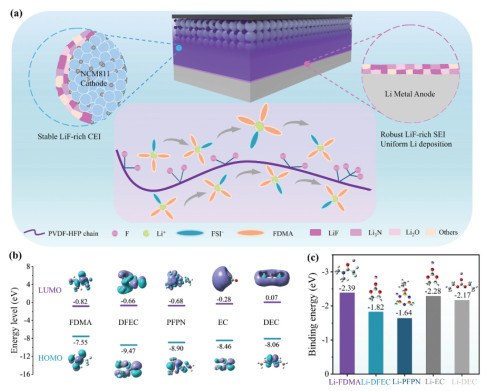
The design and structure of FFP-PE are shown in Fig. 1a. PVDF-HFP with favorable oxidation resistance is employed as the polymer matrix of FFP-PE. N,N-Dimethylformamide (DMF) is widely used to prepare PVDF-HFP-based PEs owing to its high solubility toward PVDF-HFP. However, DMF is highly reactive toward Li metal, which leads to serious corrosion of active Li and poor performance of SSLMBs. Li foils were immersed in DMF for 24 h to investigate its compatibility with Li metal. The Li foil immersed in DMF is severely corroded (Fig. S1 in Supporting information), indicating DMF possesses high reactivity with Li metal. Fluorination of the solvents can enhance compatibility with Li metal. The Li foil immersed in 2, 2, 2-trifluoro-N,N-dimethylacetamide (FDMA) reserves its morphology and gloss (Fig. S1), which indicates favorable compatibility of FDMA with Li metal. Therefore, FDMA is selected as the plasticizer of FFP-PE. Our previous research found that FDMA, in synergy with di-fluoro ethylene carbonate (DFEC) and ethoxy(pentafluoro)cyclotriphosphazene (PFPN), could form stable and highly conductive SEI and CEI both rich in LiF and Li3N, thereby significantly improving the interfacial stability of the lithium metal anode and NCM811 cathode [40]. PFPN can reduce the coordination between FDMA and Li⁺, thereby increasing the proportion of anions in the primary solvation shell (PSS) of Li+ and promoting greater anion participation in the formation of the SEIs/CEIs. Hence, fluorinated-amide based plasticizers consisting of FDMA, DFEC and PFPN were introduced into the PVDF-HFP matrix of FFP-PE to improve the ionic conductivity, and yield LiF and conductive Li3N in the construction processes of SEI/CEI.
Figure 1
Figure 1.
Design principles of FFP-PE. (a) Schematic illustrations of chemical structures, SEI/CEI structures and performance of FFP-PE. (b) LUMO and HOMO energy levels of the solvents. (c) Binding energies between the solvents and Li+.
The lowest unoccupied molecular orbital (LUMO) and highest occupied molecular orbital (HOMO) energy levels of the selected solvents were calculated using density functional theory (DFT) simulations (Fig. 1b), which were used to assess electrochemical behavior. LUMO energy levels of FDMA (−0.82 eV), PFPN (−0.68 eV) and DFEC (−0.66 eV) are significantly lower than that of EC (−0.28 eV) and diethyl carbonate (DEC) (−0.07 eV), which indicates that FDMA/PFPN/DFEC have higher tendency to be reduced in the formation processes of SEI [41]. The reduction of FDMA/PFPN/DFEC is expected to generate abundant LiF and conductive N-containing compounds to boost the stability and Li+ conductivity of SEI. HOMO energy levels of PFPN (−8.90 eV) and DFEC (−9.47 eV) are observably lower than that of EC (−8.46 eV) and DEC (−8.06 eV), indicating DFEC/PFPN possess better oxidative stability. DFEC/PFPN are expected to increase the oxidative stability of PEs under high voltages in SSLMBs. According to the discussion above, FDMA/DFEC/PFPN (6:3:1, v/v/v) was used as the plasticizer of FFP-PE. To investigate the role of the plasticizer and demonstrate the advantage of FFP-PE, control groups including LE-PE consisting of PVDF-HFP and conventional plasticizer (1 mol/L LiPF6 in EC/DEC), and conventional liquid electrolyte (LE) (1 mol/L LiPF6 in EC/DEC) were also included in the study.
The binding energies between Li+ and various solvent molecules are shown in Fig. 1c. FDMA shows the highest binding energy with Li+ (−2.39 eV). It can be assumed prudently that FDMA would dominantly coordinate with Li+ and occupy the primary solvation sheath of Li+ due to strong coordinating ability with Li+, thus shielding DFEC and PFPN away from Li+. The weak ion-dipole interaction between the highly fluorinated plasticizers and fluorinated polymer chain of PVDF-HFP, together with the shielding effect reduce the energy barrier of Li+ conduction, thus enhancing ionic conductivity and facilitating interfacial Li+ transfer kinetic (Fig. 1a).
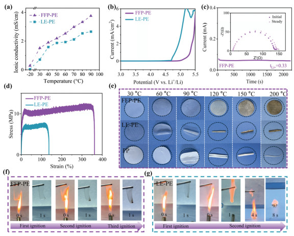
The ionic conductivities of FFP-PE and LE-PE were determined by electrochemical impedance spectroscopy (EIS) at various temperatures. At 30 ℃, FFP-PE displays an ultrahigh ionic conductivity of 1.52 mS/cm (Fig. 2a), which far exceeds that of LE-PE (0.72 mS/cm) and the recently reported polymer electrolytes (Table S1 in Supporting information). Significantly, at an ultralow temperature of −20 ℃, FFP-PE maintains a sufficient ionic conductivity of 0.28 mS/cm, which guarantees efficient Li+ transport for SSLMBs at low temperatures. In sharp contrast, at −20 ℃, LE-PE displays an extremely low conductivity of 0.05 mS/cm, which is insufficient to support the charge-discharge of SSLMBs. At 90 ℃, the ionic conductivity FFP-PE reaches 3.76 mS/cm. The high ionic conductivities of FFP-PE can be ascribed to the strong coordinating ability of FDMA with Li+ and weak ion-dipole interactions between the highly fluorinated plasticizers and fluorinated polymer chains of PVDF-HFP, which accelerate Li+ conduction. The conductivity/temperature curves of FFP-PE and LE-PE were fitted using the Arrhenius equation (Fig. S2 in Supporting information). The corresponding activation energy of FFP-PE is as low as 13.6 kJ/mol, which is significantly lower than that of LE-PE (18.8 kJ/mol), demonstrating lower migration barrier for ion transport.
Figure 2
Figure 2.
Properties of FFP-PE. (a) Ionic conductivities of FFP-PE and LE-PE at various temperatures. (b) LSV of FFP-PE and LE-PE. (c) Chronoamperometry of the Li||Li cell with FFP-PE and the corresponding EIS spectra (the inset) before and after polarization. (d) Stress-strain curves of FFP-PE and LE-PE. (e) Dimensional stability tests of FFP-PE, LE-PE and PP separator at different temperatures. Ignition tests of (f) FFP-PE and (g) LE-PE.
The electrochemical stability windows of FFP-PE and LE-PE were measured using linear sweep voltammetry (LSV) (Fig. 2b). The electrochemical stability window of FFP-PE is 5.0 V, which is significantly higher than that of LE-PE (4.6 V). This result is in accordance with the HOMO analysis. The all-fluorinated plasticizers with low HOMO energy level effectively enhance the oxidation stability of FFP-PE. The Li+ transference numbers (tLi+) of FFP-PE is 0.33 (Fig. 2c), which is higher than that of LE-PE (0.30) (Fig. S3 in Supporting information).
PEs should have good mechanical strength to withstand the stresses of mechanical abuses, charge-discharge cycles, and manufacturing process of SSLMBs. FFP-PE displays a high tensile strength of 12.1 MPa and a high elongation of 362% at break (Fig. 2d), demonstrating favorable mechanical strength and flexibility. In contrast, LE-PE displays a lower tensile strength of 7.2 MPa and a lower elongation of 137% at break.
PEs should retain their shapes and separate anodes and cathodes at high temperature under thermal runaway condition. Dimension stability of FFP-PE, LE-PE and PP separator at high temperature was tested. FFP-PE maintained its original shape from 30 ℃ to 200 ℃ (Fig. 2e), exhibiting outstanding high-temperature dimension stability. In contrast, LE-PE shrank at 60 ℃ and curled up over 120 ℃. PP separator displayed crimp at 90 ℃, and completely melted and shrank into a small particle at 200 ℃, demonstrating poor dimension stability at high temperature.
The flame-resistance of the electrolytes was assessed by ignition tests. FFP-PE cannot be ignited when exposed to the fire even after being ignited three times (Fig. 2f), and the self-extinguishing time (SET) of FFP-PE is 0 s/g (Fig. S4 in Supporting information), demonstrating outstanding flame-retardant property, which is owing to its abundant F and P elements. During pyrolysis process of combustion chain reactions, F and P elements in FFP-PE generate plenty F• and P• free radicals, which can inactivate H• or O• free radicals and terminate the chain reactions of combustion in the gas phase [42-44]. Thus FFP-PE can availably reduce fire risk and improve the safety of SSLMBs [45]. Oppositely, LE-PE combusted fiercely when exposed to the fire (Fig. 2g) and the corresponding SET is 28 s/g (Fig. S4 in Supporting information), which is due to the flammable carbonate plasticizer and a common drawback of conventional PEs. PP separator soaked with conventional LE was also easily ignited and burned violently (Fig. S5 in Supporting information), and displayed a high SET of 36 s/g (Fig. S4 in Supporting information).
Thermogravimetric analysis (TGA) is performed to evaluate the thermal behavior of FFP-PE (Fig. S6 in Supporting information). The minor weight loss before 150 ℃ is attributed to the evaporation of the free DFEC, PFPN and FDMA. And the weight keeps steady between 150 ℃ and 400 ℃, which is owing to that all the residual FDMA molecule coordinate with Li+, and prevent their volatilization. There is a fast loss of 45.5% weight from 400 ℃ and 490 ℃, which corresponds to the evaporation of the coordinated FDMA. The weight keeps steady again over 490 ℃, demonstrating excellent thermal stability of FFP-PE. In contrast, LE-PE displays faster weight loss than FFP-PE from 30 ℃ to 450 ℃.
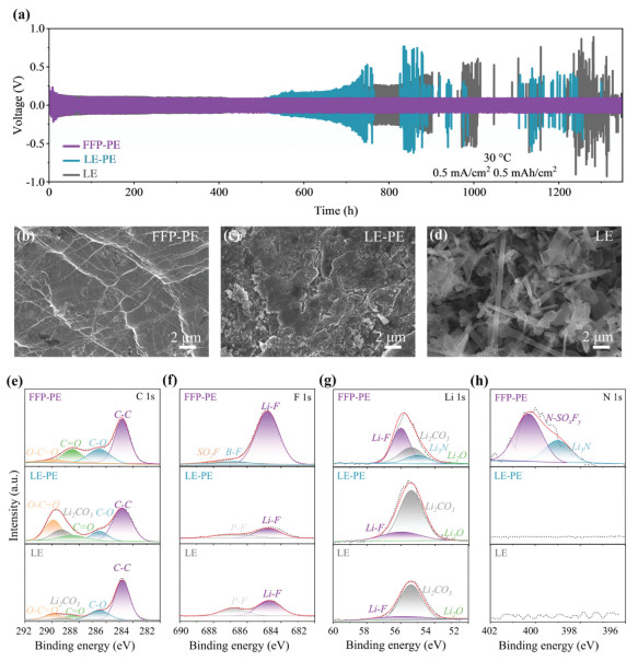
Li plating/stripping cycle of Li||Li cells was used to investigate the compatibility between FFP-PE and Li metal anode. FFP-PE displays a low and steady overpotential (~86 mV) over 1350 h Li plating/stripping cycle (Fig. 3a), indicating favorable interface compatibility with Li metal anode. Oppositely, LE-PE exhibits fast rise of overpotential to 455 mV after 700 h, and plenty rises and drops of overpotential after 740 h, which indicates inferior interface compatibility between LE-PE and Li metal anode, and Li dendrite growth. LE also displays similar poor cycle stability in Li||Li cell due to brittle SEIs and short circuit induced by dendrites. To further quantify the resistance to Li dendrite growth, the critical current density (CCD) of FPP-PE, LE-PE and LE were measured (Fig. S7 in Supporting information). The CCD of FFP-PE is 2.5 mA/cm2, which is obviously higher than that of LE-PE (1.0 mA/cm2) and LE (1.2 mA/cm2), highlighting the superior dendrite suppression capability of FFP-PE.
Figure 3
Figure 3.
Cycle performance of Li||Li cells, morphology of cycled Li and SEI compositions. (a) Voltage-time profiles of Li||Li cells with FFP-PE, LE-PE and LE. SEM images of Li metal anodes after cycled in Li||Li cells with (b) FFP-PE, (c) LE-PE and (d) LE. XPS spectra of Li metal anodes after 50 cycles in Li||Li cells with FFP-PE, LE-PE and LE: (e) C 1s, (f) F 1s, (g) Li 1s and (h) N 1s spectra.
The morphology of Li metal anodes after Li plating/stripping cycle was observed using scanning electron microscopy (SEM). The Li metal anode cycled in FFP-PE shows a dense and smooth surface without any dendrite (Fig. 3b), manifesting that FFP-PE possesses good interfacial compatibility with Li anode, promotes uniform Li+ deposition and restrain dendrite growth. Oppositely, numerous cracks and rough morphology exist at the Li metal anode cycled in LE-PE (Fig. 3c). Plenty pores, particles and Li dendrites are on the surface of the Li metal anode cycled in LE (Fig. 3d), further verifying poor interface compatibility between LE and Li metal anodes.
The compositions of the SEIs of the Li metal anodes after 50 cycles in Li||Li cells with different electrolytes were determined using X-ray photoelectron spectroscopy (XPS). The SEI derived from FFP-PE contains a notably higher F (21.4%) content than that of the SEIs derived from LE-PE (5.7%) and LE (8.9%) (Fig. S8 in Supporting information). The proportion of LiF in the F elements of SEI derived from FFP-PE (87.1%) is obviously higher than that of the SEIs derived from LE-PE (62.1%), and LE (64.6%) (Fig. 3f). Abundant Li3N is also observed in the SEI derived from FFP-PE (Figs. 3g and h). Li3N with high Li+ conductivity (around 10−4 S/cm) is expected to accelerate Li+ conduction at the interfaces and enhance high-rate performance of SSLMBs, especially at low temperatures [46,47]. While the SEIs derived from LE-PE and LE do not contain any Li3N (Figs. 3g and h). The SEI derived from FFP-PE contains other inorganic species, including Li2O, SO2F, B-O and B-F (Fig. 3g, Figs. S9b and c in Supporting information), which are also able to improve the stability. The SEI derived from LE-PE displays high O content (37.2%), abundant O—C═O and low F element content (5.7%) (Fig. 3e, Figs. S8 and S9a in Supporting information), which are derived from the decompositions of carbonate solvents and possess poor electrochemical stability and mechanical property. The SEI derived from LE has abundant organics (Fig. 3e) and low LiF content (Fig. S8), which is fragile and readily broken.
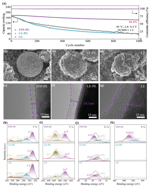
Li||NCM811 cells with FFP-PE were assembled and their cycle performance was tested. When cycled at 30 ℃ and a cut-off voltage of 4.3 V, the Li||NCM811 cell with FFP-PE displays a high initial discharge capacity of 169.9 mAh/g, and shows an impressive capacity retention rate of 84.4% and a high average CE of 99.8% after 1000 cycles (Fig. 4a). In sharp contrast, LE-PE exhibits a low-capacity retention rate of 24.1% and a low average CE of 99.2% after 1000 cycles, due to its poor compatibility with Li metal anode and NCM811. The cell with LE also displays poor cycle performance with a low-capacity retention rate of 22.5% and a low average CE of 98.6% after 1000 cycles. The polarization of the cell with FFP-PE is observably lower than that of the cells with LE-PE and LE over all cycles (Fig. S10 in Supporting information), thanks to the robust SEI/CEI and high ionic conductivity of FFP-PE.
Figure 4
Figure 4.
Cycle performance and structural evolution of Li||NCM811 cells under conventional condition. (a) Cycle performance of Li||NCM811 cells with different electrolytes. SEM of the NCM811 after 1000 cycles in (b) FFP-PE, (c) LE-PE and (d) LE. TEM of NCM811 after 1000 cycles in (e) FFP-PE, (f) LE-PE and (g) LE. XPS spectra of NCM811 after 1000 cycles in different electrolytes: (h) C 1s, (i) F 1s, (j) Li 1s and (k) N 1s spectra.
The structure evolution of the cycled NCM811 was measured using SEM and transmission electron microscopy (TEM). The NCM811 cycled in FFP-PE exhibits smooth intact secondary particles (Fig. 4b), and thin (6.1 nm) uniform CEI (Fig. 4e), indicating FFP-PE facilitates fabricates robust thin CEI, and enhances the interface stability of NCM811. Oppositely, uneven substances exist on the NCM811 cycled in LE-PE (Fig. 4c), which are derived from the decomposition of LE-PE due to its inferior oxidative stability. The CEI derived from LE-PE is thick (10.1 nm) (Fig. 4f). The NCM811 cycled in LE fractures into several parts (Fig. 4d) and shows a thickest (20.4 nm) CEI (Fig. 4g), which is ascribed to the poor oxidation stability of LE and the corrosive HF derived from the decomposition of LiPF6.
The CEI composition of the cycled NCM811 was investigated using XPS. The F content of the CEI derived from FFP-PE (20.9%) is higher than that of the CEIs derived from LE-PE (15.2%) and LE (11.6%) (Fig. S11 in Supporting information). The CEI derived from FFP-PE contains a higher proportion of LiF than that of the SEI derived from LE-PE (Figs. 4i and j), indicating fluorinated plasticizer of FFP-PE facilitates the fabrication of LiF-rich CEI. The CEI derived from FFP-PE also has other substances, including Li3N, B-O and N-SOxFy, which are also able to enhance the stability of CEI (Fig. 4k and Fig. S12 in Supporting information). In all, FFP-PE fabricates robust LiF/Li3N-rich CEIs, boosting long-term interface stability of NCM811. On the contrary, the CEI derived from LE-PE is rich in C═O and C—O with lower LiF content (Figs. 4h and j), which is less stable and readily broken during cycling, resulting in severe interfacial reactions between LE-PE and NCM811. The CEI derived from LE contains abundant organics, which is unstable and readily broken.
The rate performance of Li||NCM811 cells is dramatically boosted by FFP-PE. The cell with FFP-PE delivers high specific capacities of 210.6, 206.6, 199.3, 192.5, 182.9, 176.1, 164.6 and 154.8 mAh/g at 0.1, 0.2, 0.5, 1, 2, 3, 5, 10 C respectively, which are markedly higher than that of the cells with LE-PE and LE (Fig. 5a), which demonstrates outstanding rate capability. Significantly, the cell with FFP-PE shows high specific capacity of 154.8 mAh/g at an ultra-high rate of 10 C, which is attributed to the ultrahigh Li+ conductivity and conductive SEIs/CEIs derived from FFP-PE. Conversely, discharge capacities of the cells with LE-PE and LE at 10 C are 67.6 and 53.4 mAh/g, respectively, indicating their bulk ionic conductivity and SEIs/CEIs are not able to support fast charge/discharge. The cell with FFP-PE displays lower polarizations than the cells with LE-PE and LE at all rates (Fig. S13 in Supporting information). The kinetics of the cells was further studied using galvanostatic intermittent titration technique (GITT) (Fig. S14 in Supporting information). FFP-PE displays an observably lower overpotential (40.3 mV) than LE-PE (50.0 mV) and LE (167.4 mV), verifying the high Li+ transport kinetics of SEIs/CEIs derived from FFP-PE.
Figure 5
Figure 5.
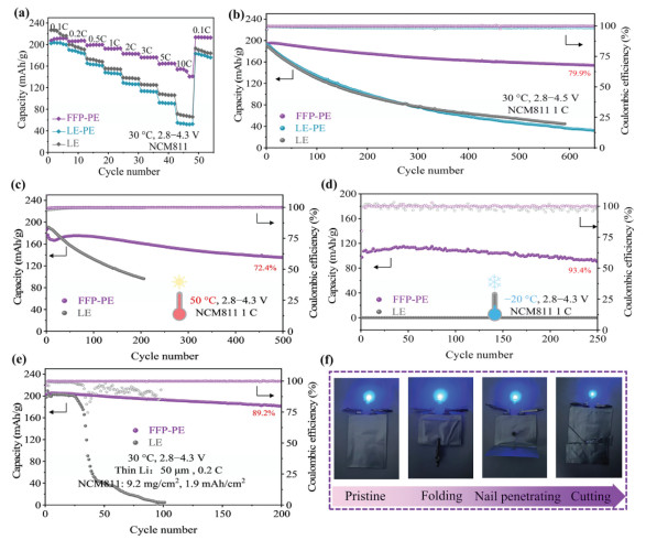
Performance of Li||NCM811 cells under harsh conditions. (a) Rate performance of Li||NCM811 cells with different electrolytes. Cycle performance of Li||NCM811 cells with different electrolytes cycled at (b) a cut-off voltage of 4.5 V, (c) 50 ℃ and (d) −20 ℃. (e) Cycle performance of high-areal-capacity Li||NCM811 full cells. (f) Photographs of the mechanical abuse tests of Li||NCM811 pouch cell with FFP-PE.
Increasing cut-off voltage of NCM811 batteries is a feasible way to increase their energy density. Nevertheless, most conventional PEs cannot support high-voltage charge-discharge of NCM811 SSLMBs due to their low oxidation stability. The cycle performance of Li||NCM811 cells with FFP-PE, LE-PE and LE at an elevated cut-off voltage of 4.5 V was examined. The cell with FFP-PE displays a high initial discharge capacity of 192.5 mAh/g, a high average CE of 99.7%, and a high capacity retention rate of 79.9% after 650 cycles (Fig. 5b), which demonstrates that FFP-PE possesses favorable high-voltage compatibility with NCM811. Oppositely, LE-PE and LE show low capacity retention rates of 16.8% after 650 cycles and 23.7% after 590 cycles at 4.5 V respectively, indicating poor compatibility of LE-PE and LE with NCM811 at high-voltage. After long-term 1000 cycles at a cut-off voltage of 4.4 V, the cell with FFP-PE displays a high capacity retention ratio 73.2% (Fig. S15 in Supporting information), which is distinctly higher than that of the cells with LE-PE (13.4%) and LE (12.6%). When cycled at a higher cut-off voltage of 4.6 V, the cell with FFP-PE also displays a high capacity retention rate of 81.7% after 200 cycles (Fig. S16 in Supporting information), which is higher than that of the cell with LE (53.4%).
Due to the accelerated interfacial reactions and serious surficial reconstruction of NCM811 at elevated temperature, most conventional PEs cannot support high-temperature cycle of NCM811 SSLMBs. Cycle performance of Li||NCM811 cells at 50 ℃ and cut-off voltage of 4.3 V was firstly evaluated. The cell with FFP-PE maintains 72.4% of the initial capacity after 500 cycles (Fig. 5c), indicating superior high-temperature tolerance of FFP-PE and favorable thermal stability of CEI/SEI derived from FFP-PE. Conversely, the capacity of the cell with LE quickly declines to 98.6 mAh/g within 200 cycles, which is ascribed to the decomposition of LiPF6, the generation of corrosive HF, and the destruction of unstable SEI/CEI at high temperatures. When cycled at a higher temperature of 60 ℃, the Li||NCM811 cell with FFP-PE displays a high initial capacity of 204.5 mAh/g, and a high capacity retention rate of 80.0% after 200 cycles (Fig. S17 in Supporting information), which demonstrates excellent high-temperature combability of FFP-PE with Li metal anode and NCM811. LE-PE exhibits a low-capacity retention rate of 47.0% after 200 cycles, due to its inferior thermal stability and generation of HF at elevated temperatures.
Operating at low temperatures is also a formidable challenge for PE-based SSLMBs. At −20 ℃, the Li||NCM811 cell with FFP-PE can still deliver specific capacity up to 118.2 mAh/g and retains 93.4% of the initial capacity after 250 cycles (Fig. 5d), demonstrating excellent low-temperature performance, which is ascribed to the high ionic conductivity of FFP-PE at −20 ℃ and the highly conductive CEIs/SEIs derived from FFP-PE. On the contrary, at −20 ℃, the cell with LE is not able to release any capacity, due to the solidification of LE and the low ionic conductivity of CEI/SEI derived from LE-PE [48].
FFP-PE also drastically enhances the performance of Li||NCM811 full cells with high-loading NCM811 cathodes (9.2 mg/cm2) and thin Li anodes (50 μm) (Fig. 5e). The full cell with FFP-PE exhibits a high capacity of 203.6 mAh/g at the first cycle, a high capacity retention rate of 89.2%, and a high average CE of 99.6% after 200 cycles, thanks to the good compatibility of FFP-PE with Li metal anodes and NCM811 cathodes. On the contrary, the cell with LE exhibits fast capacity descend to 0 mAh/g within 100 cycles, which is caused by fast depletion of active Li due to serious interface reactions.
FFP-PE was used to fabricate Li||NCM811 pouch cells, which were employed to carry out mechanical abuse tests to assess effectiveness of the flexibility and security of FFP-PE in practical SSLMBs (Fig. 5f). The pouch cell is able to effectively power a blue LED lamp, which maintains a steady light after folding, nail penetrating and cutting of the pouch cell, demonstrating outstanding flexibility and safety of the pouch cell. FFP-PE is superior to the recently reported polymer electrolytes in terms of flame retardancy, ionic conductivity, electrochemical stability window, tensile strength and cycle performance of Li||NCM cells (Table S1 in Supporting information), demonstrating the superiority of FFP-PE and F/N synergistic strategy.
In summary, a rational-designed FFP-PE regulated by F/N donating FDMA/DFEC/PFPN plasticizer has been demonstrated to effectively improve the wide-temperature performance of high-voltage Li||NCM811 batteries. FDMA/DFEC/PFPN plasticizer of FFP-PE significantly improves ionic conductivity (1.52 mS/cm at 30 ℃), enhances oxidation stability (5.0 V vs. Li+/Li), and fabricates robust LiF/Li3N-rich SEIs/CEIs with high conductivity, drastically enhancing the interfacial stability of Li metal anodes and NCM811 cathodes. FFP-PE is nonflammable and has excellent dimensional stability at 200 ℃. FFP-PE endows Li||NCM811 cells with excellent cycle stability and rate capability in wide temperature range (−20 ℃ to 60 ℃), at high voltages (~4.6 V) and under high-cathode-loading condition. The Li||NCM811 cells with FFP-PE exhibit an impressive capacity retention of 84.4% after 1000 cycles and ultrahigh specific capacity of 154.8 mAh/g at 10 C rate.
Declaration of competing interest
The authors declare that they have no known competing financial interests or personal relationships that could have appeared to influence the work reported in this paper.
Figure 1
Design principles of FFP-PE. (a) Schematic illustrations of chemical structures, SEI/CEI structures and performance of FFP-PE. (b) LUMO and HOMO energy levels of the solvents. (c) Binding energies between the solvents and Li+.
Figure 2
Properties of FFP-PE. (a) Ionic conductivities of FFP-PE and LE-PE at various temperatures. (b) LSV of FFP-PE and LE-PE. (c) Chronoamperometry of the Li||Li cell with FFP-PE and the corresponding EIS spectra (the inset) before and after polarization. (d) Stress-strain curves of FFP-PE and LE-PE. (e) Dimensional stability tests of FFP-PE, LE-PE and PP separator at different temperatures. Ignition tests of (f) FFP-PE and (g) LE-PE.
Figure 3
Cycle performance of Li||Li cells, morphology of cycled Li and SEI compositions. (a) Voltage-time profiles of Li||Li cells with FFP-PE, LE-PE and LE. SEM images of Li metal anodes after cycled in Li||Li cells with (b) FFP-PE, (c) LE-PE and (d) LE. XPS spectra of Li metal anodes after 50 cycles in Li||Li cells with FFP-PE, LE-PE and LE: (e) C 1s, (f) F 1s, (g) Li 1s and (h) N 1s spectra.
Figure 4
Cycle performance and structural evolution of Li||NCM811 cells under conventional condition. (a) Cycle performance of Li||NCM811 cells with different electrolytes. SEM of the NCM811 after 1000 cycles in (b) FFP-PE, (c) LE-PE and (d) LE. TEM of NCM811 after 1000 cycles in (e) FFP-PE, (f) LE-PE and (g) LE. XPS spectra of NCM811 after 1000 cycles in different electrolytes: (h) C 1s, (i) F 1s, (j) Li 1s and (k) N 1s spectra.
Figure 5
Performance of Li||NCM811 cells under harsh conditions. (a) Rate performance of Li||NCM811 cells with different electrolytes. Cycle performance of Li||NCM811 cells with different electrolytes cycled at (b) a cut-off voltage of 4.5 V, (c) 50 ℃ and (d) −20 ℃. (e) Cycle performance of high-areal-capacity Li||NCM811 full cells. (f) Photographs of the mechanical abuse tests of Li||NCM811 pouch cell with FFP-PE.

 DownLoad:

 下载:
下载:


