Figure 1.
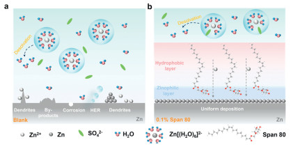
Schematic representations of interfacial dynamics and hydrophobic interfacial layer in (a) blank and (b) 0.1% Span 80 electrolyte.
Hydrophobic protective layer with ultra-long carbon chain for high-performance aqueous zinc ion batteries
Renming Liu , Ze Gao , Linglong Hu , Daming Yang , Ming Feng , Dan Luo

The unsustainable depletion of hydrocarbon resources and progressive deterioration of environmental quality caused by their combustion have driven significant attention toward renewable energy [1,2]. The variable nature of renewables demands efficient energy storage solutions for stable power supply [3,4]. Among various energy storage technologies, lithium-ion batteries (LIBs) have gained widespread adoption because of their high energy density and durable cycle life [5,6]. However, the inherent flammability and explosiveness of organic electrolytes in LIBs raise critical safety concerns [7,8]. Furthermore, the limited global lithium reserves and the resulting high production costs have further restricted their widespread application [9,10]. These challenges have spurred growing interest in aqueous battery systems [11,12].
In aqueous Zn-ion batteries (AZIBs) [13], although water as an electrolyte solvent provides significant benefits such as low cost, high safety, and environmental friendliness, it also introduces several detrimental side effects that severely compromise battery performance and cycling stability [14,15]. A primary concern is the hydrogen evolution reaction (HER) [16], which consumes the electrolyte and generates gaseous hydrogen [17,18], leading to reduced coulombic efficiency and diminished capacity [19]. Furthermore, water reacts with the Zn anode [20], resulting in the corrosion of active Zn materials and the formation of insoluble byproducts (e.g., Zn hydroxide sulfate) [21]. These byproducts accumulate on the electrode surface, increasing interfacial resistance and impairing both rate capability and long-term cycling performance [22]. Moreover, the presence of water exacerbates the inhomogeneous deposition of Zn2+, facilitating the growth of Zn dendrites, which can penetrate the separator and cause internal short circuits [23,24]. Consequently, suppressing the reactivity of water at the Zn anode interface is critical for enhancing the cycle life and overall performance of AZIBs [25,26].
Surfactants form a hydrophobic layer on Zn anodes, limiting water access to suppress reduction reactions, thereby improving coulombic efficiency and safety [27]. The amphiphilic properties of surfactants facilitate a functional interfacial layer on the Zn anode, suppressing HER, dendrite growth, and corrosion while enhancing electrolyte wettability and stability [28,29]. Due to their unique properties, surfactants are widely studied as multifunctional electrolyte additives, such as: Wang et al. showed that sodium dodecyl sulfate (SDS) optimizes Zn2+ deposition, enabling more uniform and stable electrodeposition [30]; Yang et al. found that SDBS enhances interfacial electrostatic adsorption, enabling uniform Zn deposition and suppressing side reactions [31]. Meanwhile, Tang et al. demonstrated that zincophilic APG surfactant restructures electrolyte H-bond networks, lowering free water activity and parasitic reactions [32]. Wang et al. used Tween-80 to guide Zn nucleation, achieving preferential (002)-oriented growth [33]. Furthermore, Liu et al. demonstrated that DTAC stabilizes Zn anodes by disrupting H-bond networks and modifying Zn2+ solvation, enhancing performance [34]. These studies highlight the multifunctional role surfactants in addressing AZIBs challenges. While their carbon chains shield Zn anodes from electrolyte contact, most chains (< 10 carbons) are too short for optimal hydrophobic protection. Thus, investigating longer carbon chains is crucial for enhancing interfacial layer performance.
Herein we introduce a novel nonionic surfactant featuring ultra-long carbon chains with 18 carbons, sorbitan oleate (Span 80) (Fig. S1 in Supporting information) can achieve long-cycle-life AZIBs, which structure is characterized by infrared spectroscopy (Fig. S2 in Supporting information). As shown in Fig. 1a, severe side reactions are observed in the blank electrolyte. In contrast, the hydrophilic sorbitan group of Span 80 anchors onto the Zn anode surface, which effectively regulates Zn2+ deposition uniformity (Fig. 1b). Simultaneously, the ultra-long hydrophobic carbon chains form a robust interfacial layer at the Zn-electrolyte interface, effectively suppressing hydrogen evolution reactions (HER). Owing to these synergistic mechanisms, the adverse side reactions on the Zn anode surface are significantly mitigated. As a result, Span 80 additive confers extraordinary stability, with symmetric cells functioning steadily for over 570 h at a high current density of 50 mA/cm2. Furthermore, in a Zn||V2O5 full cell configuration, the addition of Span 80 markedly enhances cycling performance, delivering 179 mAh/g after 2000 cycles, while also significantly improving rate capability. These findings demonstrate that constructing a hydrophobic interfacial layer with ultra-long carbon chains offers an effective and straightforward strategy for developing high-efficiency Zn-based energy storage devices with enhanced cycling stability.
1H nuclear magnetic resonance (1H NMR) spectroscopy and Fourier transform infrared spectroscopy (FTIR) spectroscopy are employed to investigate the effect of Span 80 on the ZnSO4 electrolyte environment and the solvation structure of Zn2+ [35,36]. As depicted in Fig. 2a, the addition of ZnSO4 results in an upfield shift of the 1H chemical shift of H2O from 4.707 ppm to 4.898 ppm, indicating a reduction in the electron density of H2O molecules due to the strong coordination between Zn2+ and H2O. Upon the introduction of 0.1% Span 80, the 1H chemical shift undergoes a gradual downfield shift to 4.886 ppm, suggesting a weakening of the interaction between Zn2+ and H2O and the subsequent desolvation of coordinated H2O molecules. FTIR analysis (Fig. 2b) demonstrates a significant blue shift in the asymmetric stretching vibration of the sulfate (SO42−) sulfur-oxygen double bond in Span 80 electrolyte. The vibration shifts from 1085 cm−1 to 1095 cm−1 and further to 1109 cm−1, indicating a reduction in the constraints around SO42−. The most probable cause is the diminished electrostatic coupling between Zn2+ and SO42− following the incorporation of the Span 80 additive. These findings collectively demonstrate that the Span 80 additive effectively modulates facilitates the desolvation of Zn2+ and the solvation structure of Zn2+.
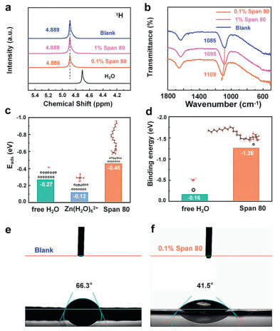
To further elucidate Zn2+ deposition behavior in the 0.1% Span 80 electrolyte, density functional theory (DFT) calculations were performed to comprehensively investigate the adsorption behaviors of both H2O, [Zn(H2O)6]2+, and Span 80 on the Zn anode surface [37]. As evidenced in Fig. 2c, the adsorption energy of Span 80 was calculated to be −0.46 eV, which is significantly lower than the free H2O (−0.27 eV) and [Zn(H2O)6]2+ (−0.12 eV), indicating that Span 80 exhibit a markedly stronger affinity for the Zn anode surface compared to free H2O and [Zn(H2O)6]2+ [38]. The strong adsorption of Span 80 molecules enables them to preferentially occupy active sites on the Zn surface, thereby effectively suppressing the HER and significantly enhancing the corrosion resistance of the Zn anode. Additionally, the interactions between Zn2+ and H2O, Span 80 were also calculated by DFT. The results demonstrated that the binding energy between Span 80 and Zn2+ is −1.26 eV, which lower than the binding energy between Zn2+ and H2O (−0.16 eV), showing a substantially stronger interaction of Span 80 with Zn2+ in the electrolyte (Fig. 2d). DFT results reveal that Span 80 can effectively participate in the solvation shell coordination of Zn2+, effectively suppressing the chances of interaction between H2O and Zn2+. Furthermore, Span 80 also facilitates the desolvation process of H2O and Zn2+, significantly improving the rate performance of Zn anode. To evaluate the effect of Span 80 on the zincophilicity of the electrolyte, contact angles measurements were performed of various solutions on the Zn foil surface [39,40]. As shown in Figs. 2e and f, the addition of Span 80 decreases the contact angle, demonstrating that Span 80 improved the zincophilicity of the electrolyte.
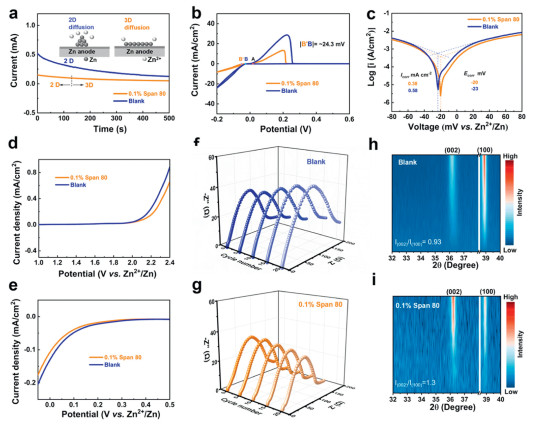
The 2D diffusion of Zn2+ on the anode surface in the electrolyte is the key factor contributing to dendrite formation [41]. The hydrophilic sorbitan group in Span 80 can occupy active sites on the Zn anode surface to regulate the diffusion behavior of Zn2+. Zn2+ diffusion in different electrolytes were investigated by chronoamperometry (CA) measurements with a bias voltage of 20 mV [42]. In the blank electrolyte, the current response of CA curve increases consistently, which indicates the continuous 2D Zn2+ diffusion model. As for 0.1% Span 80 electrolytes, the current response significantly decreases and remains a stable plateau after 120 s, which underscores that the Span 80 can mitigate lateral diffusion of Zn2+ (Fig. 3a). In addition to promoting uniform Zn nucleation and deposition, Span 80 also facilitates the transport kinetics of Zn2+ during the plating/stripping process. Specifically, the activation energy (Ea) for Zn2+ transfer was calculated using the Arrhenius equation. The results demonstrate that the Ea value for the electrolyte with 0.1% Span 80 (18.54 kJ/mol) is significantly lower than that of the blank electrolyte (32.34 kJ/mol) (Fig. S3 in Supporting information). Consequently, the ionic conductivity of the 0.1% Span80 reaches 23 mS/cm according to the Nyquist plots in Fig. S4 (Supporting information), which is much higher than that of blank (19 mS/cm). The tZn2+ were measured to evaluate ionic diffusivity (Fig. S5 in Supporting information). The tZn2+ for the blank and 0.1% Span 80 electrolytes are 0.47 and 0.61, respectively. The higher tZn2+ with Span 80 results from its hydrophobic interphase reducing free water molecules at the Zn surface, thereby suppressing H+ migration. In addition, cyclic voltammetry (CV) curves of different electrolytes were measured in Zn||Cu cells to further explain the nucleation mechanism for the Zn deposition process [43]. Fig. 3b shows that the higher nucleation overpotential in the 0.1% Span 80 electrolyte, which is 24.3 mV higher than that in the blank electrolyte. Thus, Span 80 inhibits parasitic reaction, reduces the Zn nucleation barrier and promotes Zn deposition kinetics, leading to a more uniform and finely deposited layer. The anticorrosion capability of the Zn in different electrolytes were determined by the Tafel tests [44,45]. As shown in Fig. 3c, the corrosion potential (Ecorr) of Zn metal in 0.1% Span 80 (−20 mV) is higher than that in blank electrolyte (−23 mV). The corrosion current density (Icorr) of 0.1% Span 80 is 0.38 mA/cm2, which lower than blank electrolyte (0.58 mA/cm2). These results indicate that Span 80 retards the corrosion reaction of Zn anode. The linear sweep voltammetry (LSV) curve of Zn||Ti cell with 0.1% Span 80 supplies the wider electrochemical window and the lower hydrogen evolution overpotential than blank electrolyte (Figs. 3d and e) [46], which illustrates that hydrophobic protective layer with ultra-long carbon chain surfactants can inhibit water decomposition and hydrogen evolution. To investigate the impact of side reactions on the Zn anode surface, in situ electrochemical impedance spectroscopy (EIS) was performed under cycling conditions by Zn||Zn symmetrical cells [47]. In the blank electrolyte, the EIS decreases and then increases with cumulative deposition time due to the non-uniformity of the Zn deposition. In contrast, the EIS of the 0.1% Span 80 electrolyte rapidly stabilizes during cycling, proving the remarkable Zn anode reversibility and interfacial stability (Figs. 3f and g). The in-situ XRD characterization of the Zn anode was measured at a current density of 5 mA/cm2 [48]. The XRD results (Fig. 3h) indicate that the intensity ratio of (002) to (101) plane increases in 0.1% Span 80 than blank electrolyte (Fig. 3i), which indicated that Span 80 can induce nucleation of Zn along the (002) crystal surface, promote uniform deposition of Zn2+.
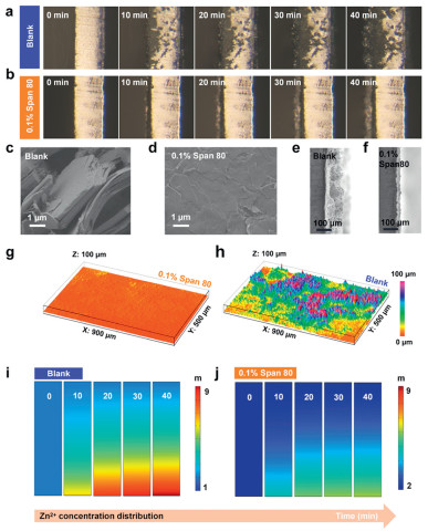
Characterizations of the Zn after plating and stripping to explore hydrophobic protective layer with ultra-long carbon chain surfactants can suppress side reactions and induce Zn electrochemical deposition behavior. The Zn2+ deposition process was visualized by in situ optical microscope [49,50]. During the 40 min electrodeposition process, the surface of Zn anode in the blank electrolyte exhibited the gradual formation of dendritic structures [51], resulting in a significantly rough and uneven morphology (Fig. 4a and Fig. S6 in Supporting information). In contrast, when the electrolyte was supplemented with the Span 80 additive, the Zn anode surface demonstrated highly uniform deposition. As time progresses, the Zn layer thickens progressively, yet no dendritic growth is observed (Fig. 4b) and the Zn anode displays a smooth surfac. These findings suggest that the Span 80 additive plays a critical role in facilitating homogeneous Zn deposition, effectively inhibiting the formation of dendrites. The surface micromorphology of the Zn anode was investigated through scanning electron microscopy (SEM) after 30 cycles in different electrolyte [52,53]. As shown in Fig. 4c and Fig. S7a (Supporting information), the surface of Zn anode was composed of vertically aligned two-dimensional hexagonal sheets and irregular clumps in the blank electrolyte. For the electrolyte with Span 80, the Zn anode shows a tiled morphology without the obvious formation of dendrites (Fig. 4d and Fig. S7b in Supporting information). Notably, the cross-section of the Zn anode cycled in the blank electrolyte exhibited a pronounced dendritic morphology (Fig. 4e). In contrast, the cross-section of the Zn anode cycled in the electrolyte containing the Span 80 additive displayed a dense and uniform deposition layer (Fig. 4f), with no observable dendritic structures. Furthermore, the morphology of Zn anode was also characterized by 3D confocal laser scanning microscopy (CLSM) [54]. Fig. 4g shows that Zn surface after 30 min of electrodeposition of Zn||Zn cell at 5 mA/cm2 with 0.1% Span 80, which can be observed a dendrite-free and smooth surface. However, the exposed Zn anode in the blank electrolyte displays a rugged surface with sharp bumps (Fig. 4h). As a result, the addition of Span 80 significantly suppresses the generation of Zn dendrite and side reactions. Finite element simulations (FEM) were conducted to investigate the deposition process of Zn2+ in different electrolytes, revealing the mechanism of dendrite inhibition [55]. In the blank electrolyte, an imbalance between the reduction rate of Zn2+ and the mass transfer rate led to the accumulation of a large amount of Zn2+ on the surface of the Zn anode at a current density of 5 mA/cm2. This concentration gradient of Zn2+ resulted in dendrite growth (Fig. 4i and Fig. S8a in Supporting information). In contrast, in the presence of 0.1% Span 80, the hydrophilic sorbitol groups and hydrophobic shielding layer guided the uniform deposition of Zn ions, effectively suppressing dendrite formation. As a result, the Zn2+ concentration at the electrode interface achieved a balance with the mass transfer rate, ensuring sufficient Zn2+ for continuous deposition, reducing concentration polarization, and homogenizing the electric field distribution (Fig. 4j and Fig. S8b in Supporting information). The FEM results demonstrated that Span 80 effectively alleviates concentration polarization, homogenizes the electric field, and guides the uniform deposition of Zn2+. Consequently, Span 80 significantly enhances the electrochemical performance. Consequently, Span 80 significantly enhances the electrochemical performance.
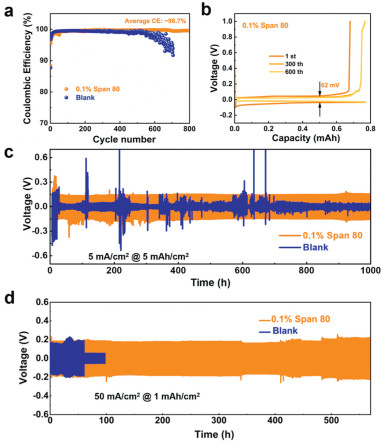
The reversibility and stability of Zn2+ plating-stripping process are considerably augmented by hydrophobic interfacial layer of Span 80. The Coulombic efficiency (CE) of the Zn||Cu cell during reversible plating-stripping tests in the blank electrolyte rapidly deteriorates after 60 cycles, which is primarily attributed to local short circuits induced by dendrite formation. However, the CE with 0.1% Span 80 electrolyte could reach 98.7% and maintain stable operation for > 800 cycles (Fig. 5a). In addition, Fig. 5b and Fig. S9 (Supporting information) shows current charge-discharge (GCD) curves of Zn||Cu cell with 0.1% Span 80 electrolyte and blank electrolyte at the 1st, 300th, 600th cycles, which shows that the 0.1% Span 80 electrolyte shows a small voltage hysteresis of 62 mV, lower than that of blank electrolyte (180 mV) at 600th cycles. This marked decrease in polarization indicates improved reaction kinetics in the presence of the Span 80 additive. Furthermore, Fig. 5c compares the cyclic life of Zn||Zn cells with different electrolyte under a current density of 5 mA/cm2 and 5 mAh/cm2. The cyclic life with blank electrolyte only maintains < 100 h, and the cycle performance after adding 0.1% Span 80 can sustain 2000 h. Furthermore, Zn||Zn cell delivers a cycling life of over 570 h at 50 mA/cm2 before short-circuit in 0.1% Span 80. However, the Zn||Zn symmetric battery lasted only 60 h (Fig. 5d). The overlong cycle life and high CE can be ascribed to the effectively suppressed dendrite growth and the vastly improved migration ability of Zn2+. To investigate the impact of Span 80 additive under elevated current densities, the current density increases from 1 mA/cm2 to 50 mA/cm2 with a constant areal capacity of 1 mAh/cm2 (Fig. S10 in Supporting information). Zn||Zn cell with 0.1% Span 80 exhibits a stable voltage profile, and which reduced polarization compared to the blank. Thereby demonstrating decent stability of the Span 80 electrolyte. Table S1 (Supporting information) shows the cycling performance of Zn||Zn symmetric cells with electrolyte additives featuring different carbon chain lengths under high-current conditions. The results demonstrate that hydrophobic interfacial layers with ultra-long carbon chains exhibit superior electrochemical stability.
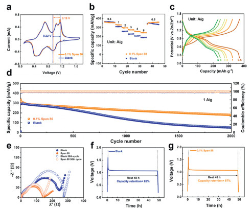
After demonstrating exceptional electrochemical stability in the Span 80 electrolyte with the half-cell, in order to explore the influence of Span 80 on the cycle the performance of full cells, V2O5 was chosen as the cathode [56,57]. The CV curves of Zn||V2O5 were scanned from 0.2 V to 1.7 V with different electrolyte (Fig. 6a). In the CV curves, the voltage gap between the redox peaks in the 0.1% Span 80 electrolyte is narrower compared to the control group, indicating reduced polarization in the Zn||V2O5 full cell, thereby enhancing its rate capability under high-current conditions. As shown in Fig. 6b, the specific discharge capacity of the full cell with and without Span 80 of the electrolyte was about 365 mAh/g at current density of 0.5 A/g. As current density increased, both battery types exhibited reduced discharge specific capacity. When the current density increases to 5 A/g, the specific discharge capacity of the blank electrolyte decreases to 189.9 mAh/g, which was only 52% of the initial capacity. However, the electrolyte with Span 80 can deliver a high discharge capacity of 243.3 mAh/g, which substantially exceeded the blank electrolyte, indicating its high capacity retention rate under high current density. The GCD profiles corresponding to rate performance with Span 80 electrolyte are displayed in Fig. 6c. The curves exhibit remarkable symmetry, indicating high reversibility and excellent discharge-charge capabilities. As shown in Fig. 6d, the Zn||V2O5 cell capacity of blank electrolyte at 1 A/g is about 300 mAh/g. After 500 cycles, the discharge specific capacity decreases significantly, and the cell almost failed at 2000 cycles. However, the discharge capacity decreases slightly after 2000 cycles with 0.1% Span 80 electrolyte additive, and the capacity retention rate exceeds 86%. Moreover, as shown in Fig. 6e, with the addition of Span 80, the Rct of the electrolyte is lower than blank electrolyte in full cell, and after 50 cycles, the blank electrolyte exhibited a significant increase in resistance, while the 0.1% Span 80 maintained stable interfacial impedance with negligible change. To sum up, Span 80 additive can successfully improve the cycle stability of the Zn||V2O5 full cell. Meanwhile, the inhibition effect of Span 80 on the parasitic reaction was investigated through the self-discharge of Zn||V2O5 full cell [58]. As shown in Figs. 6f and g, the capacity retention rate of Zn||V2O5 cells prepared with 0.1% Span 80 electrolyte is 87% after 48 h of shelving, which is much higher than that of the blank electrolyte (82%). In addition, SEM analysis of cycled Zn anodes revealed that the 0.1% Span 80-containing Zn||V2O5 full cells maintained smooth electrode surfaces after 50 cycles, while the blank electrolyte exhibited severe pitting and protrusions (Fig. S11 in Supporting information), demonstrating that Span 80 can promote uniform Zn2+ deposition.
In conclusion, a hydrophobic shielding layer is engineered in aqueous ZnSO4 electrolyte by introducing the nonionic surfactant Span 80, leveraging its ultra-long carbon chains. Through combined DFT calculations and in situ characterization, we reveal that this hydrophobic layer not only facilitates the desolvation of [Zn(H2O)6]2+ solvation structures but also mitigates parasitic side reactions and hydrogen evolution. Additionally, the hydrophilic sorbitol moieties in Span 80 preferentially adsorb onto Zn anode active sites, guiding uniform Zn2+ deposition and suppressing dendritic growth. Consequently, the Zn||Zn symmetric cell delivers an extended cycling lifespan of 570 h at 50 mA/cm2, while the Zn||V2O5 full cell retains exceptional stability over 2000 cycles. These findings underscore the promising role of long-chain surfactants as functional electrolyte additives for high-performance AZIBs.
The authors declare that they have no known competing financial interests or personal relationships that could have appeared to influence the work reported in this paper.
Renming Liu: Writing – review & editing, Writing – original draft, Investigation, Formal analysis, Data curation, Conceptualization. Ze Gao: Writing – original draft, Conceptualization. Linglong Hu: Writing – review & editing. Daming Yang: Writing – review & editing. Ming Feng: Writing – review & editing, Investigation, Formal analysis, Data curation, Conceptualization. Dan Luo: Writing – review & editing, Supervision, Funding acquisition, Data curation, Conceptualization.
This work was supported by the financial support from the Guangdong Basic and Applied Basic Research Foundation (No. 2023B1515120095), the National Natural Science Foundation of China (Nos. 52471229 and 52171210) and the Jilin Province Science and Technology Department Program (No. 20240101004JJ).
Supplementary material associated with this article can be found, in the online version, at doi:10.1016/j.cclet.2025.111491.
J. Yue, S. Chen, J. Yang, et al., Adv. Mater. 36 (2024) 2304040. doi: 10.1002/adma.202304040
S. Sahoo, R. Kumar, I. Hussain, et al., Adv. Powder Mater. 3 (2024) 100246. doi: 10.1016/j.apmate.2024.100246
X. Shi, Y. Zhong, Y. Yang, et al., Angew. Chem. Int. Ed. 137 (2025) e202414777. doi: 10.1002/ange.202414777
X. Zhang, Y. Ding, Battery Energy 4 (2025) 20240046. doi: 10.1002/bte2.20240046
T.Z. Yang, Y. Zheng, Y.Z. Liu, et al., Renewables 1 (2023) 2–20. doi: 10.31635/renewables.022.202200007
G.H. Zhao, W.W. Liu, B. Zhang, et al., Renewables 3 (2025) 21–30. doi: 10.31635/renewables.025.202400075
J. Shin, J.W. Choi, Adv. Energy Mater. 10 (2020) 2001386. doi: 10.1002/aenm.202001386
L. Huang, J. Zhu, J.X. Liu, et al., J. Adv. Ceram. 13 (2024) 1093–1118. doi: 10.26599/jac.2024.9220913
Z. Wang, Z. Ni, J. Chen, et al., Energy Storage Mater. 75 (2025) 104064. doi: 10.1016/j.ensm.2025.104064
S.C. Miao, Y. Jia, Z.W. Deng, et al., Tungsten 6 (2024) 212–229. doi: 10.1007/s42864-023-00231-3
H. Yu, Z. He, D. Chen, et al., Energy Rev. 4 (2025) 100107. doi: 10.1016/j.enrev.2024.100107
D.J. Xiao, X.M. Lv, J.H. Fan, et al., Energy Mater. 3 (2023) 300007.
Y. Song, P. Ruan, C. Mao, et al., Nano Micro Lett. 14 (2022) 218. doi: 10.1007/s40820-022-00960-z
S. Li, Y. Zhong, J. Huang, et al. Energy Environ. Sci. 18 (2025) 2599–2609. doi: 10.1039/d4ee04372c
J.H. Lin, Y.T. Yan, J.L. Qi, et al., Tungsten 6 (2024) 269–277. doi: 10.1007/s42864-023-00232-2
X. Wu, Y. Dai, N.W. Li, et al., eScience 4 (2024) 100173. doi: 10.1016/j.esci.2023.100173
J. Chen, J. Xiong, M. Ye, et al., Adv. Funct. Mater. 34 (2024) 2312564. doi: 10.1002/adfm.202312564
J. Cao, X. Wang, S. Qian, et al., Adv. Mater. 36 (2024) 2410947. doi: 10.1002/adma.202410947
S. Chen, K. Ouyang, Y. Liu, et al., Adv. Mater. 37 (2025) 2417775. doi: 10.1002/adma.202417775
S. Cai, J. Hu, Y. Luo, et al., Energy Storage Mater. 74 (2025) 103944. doi: 10.1016/j.ensm.2024.103944
H. Liu, X. Hou, Q. Zhang, et al., Adv. Energy Mater. 15 (2025) 2406171. doi: 10.1002/aenm.202406171
J. Li, Y. Long, X. Yu, et al., Energy Storage Mater. 76 (2025) 104154. doi: 10.1016/j.ensm.2025.104154
Y. Chen, Z. Zhang, P. Cai, et al., Angew. Chem. Int. Ed. 137 (2025) e202420284. doi: 10.1002/ange.202420284
J. Cao, H. Wu, Y. Yue, et al., J. Energy Chem. 99 (2024) 671–680. doi: 10.1016/j.jechem.2024.08.023
J. Li, H. Zhang, Z. Liu, H. et al., Adv. Funct. Mater. 35 (2024) 2412865.
C. Ma, L. Tang, H. Cheng, et al., Battery Energy 3 (2024) 20230058. doi: 10.1002/bte2.20230058
L. Zhang, M. Lin, Z. Yu, et al., Energy Storage Mater. 75 (2025) 104022. doi: 10.1016/j.ensm.2025.104022
Y.B. Qiu, Y.S. Lin, D.H. Shi, et al., Adv. Mater. 37 (2025) 2415373. doi: 10.1002/adma.202415373
N. Guo, Z. Peng, W. Huo, et al., Small 19 (2023) 2303963. doi: 10.1002/smll.202303963
N. Chen, Y. Huang, Y. Lv, et al., Molecules 30 (2025) 529. doi: 10.3390/molecules30030529
W. Xie, K. Zhu, W. Jiang, et al., ACS Nano 18 (2024) 21184–21197. doi: 10.1021/acsnano.4c04181
H.C. Wang, M.Y. Zhu, H.B. Wang, et al., Energy Storage Mater. 67 (2024) 103238. doi: 10.1016/j.ensm.2024.103238
Z.L. Zhang, S.X. Yan, H.Y. Dong, et al., J. Colloid Interface Sci. 677 (2025) 885–894. doi: 10.1016/j.jcis.2024.08.022
X.L. Zhang, L. Chen, R. Orenstein, et al., Energy Storage Mater. 70 (2024) 103500. doi: 10.1016/j.ensm.2024.103500
D. Feng, Y. Jiao, P. Wu, Angew. Chem. Int. Ed. 135 (2023) e202314456. doi: 10.1002/ange.202314456
T. Wang, P. Wang, L. Pan, et al., Adv. Energy Mater. 13 (2023) 2203523. doi: 10.1002/aenm.202203523
T. Li, A. Naveed, J. Zheng, et al., Angew. Chem. Int. Ed. 64 (2025) e202424095. doi: 10.1002/anie.202424095
Y. Li, L. Liu, H. Zhang, et al., Adv. Funct. Mater. 35 (2025) 2410855. doi: 10.1002/adfm.202410855
L. Lin, Z. Shao, S. Liu, et al., Angew. Chem. Int. Ed. 64 (2025) e202425008. doi: 10.1002/anie.202425008
Y. Duan, B. Li, K. Yang, et al., Nano Micro Lett. 17 (2025) 79. doi: 10.1007/s40820-024-01586-z
Q. Li, G. Liu, S. Zhou, et al., Chem. Eng. J. 506 (2025) 159895. doi: 10.1016/j.cej.2025.159895
H. Ma, H. Chen, M. Chen, et al., Nat. Commun. 16 (2025) 1014. doi: 10.1038/s41467-025-56325-8
D. Wang, D. Zhao, L. Chang, et al., Energy Storage Mater. 74 (2025) 103903. doi: 10.1016/j.ensm.2024.103903
L. Hong, J. Guan, Y. Tan, et al., Energy Environ. Sci. 17 (2024) 3157–3167. doi: 10.1039/d4ee00199k
B.R. Xu, Q.A. Li, Y. Liu, et al., Rare Met. 43 (2024) 1599–1609. doi: 10.1007/s12598-023-02541-4
G. Li, K. Sheng, Y. Lei, et al., Energy Mater. 3 (2023) 300021.
M. Zhu, R. Gao, Q. Ran, et al., Angew. Chem. Int. Ed. 64 (2025) e202425080. doi: 10.1002/anie.202425080
L. Han, Z. Yuan, X. Shao, et al., Chin. Chem. Lett. 34 (2023) 107868. doi: 10.1016/j.cclet.2022.107868
M. Tang, X. Zhao, R. Han, et al., Angew. Chem. Int. Ed. 64 (2025) e202421574. doi: 10.1002/anie.202421574
Z. Yin, L. Xie, W. Yin, et al., Chin. Chem. Lett. 35 (2024) 108628. doi: 10.1016/j.cclet.2023.108628
X.X. Zhang, Y.Q. Chen, C.X. Lin, et al., Rare Met. 43 (2024) 3735–3747. doi: 10.1007/s12598-023-02561-0
X. Ma, Q. Wang, X. Zhang, et al., Energy Environ. Sci. 18 (2025) 982–990. doi: 10.1039/d4ee04870a
Z. Gao, R. Liu, D. Yang, et al., J. Alloys Compd. 1010 (2025) 177106. doi: 10.1016/j.jallcom.2024.177106
Y. Huang, H. Yan, W. Liu, et al., Angew. Chem. Int. Ed. 63 (2024) e202409642. doi: 10.1002/anie.202409642
L. He, C. Lin, L. Zeng, et al., Angew. Chem. Int. Ed. 64 (2025) e202415221. doi: 10.1002/anie.202415221
B. Ye, F. Wu, R. Zhao, et al., Adv. Mater. 37 (2025) 2501538. doi: 10.1002/adma.202501538
D. Zhang, J. Cao, C. Yang, et al., Adv. Energy Mater. 15 (2025) 2404026. doi: 10.1002/aenm.202404026
C. Zhang, Y. Huang, X. Xu, et al., Energy Environ. Sci. 17 (2024) 4090–4103. doi: 10.1039/d4ee00535j

Figure 1 Schematic representations of interfacial dynamics and hydrophobic interfacial layer in (a) blank and (b) 0.1% Span 80 electrolyte.

Figure 2 Theoretical study on Span 80. (a) 1H NMR and (b) FTIR of electrolyte with different Span 80 concentrations. (c) Adsorption energy of free H2O, [Zn(H2O)6]2+ and Span 80 molecules on Zn surface. (d) Binding energy of Zn with Span 80 and H2O. (e, f) Contact angle of blank and 0.1% Span 80 electrolyte additive on Zn foil surface.

Figure 3 Electrochemical performance of different batteries. (a) CA curves of Zn anode in different electrolyte at 20 mV. (b) CV curves of Zn||Cu cells. (c) Tafel curves of Zn||Zn cells. (d, e) LSV curves. (f, g) In-situ EIS spectra of the Zn||Zn symmetrical cells with/without Span 80 additive. (h, i) In-situ XRD patterns of Zn anode using different electrolyte.

Figure 4 Zn deposition morphologies in different electrolytes. (a, b) In situ optical microscopy images of Zn anodes deposited for 30 min using blank electrolyte and 0.1% Span 80 electrolyte at 5 mA/cm2. SEM of Zn anode on the top view and side view of blank electrolyte (c, e) and 0.1% Span 80 additive (d, f) after 30 cycles at 1 mA/cm2 and 1 mAh/cm2. 3D CLSM images of Zn anodes with (g) 0.1% Span 80 additive and (h) blank additive after 30 cycles at 1 mA/cm2 and 1 mAh/cm2. (i, j) The finite element simulation (FEM) in different electrolytes of Zn2+ concentration distribution.

Figure 5 Electrochemical performance of the half cells. (a) Coulombic efficiency of Zn||Cu asymmetric cells in different electrolytes at 0.5 mA/cm2 and 0.5 mAh/cm2. (b) Voltage profiles of Zn plating/stripping in 0.1% Span 80. Long-term cycling performance of Zn||Zn symmetric cells in electrolyte with/without Span 80 (c) 5 mA/cm2, 5 mAh/cm2 and (d) 50 mA/cm2, 1 mAh/cm2.

Figure 6 Electrochemical performance of the Zn||V2O5 full cell. (a) CV curves in electrolyte with/without Span 80. (b) Rate performances and (c) charge/discharge curves. (d) Long cycle performance at 1 A/g. (e) EIS spectra in different electrolytes. Self-discharge curves of Zn||V2O5 cells in (f) blank electrolyte and (g) 0.1% Span 80 electrolyte.

 扫一扫看文章

扫一扫关注我们
 DownLoad:
 下载:
下载: