Figure 1.
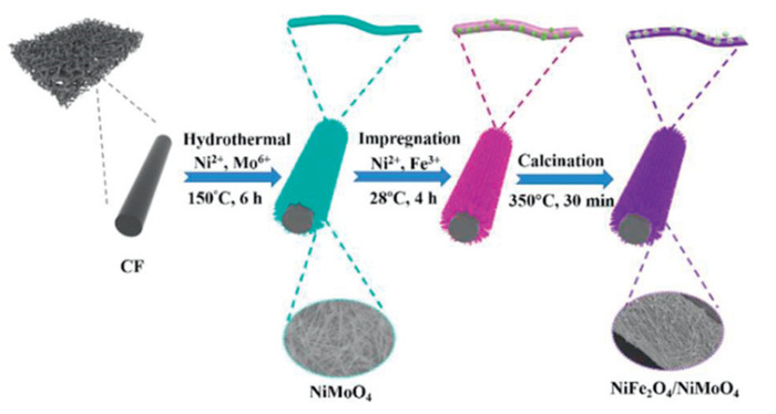
Schematic illustration of the synthesis of 1D self-supporting NiFe2O4/NiMoO4 heterostructure on CF.
1D self-supporting NiFe2O4/NiMoO4 heterostructure as bifunctional electrocatalyst via interface engineering for highly efficient seawater splitting
Lili Wang , Xujie Han , Baichuan Xiong , Ya Yan , Cheng Zhang , Yuning Qu , Yiran Zhang , Linlin Zheng , Zirui Gao , Shuheng Tian , Wenjing Dai , Bowen Cheng , Hang Zhang , Zhen Yin

To address the energy crisis and environmental problems, there is an urgent need to explore environmentally friendly and sustainable energy conversion technologies, among which, hydrogen is a renewable and clean energy source, which occupies an important position in the future, and its preparation, storage, transportation and application have attracted extensive attention [1–3]. Consequently, advancing green hydrogen technologies represents a crucial pathway toward sustainable energy solutions [4]. Green hydrogen can be produced by water electrolysis utilizing renewable electricity (e.g., photovoltaic or wind power) [5–7]. However, the slow kinetics of oxygen evolution reaction (OER) and hydrogen evolution reaction (HER) result in high overpotentials and excessive energy consumption during the water splitting process [8,9], which hinders industrial hydrogen production through water splitting. Ir/Ru-based and Pt-based electrocatalysts are widely used as OER and HER electrocatalysts, respectively [10]. However, high prices and scarcity limit their large-scale application [11]. Thus, it is urgent to explore low-cost and efficient electrocatalysts to replace precious metal catalysts [12,13].
Actually, fresh water reserves are relatively limited, accounting for only 2.53% of the world's total water while seawater accounts for 96.5% of global water reserves [14–16], which can well support the long-term operation of electrochemical water splitting. Unfortunately, the complex seawater compositions pose great challenges for efficient and sustainable water electrolysis [16]. For seawater splitting, chlorine evolution reaction (CER) competes with the OER reaction on the anode, and ClO- as an oxidation product of CER under alkaline conditions, can cause serious corrosion problems throughout the electrolyzer [17,18]. Moreover, the active sites are easily blocked during the electrolysis process due to the various ions (e.g., Mg2+, Ca2+) and microbes in seawater, which makes the electrolysis process extremely unstable [17–20]. Hence, it is important to develop efficient and stable electrocatalysts for seawater splitting at industrial level. So far, transition metal-based electrocatalysts, such as transition metals-based oxides, nitrides, sulfides, and phosphates, have been applied to seawater splitting due to its low-cost, high performance and stability in alkaline media [21]. Especially, NiFe oxides are considered to be one of the most ideal OER electrocatalysts due to their low cost and environmental friendliness, but they usually exhibit obvious instability under OER conditions and cannot meet the requirements of commercial alkaline electrolyzers for electrocatalysts [22,23]. Meanwhile, most of the reported NiFe-based oxides electrocatalysts show only acceptable HER activity. Therefore, in order to achieve large-scale industrial seawater splitting, it is necessary to further improve the electrocatalytic performance of NiFe oxides.
Recently, the construction of heterostructures has been considered an effective strategy to improve the catalytic activity of bifunctional electrocatalysts [24]. This is due to the interaction of electrons between different interfaces, which allow the distribution of electrons to be adjusted to improve the intrinsic activity of the electrocatalyst [25,26]. Furthermore, synergistic components can also exhibit better electrocatalytic performance than one-component catalysts [27]. For example, Ni/NiFe LDH electrocatalyst requires low overpotentials of 150 and 234 mV at a current density of 300 mA/cm2 for HER and OER in 1 mol/L KOH solution, respectively [26,28]. Although the synergistic effect of Ni and NiFe LDH interface accelerates the charge transfer process for promoting reaction kinetics of OER, it only lasts for 24 h to drive 100 mA/cm2 [26,29]. In addition, by combining Mo with transition metal oxides, the adsorption energy of the reaction intermediates can be adjusted to increase the reactive sites, thereby improving the stability of the electrocatalysts [29–31]. Meanwhile, the doping of Mo can optimize the Gibbs free energy (ΔG*H) of hydrogen and increase the mass transfer process, which is beneficial for enhancing performance of the electrocatalytic HER for seawater splitting [32,33]. Therefore, it is necessary to construct hetero-structural electrocatalysts with abundant heterogeneous interfaces to enhance the intrinsic catalytic activity and stability at the industrial level.
In this work, a self-supporting NiFe2O4/NiMoO4 heterostructure electrocatalyst was prepared on carbon felt for overall seawater splitting in alkaline media. Benefit by the rich heterogeneous interfaces formed by the heterostructure decorated by NiFe2O4 nanoparticles on 1D NiMoO4 nanowires and the strong binding effect between the active components and the carbon felt substrate, the electrocatalyst exposes more active sites, increases its electrochemically active surface area and accelerates the transfer of electrons, thereby promoting the reaction kinetics and improving the intrinsic activity of the electrocatalyst. Such electrocatalyst achieves low overpotentials of 237 and 292 mV for OER and HER at the current density of 400 mA/cm2 in simulated alkaline seawater (1 mol/L KOH + 0.5 mol/L NaCl) accompanied by the Faradaic efficiency of 99%. Furthermore, the electrocatalyst exhibits low splitting voltages of 1.95 and 1.99 V at the current density of 400 mA/cm2 in simulated alkaline seawater and actual seawater (1 mol/L KOH + seawater), respectively, and excellent stability for 100 h at the current density of 100 mA/cm2.
The preparation of the NiFe2O4/NiMoO4 heterostructure is shown in Fig. 1. CF is used as a substrate for catalytically active components due to its good electrical conductivity, large surface area, good mechanical properties with low cost (Fig. S1 in Supporting information) [34]. Next, NiMoO4 nanowires were synthesized on CF by hydrothermal method. Subsequently, it is soaked in a mixed solution containing Ni2+ and Fe3+. Finally, a 1D self-supporting NiFe2O4/NiMoO4 electrocatalyst with heterostructure was formed by calcination in N2 atmosphere.
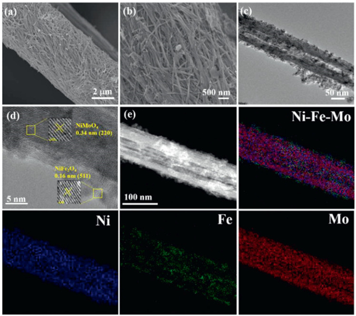
The SEM images in Fig. S2 (Supporting information) show that NiMoO4 nanowires are uniformly and densely wrapped around CF and can act as precursors for subsequent nanoparticle growth. After calcination in N2, the nanowires become coarser than before, and the nanoparticles are also attached to the nanowires (Figs. 2a and b). The TEM imaging can clearly confirm the formation of heterostructures and the diameter of NiMoO4 nanowires is about 40 nm (Fig. 2c). The dense growth of NiMoO4 nanowires can provide abundant active sites and form a three-dimensional structure for gas transport and electrolyte diffusion [29]. As a comparison, since the NiFe2O4 nanoparticles are directly synthesized on CF and there are no NiMoO4 nanowires, the formed NiFe2O4 nanoparticles are prone to accumulation and agglomeration on CF without the support of NiMoO4 nanowires (Fig. S3 in Supporting information). The HRTEM imaging in Fig. 2d exhibits the lattice spacings of 0.34 nm corresponds to the (220) crystal plane of NiMoO4 [35], and the lattice spacing of 0.16 nm is attributed to the (511) crystal plane of the NiFe2O4 phase [36], which indicates the formation of NiFe2O4/NiMoO4 heterostructure. In selected area electron diffraction (SAED, Fig. S4 in Supporting information), the NiFe2O4/NiMoO4 displays four distinct diffraction rings corresponding to the (02
Furthermore, the effect of Ni(NO3)2 and Na2MoO4 solution concentration on morphology of NiMoO4 was also studied. In Figs. S5a and b (Supporting information), when the concentration of both Ni(NO3)2 and Na2MoO4 solution is 0.5 mmol/L, abundant NiMoO4 nanosheets are distributed on the surface of CF. Figs. S5c and d (Supporting information) show that the surface of the CF is covered by nanosheets, and the nanosheets are significantly aggregated when the reactant concentration is increased to 1 mmol/L. It can be observed from the SEM images in Figs. S5e and f (Supporting information) that NiMoO4 nanosheets are transformed into nanowires with the reactant concentration of 2.5 mmol/L. The NiMoO4 nanowires in Figs. S5g and h (Supporting information) are densely wrapped and aggregated on the CF with the reactant concentration of 4.5 mmol/L, which causes the burial of active sites for subsequent reactions. Thus, the optimum concentration of Ni(NO3)2 and Na2MoO4 is selected to be 2.5 mmol/L.
The crystal structures of the NiFe2O4/NiMoO4 were further characterized by XRD, as shown in Fig. S6a (Supporting information). It is noted that all the samples exhibit a characteristic diffraction peak at about 25°, which is associated with the conductive substrate CF. Furthermore, the diffraction peaks of 26.5°, 28.9°, 32.3°, 52.2°, 54.5° and 60.1° are belong to the (002), (311), (131), (203), (314) and (060) planes of NiMoO4 (JCPDS No. 45–0142), which indicates that NiMoO4 has been successfully synthesized on the CF. For the sample of NiFe2O4, the diffraction peaks at 18.4°, 30.3°, 35.7°, 43.4°, 57.4°, 60.3° and 66.2° are corresponded to (111), (220), (311), (400), (511), (440) and (531) crystal planes of NiFe2O4 phase (JCPDS No. 10–0325), respectively [36]. The results demonstrate the heterostructures of NiMoO4 and NiFe2O4 are successfully synthesized after high temperature calcination, which is consistent with TEM images and corresponding elemental mapping results.
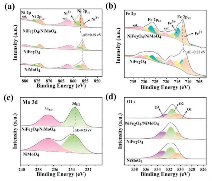
XPS was used to further investigate the surface elemental composition and chemical valence states of the electrocatalysts. The XPS survey spectra in Fig. S6b (Supporting information) displays the presence of Ni, Mo, Fe, C and O elements for NiFe2O4/NiMoO4. Fig. 3a presents the XPS high-resolution spectra of Ni 2p for different electrocatalysts. It can be seen that two main peaks at 856.9 and 874.1 eV are corresponded to Ni 2p3/2 and Ni 2p1/2. The peakfit of the Ni 2p3/2 displays two peaks at 856.9 and 858.5 eV, assigning to the Ni2+ and Ni3+ species, respectively. The relative mole ratio of Ni(+3) to Ni(+2) on the surface was estimated through the area ratio of Ni3+ peak to that of Ni2+ peak [22]. The ratio of Ni3+/Ni2+ of the NiFe2O4/NiMoO4 (0.81) is higher than that of NiFe2O4 (0.75) and NiMoO4 (0.61), indicating that the heterostructure enables the electrocatalyst to have more Ni3+ on the surface. Fig. 3b shows the high-resolution XPS spectra of Fe 2p, the peaks at 712.7 and 726.4 eV correspond to the Fe 2p3/2 and Fe 2p1/2. Two peaks at binding energy of 712.5 and 714. 7 eV are assigned to Fe2+ and Fe3+ of Fe 2p3/2 [36], indicating the presence of Fe3+ and Fe2+ on the surface of NiFe2O4/NiMoO4. The ratio of Fe3+/Fe2+ of the NiFe2O4/NiMoO4 (1.01) is much higher than that of NiFe2O4 (0.67), indicating much more Fe3+ on the surface of the heterostructure. In Fig. 3c, the high-resolution XPS spectra of Mo 3d for NiFe2O4/NiMoO4 show two valence states of Mo3+ and Mo6+. The peak located at 233.4 eV (Mo 3d5/2) is ascribed to Mo3+ in the elelctrocatalyst, which is recognized to be active for HER, and the peaks at 236.6 eV (Mo 3d3/2) is attributed to Mo6+ due to the surface oxidation of the electrocatalyst [37]. Notably, the binding energies of Ni 2p and Fe 2p shift to higher values of 0.69 and 0.22 eV, respectively, while Mo 3d moves to the direction of lower binding energy (shift ~0.23 eV) for NiFe2O4/NiMoO4, which indicates that the Mo doping adjusts the electronic configuration of the Ni and Fe species, and the electrons migrate from Ni and Fe to Mo [30,37–39]. The results indicate the possible formation of (Ni, Fe)OOH [40]. It has been reported that the strong electronic interaction at the interface can modulate the electronic structure to optimize the binding energy of the intermediate, such as *OOH [41], which would facilitate the electron transfer and enhance OER activity [42]. The high-resolution XPS spectra of O 1s (Fig. 3d) reveals the presence of three forms of oxygen, among them, the characteristic peaks at around 530.7, 531.6 and 532.7 eV belong to metal-oxide (O1), metal-hydroxide (O2) and either a partially low coordinated oxygen ion or water adsorbed on the surface due tophysical and chemical interactions (O3), respectively [43].
In order to further elucidate the mechanism of performance improvement, in situ Raman spectroscopy is used to study the active species and surface structure of NiFe2O4/NiMoO4 catalyst (Fig. S7 in Supporting information). As the potential increases during the OER process, a peak corresponding to FeOOH appears at 392 cm-1, and distinct Raman peaks appear at 478 and 554 cm-1, which can be attributed to the Eg Ni-O bending and A1g Ni-O stretching vibration modes of NiOOH, indicating the presence of NiOOH material [44]. In addition, with the increase of applied potential, significant enhancement of peak intensity is observed at 392, 478 and 554 cm-1, indicating that *OOH plays a key role as the main active substance in promoting OER process, which is consistent with the XPS analysis results.
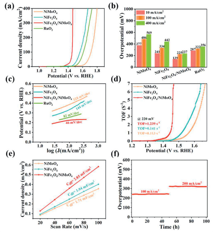
The OER performance of NiMoO4, NiFe2O4, NiFe2O4/NiMoO4 and RuO2 electrocatalyst as working electrodes was assessed using a conventional three-electrode systems in simulated alkaline seawater (1 mol/L KOH + 0.5 mol/L NaCl). In Figs. 4a and b, NiFe2O4/NiMoO4 requires low overpotential of 139 mV to drive the current density of 10 mA/cm2, which is much lower than that of NiMoO4 (377 mV), NiFe2O4 (241 mV) and RuO2 (287 mV). Furthermore, it only requires an overpotential of 237 mV to achieve the current density of 400 mA/cm2, which is much lower than that of NiMoO4 (569 mV), NiFe2O4 (442 mV) and RuO2 (356 mV) and other reported electrocatalysts (Table S1 in Supporting information), demonstrating its superior OER electrocatalytic activity. The result indicates that the plentiful heterostructure interface formed by bimetallic oxides exposes more active sites for enhancing the intrinsic activity. Additionally, the Tafel slopes of different electrocatalysts calculated from the LSV curves serves as an important parameter in electrochemical processes for evaluating the reaction kinetics. As shown in Fig. 4c, the Tafel slope of NiFe2O4/NiMoO4 (46 mV/dec) is significantly smaller than that of NiFe2O4 (144 mV/dec), NiMoO4 (128 mV/dec) and RuO2 (82 mV/dec), which indicates faster reaction kinetics for OER and decreasing the reaction overpotential [22,45]. More importantly, the TOF of NiFe2O4/NiMoO4 electrode at an overpotential of 220 mV is 1.239 s-1, which is much higher than that of NiMoO4 (0.113 s-1) and NiFe2O4 (0.141 s-1), suggesting that the electrocatalyst has more active sites and improves catalytic performance (Fig. 4d). The electrochemical surface area (ECSA) is a crucial parameter for assessing the electrocatalytic performance of various electrodes in the reaction process (Fig. S8 in Supporting information), which was calculated using Cdl. Fig. 4e shows current densities and scan rates have a strong linear connection, and the calculated Cdl value of NiFe2O4/NiMoO4 is 2.85 mF/cm2, which is higher than that of NiMoO4 (1.71 mF/cm2) and NiFe2O4 (1.94 mF/cm2), respectively. The stability is another important factor determining the catalytic performance of electrocatalysts for seawater decomposition, as the abundant salts in seawater are highly corrosive. Fig. 4f is the durability of the NiFe2O4/NiMoO4 electrode evaluated at 100 and 200 mA/cm2 by multistep chronopotentiometry. It has no significant change in voltage after 100 h of continuous stability testing, illustrating the NiFe2O4/NiMoO4 electrocatalyst has excellent stability. Therefore, the above results illustrate NiFe oxide and oxy(hydroxide) on the anode surface are the active sites that are not only responsible for the excellent OER performance, but also contribute to the superior chlorine corrosion-resistance [37]. Additionally, the self-supported three-dimensional heterostructure offers abundant active sites, efficient charge transfer and rapid gaseous product releasing, which also account for the promoted OER [46].
The HER electrocatalytic performance of NiFe2O4/NiMoO4 was also compared with NiMoO4, NiFe2O4 and Pt/C in simulated alkaline seawater. In the HER polarization curves of different electrodes (Fig. 5a), NiFe2O4/NiMoO4 requires low overpotential of 37 mV to drive the current density of 10 mA/cm2, which exhibits higher electrocatalytic activity compared with NiMoO4 (166 mV), NiFe2O4 (150 mV) and Pt/C (45 mV). Notably, NiFe2O4/NiMoO4 only requires an overpotential of 292 mV to drive the current density of 400 mA/cm2 for the HER, which is much lower than that of NiMoO4 (525 mV), NiFe2O4 (498 mV) and Pt/C (372 mV) (Fig. 5b), which exceeds most reported catalysts (Table S2 in Supporting information). The interaction between NiMo and NiFe can alter the Gibbs free energy during the reaction process, thereby altering catalytic activity [37]. In Fig. 5c, the Tafel slopes of different electrodes are 92 mV/dec (NiFe2O4/NiMoO4), 194 mV/dec (NiMoO4), 168 mV/dec (NiFe2O4) and 96 mV/dec (Pt/C), respectively. Thereinto, NiFe2O4/NiMoO4 has the smallest Tafel slope, implying it appears the fastest HER electrocatalytic kinetics.
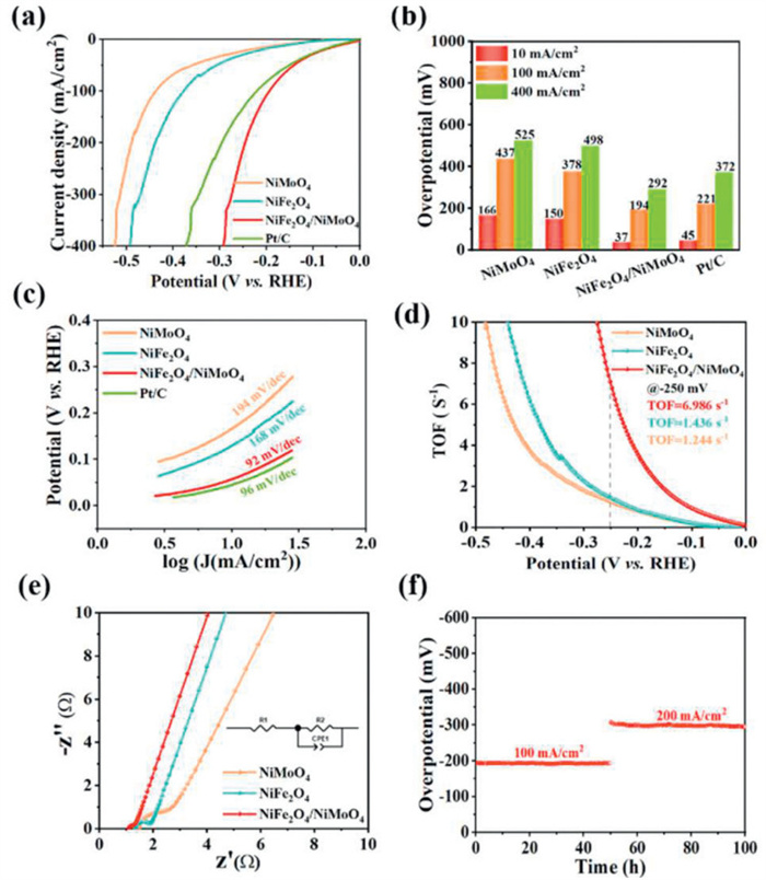
Moreover, the TOF of HER for NiFe2O4/NiMoO4 at the overpotential of 250 mV is 6.986 s-1 (Fig. 5d), which is much higher than that of NiFe2O4 (1.436 s-1) and NiMoO4 (1.244 s-1), demonstrating the advantages of NiFe2O4/NiMoO4 with efficient active sites and heterostructures for the electrocatalytic HER in simulated alkaline seawater media. The EIS measurements were conducted to evaluate the charge transfer capability of the electrocatalysts (Fig. 5e). Compared with NiMoO4 (0.8 Ω) and NiFe2O4 (1.5 Ω), NiFe2O4/NiMoO4 (0.4 Ω) has the lowest charge transfer resistance (Rct), meaning that NiFe2O4/NiMoO4 possesses a faster charge transfer capability, which in turn can accelerate the electrocatalytic kinetics in the HER process [47]. In Fig. 5f, the overpotential fluctuations of the NiFe2O4/NiMoO4 electrocatalyst at 100 and 200 mA/cm2 are small and almost unchanged within 100 h, suggesting that the abundant interfacial heterostructures in NiFe2O4/NiMoO4 can expand the active sites and ensure sufficient accessibility of the electrolytes to enhance its intrinsic HER electrocatalytic activity and stability [48,49].
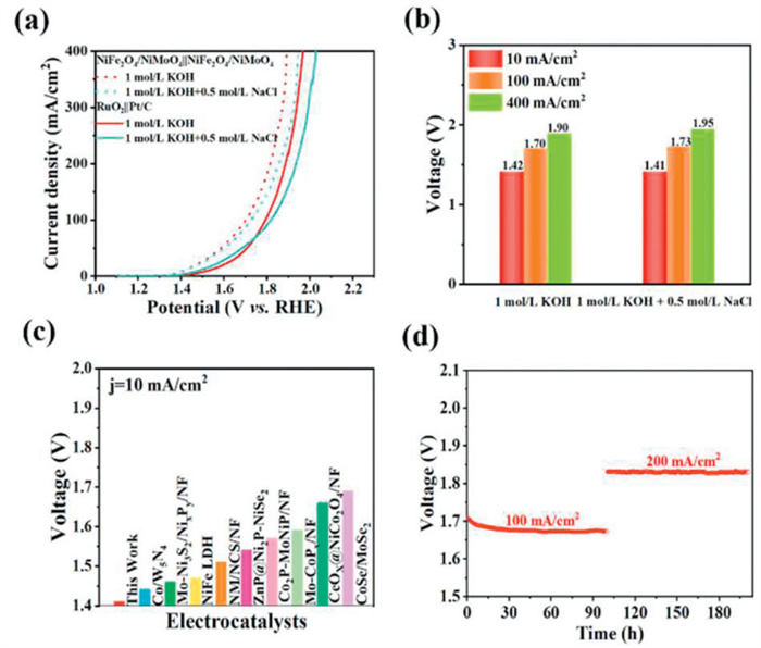
The overall seawater splitting using NiFe2O4/NiMoO4 as cathode and anode is carried out in a two-electrode system. As shown in Figs. 6a and b, NiFe2O4/NiMoO4||NiFe2O4/NiMoO4 pair requires 1.41 and 1.95 V of potentials to drive 10 and 400 mA/cm2 of current densities in simulated alkaline seawater (1 mol/L KOH + 0.5 mol/L NaCl), which is much lower than that of RuO2||Pt/C (1.49 and 2.03 V), showing better electrocatalytic performance compared with commercial electrode pairs and reported bifunctional electrocatalysts (Fig. 6c). Moreover, the potential stability of NiFe2O4/NiMoO4||NiFe2O4/NiMoO4 pair remains almost unchanged at 100 and 200 mA/cm2 for 200 h in simulated alkaline seawater (Fig. 6d). Obviously, the NiFe2O4/NiMoO4 exhibits excellent overall seawater splitting performance in alkaline electrolyte. Furthermore, the chlorine (hypochlorite) visual test kit was used to check the color of the electrolyte during 6 h seawater electrolysis process at 20 mA/cm2. As shown in Fig. S9 (Supporting information), the color of the glass bottle remains transparent, demonstrating that no hypochlorite is generated in the electrolyte.
At a fixed current of 10 mA/cm2, the generated H2/O2 gases from the electrolyzes are collected using an upward-delivery cylinder method for measurement faradaic efficiency (Fig. S10 in Supporting information). In Fig. S11 (Supporting information), the volume ratio of H2 and O2 gases is close to 2:1, and the total Faradaic efficiency is determined to be around 99%, which is greatly favorable during simulated alkaline seawater splitting. The above results show that NiFe2O4/NiMoO4 has high electrocatalytic activity and stability in simulated alkaline seawater, which indicates the heterogeneous electrocatalysts have potential applications for overall seawater splitting. Furthermore, the XPS analysis was carried out to investigate the surface chemical composition of NiFe2O4/NiMoO4 used at anode (Fig. S12 in Supporting information). It can be seen that much more Ni3+ and Fe3+ were formed on the surface of the NiFe2O4/NiMoO4 electrocatalyst after OER [50]. Additionally, the relative molar ratio of Ni(+3) to Ni(+2) on the surface was estimated by the area ratio of Ni3+ peak to that of Ni2+ peak, and the Ni3+/Ni2+ ratio of NiFe2O4/NiMoO4 after OER is found to be 1.01, which is higher than the previous OER of 0.81, also the Fe3+/Fe2+ ratio is increased from 1.01 to 1.34 after testing. It can be deduced that the NiFe2O4/NiMoO4 heterostructure facilitates the formation of high valence states Ni3+ and Fe3+ species (such as NiOOH/FeOOH), which can further improve the intrinsic activity of electrocatalyst during OER [51,52].
To investigate the influence of different electrolytes on electrocatalytic performance, the OER and HER performance in actual seawater (1 mol/L KOH + seawater) were tested respectively [53–55]. In Fig. S13a (Supporting information), NiFe2O4/NiMoO4 requires low overpotentials of 305 and 341 mV for OER to reach 100 and 400 mA/cm2, respectively, which is much lower than that of RuO2 (498 mV) at high current density (400 mA/cm2), indicating remarkable activity of NiFe2O4/NiMoO4 towards seawater splitting at industrial current density. In Fig. S13b (Supporting information), the required overpotentials for NiFe2O4/NiMoO4 at 100 and 400 mA/cm2 are 310 and 384 mV, respectively, which is lower than that of other electrocatalysts, demonstrating the excellent HER performance in actual seawater.
Therefore, the as-prepared NiFe2O4/NiMoO4 electrocatalyst not only has excellent HER and OER performance in simulated alkaline seawater, but also maintains superior electrocatalytic activity in actual seawater. Meanwhile, the stability of OER and HER of NiFe2O4/NiMoO4 can maintain within 100 h in actual seawater at 100 mA/cm2 (Figs. S13c and d in Supporting information). In Fig. S13e (Supporting information), the NiFe2O4/NiMoO4||NiFe2O4/NiMoO4 pair requires 1.79 and 2.07 V to drive 10 and 400 mA/cm2 respectively, exhibiting excellent overall seawater splitting performance in actual seawater. Fig. S13f (Supporting information) indicates that the voltage fluctuation of NiFe2O4/NiMoO4 electrocatalyst during the reaction of 100 h at a current density of 100 mA/cm2 is not significant, showing excellent stability of overall seawater splitting. Therefore, the self-supporting NiFe2O4/NiMoO4 electrocatalyst with abundant heterostructure also shows excellent catalytic activity in actual seawater, and has good corrosion resistance to chloride ions in seawater.
In this work, an effective synthetic method for preparing self-supported NiFe2O4/NiMoO4 heterostructure for alkaline seawater splitting has been demonstrated. The electrocatalyst exhibits excellent HER and OER electrochemical activity, and the NiFe2O4/NiMoO4||NiFe2O4/NiMoO4 pair only requires 1.41 and 1.95 V at the current density of 10 and 400 mA/cm2 with excellent stability and corrosion resistance in alkaline seawater. The enhanced electrochemical performance and robust stability of the NiFe2O4/NiMoO4 electrode can be mainly attributed to the 1D NiMoO4 nanowires afforded large surface area, the NiFe2O4 nanoparticles decorated on NiMoO4 forms abundant interfaces of NiFe2O4/NiMoO4, self-supported three-dimensional structure using CF as substrate has excellent mechanical and electrical properties, which ensure efficient charge transfer, expand the effective active surface area, expose more active sites and ensure that the electrolyte fully contacts highly dispersed active sites during electrocatalytic processes. In addition, the electronic interaction at the interface adjusts the electronic structure, optimizes the charge distribution, and facilitates the formation of more active sites, thereby enhancing the intrinsic activity of catalysts. This work demonstrates new methods for constructing excellent heterogeneous electrocatalysts for hydrogen production in alkaline seawater for industrial applications.
The authors declare that they have no known competing financial interests or personal relationships that could have appeared to influence the work reported in this paper.
Lili Wang: Writing – review & editing, Supervision, Project administration, Funding acquisition, Data curation, Conceptualization. Xujie Han: Writing – original draft, Project administration, Investigation, Formal analysis, Data curation. Baichuan Xiong: Writing – review & editing, Supervision. Ya Yan: Validation, Supervision, Funding acquisition, Data curation. Cheng Zhang: Writing – review & editing, Supervision. Yuning Qu: Writing – review & editing, Supervision. Yiran Zhang: Writing – original draft, Methodology, Investigation, Formal analysis, Data curation. Linlin Zheng: Writing – original draft, Methodology, Formal analysis, Data curation. Zirui Gao: Writing – review & editing, Supervision. Shuheng Tian: Writing – review & editing, Supervision. Wenjing Dai: Writing – review & editing, Validation. Bowen Cheng: Writing – review & editing, Supervision. Hang Zhang: Writing – review & editing, Supervision. Zhen Yin: Writing – review & editing, Supervision, Formal analysis, Data curation, Conceptualization.
This work was supported by the National Natural Science Foundation of China (No. 51908408), the Science & Technology Development Fund of Tianjin Education Commission for Higher Education (No. 2019KJ008) and Basic Research Program of Jiangsu Province (No. BK20241845).
Supplementary material associated with this article can be found, in the online version, at doi:
H. Wei, J. Si, L. Zeng, et al., Chin. Chem. Lett. 34 (2023) 107144. doi: 10.1016/j.cclet.2022.01.037
M. Liu, G. Lv, H. Liu, et al., Chin. Chem. Lett. 35 (2024) 108459. doi: 10.1016/j.cclet.2023.108459
B.J. Zhang, B. Chang, S.P. Qiu, et al., Rare Met. 43 (2024) 2613–2622. doi: 10.1007/s12598-023-02587-4
W. Dai, X. Wang, Y. Ma, et al., Nano Res. 18 (2025) 94907061. doi: 10.26599/nr.2025.94907061
Y.J. Lee, S.K. Park, Rare Met. 43 (2023) 522–532.
D. Li, Z. Li, R. Zou, et al., Appl. Catal. B: Environ. 307 (2022) 121170. doi: 10.1016/j.apcatb.2022.121170
H. Luo, J. Liang, J. Zhou, et al., New J. Chem. 46 (2022) 7999–8009. doi: 10.1039/d2nj00867j
D. Wang, Q. Li, C. Han, et al., Nat. Commun. 10 (2019) 3899. doi: 10.1038/s41467-019-11765-x
M.Y. Yang, J. Yuan, X.L. Fu, et al., Rare Met. 43 (2024) 2636–2647. doi: 10.1007/s12598-024-02625-9
Z. Peng, Q. Zhang, G. Qi, et al., Chin. J. Struct. Chem. 43 (2024) 100191.
X. Hang, R. Yang, Y. Xue, et al., Chin. Chem. Lett. 34 (2023) 107787. doi: 10.1016/j.cclet.2022.107787
C. Ros, S. Murcia-López, X. Garcia, et al., ChemSusChem 14 (2021) 2872–2881. doi: 10.1002/cssc.202100194
Z. Yu, L. Liu, Adv. Mater. 36 (2023) 2308647.
C. Wang, M. Zhu, Z. Cao, et al., Appl. Catal. B: Environ. 291 (2021) 120071. doi: 10.1016/j.apcatb.2021.120071
J. Xia, L. Zhang, Y. Wang, et al., Inorg. Chem. Front. 11 (2024) 1153–1166. doi: 10.1039/d3qi02222f
Y. Yang, M. Lin, Y. Wu, et al., J. Colloid Interf. Sci. 647 (2023) 510–518. doi: 10.3390/land12020510
M. Ning, L. Wu, F. Zhang, et al., Mater. Today Phys. 19 (2021) 100419. doi: 10.1016/j.mtphys.2021.100419
W. Dai, L. Luo, Z. Yin, Chin. J. Struct. Chem. 44 (2025) 100442.
Y. Zhao, H. Zhang, J. Chen, et al., Chem. Eng. J. 477 (2023) 147092. doi: 10.1016/j.cej.2023.147092
W. Shi, J. Zhu, L. Gong, et al., Small 18 (2022) 2205683. doi: 10.1002/smll.202205683
A. Wang, J. Chen, P. Zhang, et al., Acta Phys. Chim. Sin. 0 (2023) 2301023. doi: 10.3866/pku.whxb202301023
J. Li, L. Wang, H. He, et al., Nano Res. 15 (2022) 4986–4995. doi: 10.1007/s12274-022-4144-6
C.F. Li, L.J. Xie, J.W. Zhao, et al., Appl. Catal. B: Environ. 306 (2022) 121097. doi: 10.1016/j.apcatb.2022.121097
Z. Song, Y. Jiang, Q. Gou, et al., Chin. Chem. Lett. 36 (2025) 109793. doi: 10.1016/j.cclet.2024.109793
H. Li, C. Cai, Q. Wang, et al., Chem. Eng. J. 435 (2022) 134860. doi: 10.1016/j.cej.2022.134860
Y. Chen, Q. Liu, Y. Yao, et al., ACS Appl. Energy Mater. 4 (2021) 9858–9865. doi: 10.1021/acsaem.1c01884
X. Cao, R. Fan, J. Zhou, et al., Chem. Commun. 58 (2022) 1569–1572. doi: 10.1039/d1cc06409f
R.S. Alkhaldi, M.A. Gondal, M.J.S. Mohamed, et al., ACS Appl. Nano Mater. 7 (2024) 2867–2878. doi: 10.1021/acsanm.3c05156
A.I. Inamdar, H.S. Chavan, Y. Jo, et al., Int. J. Energ. Res. 45 (2021) 16963–16972. doi: 10.1002/er.6934
S. Qiu, B. Zhang, X. Wang, et al., J. Colloid Interf. Sci. 641 (2023) 277–288. doi: 10.1016/j.jcis.2023.03.003
G. Zhao, B. Wang, Q. Yan, et al., J. Alloys Compd. 902 (2022) 163738. doi: 10.1016/j.jallcom.2022.163738
C. Huang, Z. Xia, J. Wang, et al., Nano Res. 17 (2023) 1066–1074.
S.M. Ji, H. Jun, J.S. Jang, et al., J. Photoch. Photobio. A 189 (2007) 141–144. doi: 10.1016/j.jphotochem.2007.01.011
X.L. Huong, M. Bechelany, M. Cretin, Carbon 122 (2017) 564–591. doi: 10.1016/j.carbon.2017.06.078
D. Guo, Y. Luo, X. Yu, et al., Nano Energy 8 (2014) 174–182. doi: 10.1016/j.nanoen.2014.06.002
X. Zhang, Z. Zhang, S. Sun, et al., RSC Adv. 8 (2018) 15222–15228. doi: 10.1039/c8ra02559b
L. Yu, Q. Zhu, S. Song, et al., Nat. Commun. 10 (2019) 5106. doi: 10.1038/s41467-019-13092-7
J. Wang, S. Qing, X. Tong, et al., Appl. Surf. Sci. 640 (2023) 158330. doi: 10.1016/j.apsusc.2023.158330
Q. Lv, B. Yao, W. Zhang, et al., Chem. Eng. J. 446 (2022) 137420. doi: 10.1016/j.cej.2022.137420
G.F. Chen, T.Y. Ma, Z.Q. Liu, et al., Adv. Funct. Mater. 26 (2016) 3314–3323. doi: 10.1002/adfm.201505626
Z. Xue, X. Li, Q. Liu, et al., Adv. Mater. 31 (2019) 1900430. doi: 10.1002/adma.201900430
J. Zhang, T. Wang, D. Pohl, et al., Angew. Chem. Int. Ed. 55 (2016) 6702–6707. doi: 10.1002/anie.201602237
L. Wang, Y. Yan, R. Li, et al., Chin. Chem. Lett. 35 (2024) 110011. doi: 10.1016/j.cclet.2024.110011
K. Ding, J. Hu, L. Zhao, et al., Nano Energy 121 (2024) 109270. doi: 10.1016/j.nanoen.2024.109270
Y. Zhang, B. Feng, M. Yan, et al., Nano Res. 17 (2023) 3769–3776.
Q. Wu, Q. Gao, B. Shan, et al., Acta Phys. Chim. Sin. 39 (2023) 2303012. doi: 10.3866/pku.whxb202303012
M. Guo, A. Qayum, S. Dong, et al., J. Mater. Chem. A 8 (2020) 9239–9247. doi: 10.1039/d0ta02337j
D. Guo, Z. Zhao, M.Y. Zong, et al., ACS Sustain. Chem. Eng. 11 (2023) 8362–8373. doi: 10.1021/acssuschemeng.3c01554
P. He, X.Y. Yu, X.W. Lou, Angew. Chem. Int. Ed. 56 (2017) 3897–3900. doi: 10.1002/anie.201612635
L. Wang, D. Wang, L. Zheng, et al., Nano Res. 17 (2024) 9472–9482. doi: 10.1007/s12274-024-6850-8
Y. Liu, S. He, Y. Chen, et al., J. Power Sources 506 (2021) 230097. doi: 10.1016/j.jpowsour.2021.230097
L. Yu, L. Wu, B. McElhenny, et al., Energy Environ. Sci. 13 (2020) 3439–3446. doi: 10.1039/d0ee00921k
R. Andaveh, A.S. Rouhaghdam, J. Ai, et al., Appl. Catal. B: Environ. 325 (2023) 122355. doi: 10.1016/j.apcatb.2022.122355
L. Shao, X. Han, L. Shi, et al., Adv. Energy Mater. 14 (2023) 2303261.
W. Yu, H. Liu, Y. Zhao, et al., Nano Res. 16 (2023) 6517–6530. doi: 10.1007/s12274-022-5369-0

Figure 1 Schematic illustration of the synthesis of 1D self-supporting NiFe2O4/NiMoO4 heterostructure on CF.

Figure 2 (a, b) SEM images of NiFe2O4/NiMoO4, (c) TEM image, (d) HRTEM image and (e) STEM image and the corresponding EDS elemental mapping spectra of NiFe2O4/NiMoO4.

Figure 3 XPS spectra of (a) Ni 2p, (b) Fe 2p, (c) Mo 3d and (d) O 1s for different electrocatalysts.

Figure 4 (a) LSV curves for OER, (b) histogram of corresponding overpotential at different current densities, (c) Tafel plots, (d) TOF and (e) Cdl plots of NiMoO4, NiFe2O4 and NiFe2O4/NiMoO4 electrocatalysts. (f) Chronoamperometric curves of NiFe2O4/NiMoO4 electrocatalyst at 100 and 200 mA/cm2 for OER in simulated alkaline seawater (1 mol/L KOH + 0.5 mol/L NaCl).

Figure 5 (a) LSV curves for HER, (b) histogram of corresponding overpotential at different current densities, (c) Tafel plots, (d) TOF and (e) Nyquist plots of NiMoO4, NiFe2O4 and NiFe2O4/NiMoO4 electrocatalysts. (f) Chronoamperometric curves of NiFe2O4/NiMoO4 at 100 and 200 mA/cm2 for HER in simulated alkaline seawater (1 mol/L KOH + 0.5 mol/L NaCl).

Figure 6 (a) Overall seawater splitting of NiFe2O4/NiMoO4‖NiFe2O4/NiMoO4 and Pt/C‖RuO2. (b) Corresponding voltages at j = 10, 100 and 400 mA/cm2. (c) Splitting voltages comparison of different electrodes. (d) Chronoamperometric curve of NiFe2O4/NiMoO4‖NiFe2O4/NiMoO4 at 100 and 200 mA/cm2 in simulated alkaline seawater (1 mol/L KOH + 0.5 mol/L NaCl).

 扫一扫看文章

扫一扫关注我们
 DownLoad:
 下载:
下载: