In-situ Z-scheme hetero-phase homojunction significantly enhances the carrier separation efficiency of TiO2 nanotube arrays: Key role of crystal phase engineering
Citation:
Bicheng Ji, Xicheng Li, Shuai Gao, Pengyuan Liu, Jiajie Bao, Lv Qian, Changzheng Wang, Qiang Wang, Chong-Chen Wang. In-situ Z-scheme hetero-phase homojunction significantly enhances the carrier separation efficiency of TiO2 nanotube arrays: Key role of crystal phase engineering[J]. Chinese Chemical Letters,
2026, 37(2): 111424.
doi:
10.1016/j.cclet.2025.111424
In-situ Z-scheme hetero-phase homojunction significantly enhances the carrier separation efficiency of TiO2 nanotube arrays: Key role of crystal phase engineering
English
In-situ Z-scheme hetero-phase homojunction significantly enhances the carrier separation efficiency of TiO2 nanotube arrays: Key role of crystal phase engineering
Beijing Key Laboratory of Functional Materials for Building Structure and Environment Remediation, Beijing University of Civil Engineering and Architecture, Beijing 100044, China
b.
Laboratory for Micro-sized Functional Materials & College of Elementary Education and Department of Chemistry, Capital Normal University, Beijing 100048, China
Received Date:
27 December 2024 Accepted Date:
06 June 2025 Revised Date:
29 March 2025 Available Online:
15 February 2026
Abstract:
Light-energy-driven semiconductor catalysis offers attractive ways to address environmental and energy crises. TiO2 is the most promising catalyst for photocatalysis, but the lack of charge-carrier separation efficiency severely limits its catalytic performance. In this study, we carried out crystal phase engineering to prepare in situ Z-scheme hetero-phase homojunction of anatase-rutile and clarified the structure-performance relationship. The efficiency of sulfamerazine removal by hetero-phase homojunction TiO2 nanotube arrays in a single-compartment photocatalytic fuel cell system was improved by 1.93 times compared to conventional anatase TiO2 nanotube arrays and the degradation pathways were revealed by the Fukui function combined with HP-LCMS. The successful construction of Z-scheme hetero-phase homojunction was confirmed by Raman, X-ray diffraction (XRD), and electron spin resonance (ESR), which combined with density functional theory (DFT) calculations revealed the key role of crystal phase engineering in the construction of hetero-phase homojunction. This work provides a novel strategy for the scientific design of titanium dioxide photocatalysts.
Harnessing solar energy to degrade organic pollutants on semiconductor photocatalysts presents a promising solution to the global environmental and energy crises [1-3]. Photocatalytic fuel cell (PFC), evolved from photoelectrochemical cell (PEC) [4], represent an advanced technology that utilizes solar energy for simultaneous wastewater treatment and electricity generation [5, 6]. This technology offers the potential to convert waste resources into clean energy, benefiting both environmental sustainability and energy needs. In PFC systems, photoexcited electrons that transition to the conduction band can migrate from the photoanode to the cathode via an external potential generated by the mismatched Fermi levels of the two electrodes, facilitating water and oxygen reduction reactions [7]. Concurrently, the highly oxidative photoinduced holes left in the valence band can oxidize pollutant molecules and water to generate reactive oxygen species (ROS) such as hydroxyl radicals, further degrading organic pollutants [8-12]. As the photoanode in these systems plays a crucial role in generating photogenerated carriers (electrons and holes) to drive the degradation of organic pollutants, its development is key to enhancing the efficiency of PFC technology.
TiO2, with its low cost, non-toxicity, and strong UV-driven activity, has become one of the most extensively studied photocatalysts [13-15]. TiO2 nanotube arrays (TNAs) possess a relatively large surface area, high physicochemical and mechanical stability, and directional electron transport capabilities, which reduce the recombination of photogenerated charges, making them ideal photoanode materials for PFC [16-19]. However, despite improvements in reaction conditions offered by TNAs and PFC systems over traditional powder photocatalysis, the inherent low carrier separation efficiency of TiO2 catalysts results in unsatisfactory photocatalytic activity [20]. Therefore, scientific modulation of the structure and charge transport pathways of TiO2 is essential to improving the utilization efficiency of solar energy.
Numerous methods have been explored to enhance photogenerated carrier separation efficiency. These design strategies can be broadly classified into constructing defects [21, 22], introducing energy levels (via doping elements [23, 24]) and promoting spatial separation of carriers (through loading metals [25, 26] or constructing heterojunctions [27-29]). However, it is worth noting that the contact interfaces formed by different materials may have limitations in terms of stability under oxidation and light exposure conditions. Employing appropriate methods to induce in situ phase transformation of the catalyst and leveraging the intrinsic properties of different phases to enhance catalyst performance is a promising design approach for achieving spatial separation of carriers. Previous studies reported that phase junctions formed between anatase and rutile TiO2 effectively extend carrier lifetimes, and found that an anatase-to-rutile ratio of approximately 9:1 in TiO2 achieved satisfactory efficiency and selectivity in methane aerobic oxidation to formaldehyde [30]. Notably, the design of crystal phases in TiO2 nanotube arrays photoanodes has not been sufficiently addressed in the context of photocatalytic oxidation reactions within PFC systems. The mechanisms by which charge transport pathways among different crystal phases affect PFC performance remain unclear, hindering the scientific understanding of the structure-performance relationship in crystal phase engineering strategies for photoanode catalyst design.
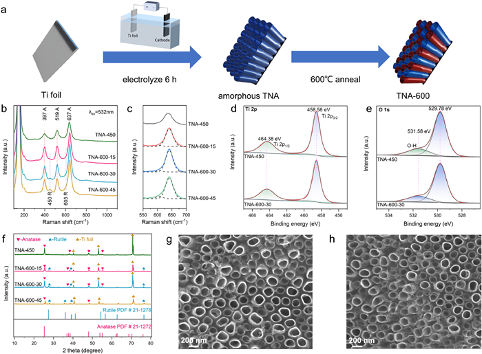
In the present work, the hetero-phase homojunction TNAs were prepared by annealing amorphous TNAs, produced via anodization, in air at 600 ℃ for controlled durations (Fig. 1a). The samples were annealed at 450 ℃ for 30 min, designated as TNA-450. Another batch was annealed at 600 ℃ for 15, 30, and 45 min at a heating rate of 5 ℃/min, designated as TNA-600–15, TNA-600–30, and TNA-600–45, respectively. The Raman spectra (Figs. 1b and c) show peaks at 397, 519, and 637 cm−1, corresponding to the B1g, A1g, and Eg modes of the anatase phase, respectively. When annealed at 600 ℃, additional peaks at 450 and 603 cm−1 appear, indicative of the rutile phase Eg and A1g modes, with the intensity of these peaks increasing with longer annealing time. X-ray photoelectron spectroscopy (XPS) analysis (Figs. 1d and e) showed no shift in Ti 2p or O 1s peaks, indicating stable surface chemical properties and no oxygen vacancies. Full-spectrum XPS data (Fig. S1 in Supporting information) further demonstrated that rutile phase formation resulted from anatase transformation, with no change in the overall titanium dioxide composition. X-ray diffraction (XRD) patterns (Fig. 1f) revealed that TNA-450 exhibited purely anatase phases with sharp diffraction peaks, while TNA-600 samples annealed at 600 ℃ displayed both anatase and rutile phases. Prolonged annealing at 600 ℃ increased rutile content (from 8.60% to 18.91%) and decreased anatase content (from 91.40% to 81.09%) (Table S1 in Supporting information). Additional rutile diffraction peaks appeared, while certain anatase peaks diminished, indicating a gradual phase transformation with extended annealing. Scanning electron microscope (SEM) images (Figs. 1g and h) showed that the nanotube diameter (120–150 nm), tube density (about 2.75 × 10⁹ tubes/cm2), wall thickness (14–15 nm), and inter-tube spacing (80–100 nm) remained consistent for both TNA-450 and TNA-600–30. This stability confirms that annealing does not significantly affect the morphology or structural integrity of the nanotubes, enabling the successful preparation of hetero-phase homojunction TNAs with tunable rutile phase proportions.
Figure 1
Figure 1.
Synthesis and characterization of TNAs. (a) Synthesis strategy of TNA-450 and TNA-600. (b, c) Raman spectra. (d, e) XPS spectra of Ti 2p and O 1s for TNA-450 and TNA-600–30. (f) XRD Pattern of TNAs. (g, h) SEM image of TNA-450 and TNA-600–30.
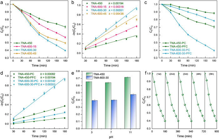
Sulfamerazine (SMR), one of the sulfonamides among five major antibiotics commonly found as emerging pollutants, was used as a model pollutant to evaluate the catalytic performance of TNAs photoanode samples annealed for different durations. Fig. 2a shows the degradation efficiency of SMR by different TNAs photoanodes in the PFC system. Since SMR can hardly be adsorbed to TNAs, dark adsorption degradation is unnecessary. Upon illumination, the degradation efficiency of SMR by the TNA-600 photoanodes was significantly higher than that of TNA-450 (about 1.93 times). The hetero-phase homojunction TNAs achieved more complete and faster degradation of SMR in the PFC system compared to the pure anatase phase TNAs (Fig. 2b). Moreover, the degradation efficiency of TNA-600–30 was notably superior to that of TNA-600–15 and TNA-600–45, indicating that the mixed ratio of the two crystal phases in TNAs significantly affects the degradation performance. This could be attributed to the insufficient growth of the rutile phase in TNA-600–15, which fails to form effective charge transfer pathways, while the excessive transformation of the anatase phase to the rutile phase in TNA-600–45 reduces the number of active sites. Although 180 min of degradation is sufficient to evaluate the superior performance of TNA-600–30, we extended the degradation time to determine the time required to reach the degradation limit. As shown in Fig. S11 (Supporting information), the degradation process reached equilibrium after 5 h, with a degradation rate of 70.6% for TNA-600–30, while the degradation rate for TNA-450 was only 34.2%, further widening the degradation rate gap. The initial pH for evaluating degradation efficiency in the laboratory is 6.8. After the degradation process, the pH of the solution slightly increased to 7.6, probably due to the generation of alkaline products like NH3.
Figure 2
Figure 2.
(a) Degradation efficiency of SMR by different TNAs photoanodes in PFC system (C0 = 10 mg/L). (b) Pseudo-first-order kinetics curve of different TNAs photoanodes in PFC system. (c) Degradation efficiency of SMR by two kinds of photoanode in different systems (C0 = 10 mg/L). (d) Pseudo-first-order kinetics curve of different TNAs photoanode in different systems. (e) Effect of initial solution pH on SMR degradation. (f) The degradation efficiency of SMR by TNA-600–30 for 5 cycles.
The PFC system has the advantage of spatially separating photogenerated electrons and holes compared to traditional powder photocatalysis systems. Comparing the degradation performance of SMR in the PFC system with the traditional PC (photocatalysis) system (Fig. 2c), using TNA-600–30 as a PFC system example, the degradation rate of SMR in the PFC system was approximately 2.84 times higher than that in the traditional PC system. The fitted pseudo-first-order rate constants (Fig. 2d) indicate that the PFC system has a faster degradation rate than the PC system. This phenomenon can be attributed to the formation of the self-bias potential due to the Fermi level difference between the anode and cathode in the closed circuit of the PFC system. This promotes the transfer of electrons from the photoanode to the cathode through the external circuit, enhancing the separation efficiency of external carriers and improving the degradation performance of the photocatalyst within the system.
Catalysts for practical applications must address factors present in real water environments. To evaluate the degradation efficiency of the prepared photoanode catalysts across a wide pH range, experiments were conducted at pH values of 3, 7, and 11, representing acidic, neutral, and alkaline conditions. Fig. 2e shows that the PFC system exhibited strong resistance to pH interference, with improved performance in acidic conditions due to the positive surface charge of TiO2 attracting negatively charged SMR molecules. In contrast, degradation efficiency decreased in alkaline conditions as the negative surface charge repelled pollutants. The TNA-600–30 photoanode outperformed TNA-450, likely due to enhanced electron-hole pair separation in the homojunction, facilitating hydroxyl radical generation for stable pollutant degradation.The stability of TNA-600–30 was verified through five cycles of SMR degradation under identical conditions, with consistent performance after each cycle (Fig. 2f). Post-reaction analysis using XRD (Fig. S2 in Supporting information) confirmed the retention of anatase and rutile phase peaks without impurity formation, indicating stable phase composition. SEM images (Fig. S3 in Supporting information) revealed no significant changes in material morphology after five cycles, with tube density (about 2.73 × 10⁹ tubes/cm2), wall thickness (about 14 nm), and tube diameter (120–150 nm) remaining consistent. These results highlight the robustness and potential of TNA-600–30 for practical water treatment applications. To evaluate the impact of inorganic ions on photocatalytic efficiency, the Box-Behnken design was employed to study their effects on SMR removal [31]. While inorganic cations (e.g., K+, Na+, Ca2+, and Mg2+) have minimal impact [32], the focus was on anions (Cl−, NO3−, SO42−, and H2PO4−). Tables S2 and S3 (Supporting information) detail the ion concentrations and results of 29 SMR removal experiments. A quadratic polynomial model revealed that H2PO4− and Cl− inhibit SMR removal, while SO42− enhances photocatalysis (Fig. S4 in Supporting information). The inhibition by H2PO4− arises from surface passivation of TiO2, hindering active site reactions, while Cl− competes for active sites and forms ClO− under oxidative conditions, reducing SMR oxidation efficiency [33, 34]. SO42−, on the other hand, improves mass transfer in the liquid phase, facilitating oxidation reactions.
The separation and recombination of photogenerated electron-hole pairs (e− h+) in the semiconductor were analyzed through EIS, transient photocurrent measurements, and LSV tests (Fig. S6 in Supporting information). The Nyquist plots of TNA-450 and TNA-600 are shown in Fig. 3a. The Nyquist impedance spectra reflect the charge transfer resistance at the catalyst surface and the interface, with the semicircle radius corresponding to the rate of photocatalytic reactions occurring at the surface. A smaller radius indicates lower surface charge transfer resistance, leading to faster separation and transfer of photogenerated electron-hole pairs. Overall, TNA-600 exhibited lower charge transfer resistance compared to TNA-450, with TNA-600–30 showing the smallest resistance, indicating that the introduction of the rutile phase effectively promotes the separation of photogenerated carriers. As shown in Figs. 3b and c, TNA-600–30 exhibited the highest photocurrent density, and all TNA-600 samples showed higher photocurrent densities than TNA-450, demonstrating that the hetero-phase homojunction of anatase and rutile effectively enhances carrier transfer. The carrier concentration was calculated as shown in Fig. S10 (Supporting information). Given that the anatase phase exhibits superior photocatalytic activity compared to the rutile phase, the carrier concentration was observed to decrease with the reduction in the anatase phase ratio. However, the high carrier separation efficiency of TNA-600–30 promoted the migration of a greater number of carriers to the interface, which consequently led to a significantly improved photocurrent response.
Figure 3
Figure 3.
(a) Nyquist plots, (b) transient photocurrent curves of TNA-450 and TNA-600. (c) LSV curves of TNA-450 and TNA-600 under illumination. (d) J-V curves and corresponding power densities of PFC based on TNA-450 and TNA-600.
Power generation performance of the PFC was evaluated through J-V curves, power density curves, and open-circuit voltage (OCV) measurements. TNA-600 samples showed higher short-circuit currents and maximum power densities than TNA-450, with TNA-600–30 achieving the best performance: A short-circuit current of 20.3 µA/cm2, maximum power density of 4.037 µW/cm2 (Fig. 3d), and significant OCV differences between light and dark conditions (Fig. S5 in Supporting information). The fill factor (FF), a key parameter for energy conversion efficiency [35], ranked TNA-600–30 > TNA-600–45 > TNA-600–15 > TNA-450 (Table S4 in Supporting information), confirming TNA-600–30′s superior power generation capability. These results highlight the advantage of hetero-phase homojunction TNAs over single-phase anatase TNAs as photoanodes in PFC systems.
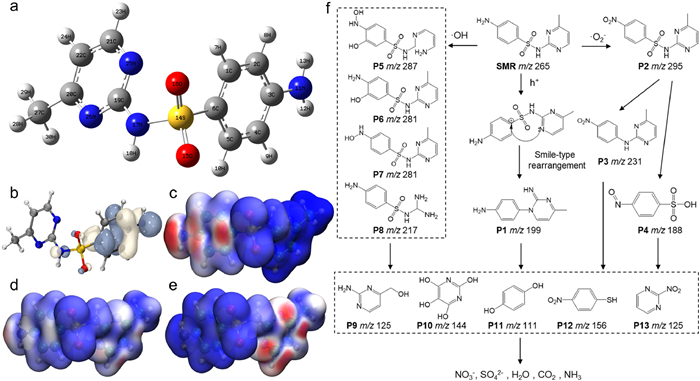
Figs. 4a and b depict the optimized molecular structure and HOMO orbitals of SMR, showing that the HOMO orbitals are concentrated on the benzene ring, amino group, and partially on the nitrogen atom of the sulfonamide group, indicating these regions are electron-donating sites. The Fukui function isosurface diagrams (Figs. 4c-e) and condensed Fukui function values (Table S5 in Supporting information) reveal that electrophilic reactions primarily occur at N11, with additional activity at C2, C4, C6, and C3 on the benzene ring. Nucleophilic sites are concentrated on the pyrimidine ring, particularly at C21, C20, N25, and N26, where holes and •O2− induce ring-cracking reactions. High f0 values confirm these sites' susceptibility to radical attacks by hydroxyl and superoxide radicals. Using Fukui function analysis and HPLC-MS, degradation pathways were elucidated (Fig. 4f). Holes can charge the C6 site, leading to a Smiles rearrangement at N25 and forming intermediate P1. Superoxide radicals target N11, converting the amino group into a nitro group to produce P2. Sulfonamide oxidation removes sulfur, linking the benzene and pyrimidine rings via the amino group to form P3. Further degradation includes pyrimidine ring elimination (P4) and hydroxyl radical-induced reactions at N11 and benzene carbons, yielding intermediates P5-P8. These intermediates undergo oxidative breakdown by ROS into single-ring compounds (P9-P13) and eventually degrade into small molecules such as SO2, NO3−, CO2, H2O and NH3. The toxicity software (Fig. S9 in Supporting information), revealing that most products had lower toxicity than SMR, while a few exhibited higher toxicity. Overall, the degradation of SMR using the PFC system is more beneficial to the ecological environment than its direct release.
Figure 4
Figure 4.
(a) Optimized SMR structure. (b) HOMO, (c) f−, (d) f0 and (e) f+ of SMR. (f) Possible degradation pathways.
To explore the impact of crystal phase ratios on TNA heterojunctions, flat-band potentials were determined using Mott-Schottky analysis (Figs. 5a-d). Increasing annealing time at 600 ℃ shifted flat-band potentials to more negative values, confirming the phase ratio changes of the hetero-phase homojunction. UV–vis spectroscopy (Fig. S7 in Supporting information) and Tauc plots (Fig. S8 in Supporting information) showed that TNA-600–30 had the narrowest bandgap (3.02 eV), extending the photoresponse range. electron spin resonance (ESR) tests identified reactive oxygen species (ROS) generated by TNAs. Under light, TNA-600–30 produced stronger hydroxyl radicals and was capable of generating superoxide radicals, unlike TNA-450 (Figs. 5e and f). Radical quenching experiments (Fig. 5g) revealed that photogenerated holes are the main active species for SMR degradation, with hydroxyl radicals also playing a role. Superoxide radicals contributed significantly only in TNA-600–30, confirming the formation of the hetero-phase homojunction. First-principles calculations (Figs. 5h and i) revealed electron transfer from anatase (work function 6.871 eV) to rutile (7.009 eV), creating a built-in electric field. XPS data reveals no shifts in the Ti 2p binding energy, indicating the absence of significant energy level bending at the interface between the two phases (i.e., no formation of a space charge region). Consequently, combining the widely reported band gap of rutile phase titanium dioxide, the homojunction is identified as Z-type, where photogenerated electrons from the anatase phase transfer to photogenerated holes in the rutile phase for recombination, facilitating redox reactions (Fig. 5j). These findings highlight the enhanced performance of hetero-phase homojunction TNAs in facilitating charge transfer and ROS generation.
Figure 5
Figure 5.
Mott-schottky curve based on (a) TNA-450, (b) TNA-600–15, (c) TNA-600–30 and (d) TNA-600–45. Work function of (e) Anatase (101) crystal facet and (f) Rutile (110) crystal facet. (g) Effect of different scavengers on SMR degradation. (h) •OH ESR spectra of TNAs. (i) •O2− ESR spectra of TNAs. (j) Band plot of hetero-phase homojunction TNAs.
Thus, we propose the degradation mechanism of SMR in PFC systems as depicted in Scheme S2 (Supporting information). Upon illumination on the TNA-600–30 photoanode, electrons in both phases gain energy, transitioning from the valence band to the conduction band and leaving photogenerated holes in the valence band. Due to the Z-scheme hetero-phase homojunction, electrons from the anatase phase combine with holes from the rutile phase, while remaining holes oxidize SMR molecules due to their strong oxidative nature. Water molecules surrounding holes are oxidized to hydroxyl radicals, which synergistically attack SMR molecules, facilitating the degradation reaction. Some photogenerated electrons on the rutile phase not recombined with holes transfer through the self-bias potential between the photoanode and cathode Pt foils in the PFC system, combining with oxygen molecules to generate superoxide radicals, which concurrently degrade pollutants [36]. In traditional photocatalytic systems and catalysts without crystal phase engineering, inefficiency in carrier separation leads to lower degradation efficiency. Furthermore, crystal phase engineering optimizes charge transfer pathways at TNAs hetero-phase homojunction interfaces, forming Z-scheme channels that enhance the generation of oxidizing groups, ultimately enhancing the SMR degradation performance of the PFC system. Under light irradiation, the electrons in different phases of titanium dioxide are excited to the conduction band. The transfer of charge carriers between two conduction bands or between two valence bands is hindered by the internal electric field. In the homojunction, the electrons at the bottom of the conduction band and the holes at the top of the valence band recombine under the driving force of the internal electric field. As a result, electrons accumulate at the higher conduction band edge, participating in reduction reactions, while holes accumulate at the lower valence band edge, participating in oxidation reactions.
In conclusion, we successfully constructed a Z-scheme anatase-rutile homojunction TiO2 nanotube arrays photoanode through simple control of annealing temperature and time. A series of characterizations and performance evaluations confirmed the successful construction of the Z-scheme homojunction. Combining theoretical calculations and experimental results, we revealed the charge transport pathways between different crystal phases and their impact on the performance of the photocatalytic fuel cell system, providing scientific insights into the critical role of crystal phase engineering in the structure-performance relationship. Structurally, the Z-scheme homojunction TNA-600–30 exhibited stronger photoresponse capabilities and higher carrier separation efficiency compared to the anatase-only TNA-450. Applying the synthesized catalyst to the PFC system for the treatment of antibiotic pollutants, specifically sulfamerazine, resulted in a significant enhancement (approximately 1.93 times), aligning with the objective of optimizing catalyst structure through crystal phase engineering. Moreover, the PFC system and the TNA-600–30 photoanode demonstrated excellent reusability and stability, with negligible performance declination and stable morphology and crystal structure after multiple degradation cycles. This confirms the reproducibility and stability of the material for degrading antibiotics in PFC systems. In summary, the Z-scheme hetero-phase homojunction TiO2 nanotube arrays photoanode designed in this study offers a novel approach for the development of photoanodes in future PFC systems and paves the way for a deeper understanding of the mechanisms by which crystal phase engineering influences the structure-activity relationship of catalysts.
Declaration of competing interest
The authors declare that they have no known competing financial interests or personal relationships that could have appeared to influence the work reported in this paper.
This work was supported by the National Natural Science Foundation of China (Nos. 52370025, 52372212), BUCEA Postgraduate Education and Teaching Quality Improvement Project (No. J2023016) and the BUCEA Post Graduate Innovation Project (Nos. DG2023012 and PG2024073).
Supplementary materials
Supplementary material associated with this article can be found, in the online version, at doi:10.1016/j.cclet.2025.111424.
M. Kaneko, H. Ueno, K. Ohnuki, et al., Biosens. Bioelectron. 23 (2007) 140–143. doi: 10.1016/j.bios.2007.03.021
[36]
M.J. Arlos, M.M. Hatat-Fraile, R. Liang, et al., Water Res. 101 (2016) 351–361. doi: 10.1016/j.watres.2016.05.073
Figure 1
Synthesis and characterization of TNAs. (a) Synthesis strategy of TNA-450 and TNA-600. (b, c) Raman spectra. (d, e) XPS spectra of Ti 2p and O 1s for TNA-450 and TNA-600–30. (f) XRD Pattern of TNAs. (g, h) SEM image of TNA-450 and TNA-600–30.
Figure 2
(a) Degradation efficiency of SMR by different TNAs photoanodes in PFC system (C0 = 10 mg/L). (b) Pseudo-first-order kinetics curve of different TNAs photoanodes in PFC system. (c) Degradation efficiency of SMR by two kinds of photoanode in different systems (C0 = 10 mg/L). (d) Pseudo-first-order kinetics curve of different TNAs photoanode in different systems. (e) Effect of initial solution pH on SMR degradation. (f) The degradation efficiency of SMR by TNA-600–30 for 5 cycles.
Figure 3
(a) Nyquist plots, (b) transient photocurrent curves of TNA-450 and TNA-600. (c) LSV curves of TNA-450 and TNA-600 under illumination. (d) J-V curves and corresponding power densities of PFC based on TNA-450 and TNA-600.
Figure 5
Mott-schottky curve based on (a) TNA-450, (b) TNA-600–15, (c) TNA-600–30 and (d) TNA-600–45. Work function of (e) Anatase (101) crystal facet and (f) Rutile (110) crystal facet. (g) Effect of different scavengers on SMR degradation. (h) •OH ESR spectra of TNAs. (i) •O2− ESR spectra of TNAs. (j) Band plot of hetero-phase homojunction TNAs.

 DownLoad:


 下载:
下载:


