School of Environmental Science and Engineering, Shaanxi University of Science and Technology, Xi'an 710021, China
b.
Jiangxi Key Lab of Flexible Electronics, Flexible Electronics Innovation Institute, Jiangxi Science and Technology Normal University, Nanchang 330013, China
Received Date:
01 December 2024 Accepted Date:
16 March 2025 Revised Date:
27 January 2025 Available Online:
15 February 2026
Abstract:
Photoreforming poly(lactic acid) (PLA) plastics into pyruvic acid (PA) coupled with hydrogen evolution is of great significance for sustainable development. However, a significant challenge lies in α-OH bond cleaving of lactic acid (LA). Herein, CdS/Bi4Ti3O12 composite is fabricated, bridged by Bi−S bonds, through in-situ growth of CdS nanoparticles on Bi4Ti3O12 nanoflowers for the successive removal of hydrogen from α-C in LA. In-situ X-ray photoelectron spectroscopy confirms the S-scheme carriers transfer route and interfacial Bi−S bond in CdS/Bi4Ti3O12. Consequently, the photo-electrons and holes with extended lifetimes and strong redox potential accumulate in the CdS conduction band and Bi4Ti3O12 valence band, respectively, as evidenced by in-situ electron spin resonance and time-resolved photoluminescence. This facilitates the generation of •OH radicals, which further participate in the successive dehydrogenation reaction of LA. Consequently, the photoreforming efficiencies of converting PLA into PA and H2 by CdS/Bi4Ti3O12 are 1.7 and 3.16 mmol g–1 h–1, which are respectively 2.8 and 22 times higher than that by pristine Bi4Ti3O12. The present work provides a new approach for designing S-scheme to achieve hydrogen production and value-added conversion of plastics.
Plastic, derived from fossil fuels, has become an integral part of everyday human life [1,2]. Until 2015, it is estimated that > 8.3 billion metric tonnes of plastic have been produced, with most of them (80%) either landfilled or discharged into the natural environment [3,4]. Due to its incredible durability, plastic waste accumulates in the natural environment, leading to a series of environmental issues [5,6]. Polylactic acid (PLA), a type of biodegradable plastic, is expected to address this issue; however, the spontaneous degradation of PLA takes a long time in the natural environment, particularly in ocean water and soil [7,8]. Furthermore, during the degradation process of PLA, CO2 and H2O are generated. This leads to the waste of carbon resources, which is similar to the situation when plastic is incinerated [9]. Consequently, there is a pressing necessity to formulate a highly effective recycling methodology for PLA, so that it can be transformed into chemicals with added value.
Pyruvic acid (PA) has a similar chemical structure to PLA monomer (LA) and is a synthetic raw material for chemical, food, and agricultural products with high commercial value [10]. Therefore, opening a door for converting the PLA into PA is of great significance [9,11]. Recently, a novel photoreforming strategy has attracted enormous interest for its ability to selectively convert PLA plastic waste into pyruvate while producing hydrogen (H2) [12-15]. In the photoreforming PLA process, the H2 is derived from the reduction of protons driven by photogenerated electrons. The pretreated PLA can be regarded as a hole acceptor and is oxidized into pyruvate, while the activation barriers of α-OH bonds in LA restrain the conversion [11,16]. Photocatalysts play a crucial role in the reforming PLA process. However, the problems of low charge separation efficiency and oxidation–reduction ability significantly restrict the production rate of fine chemicals during photoreforming. Therefore, efforts have been made to enhance the separation of photogenerated electron-hole pairs with robust redox capabilities in photocatalysts. The carrier separation ability of a single-component photocatalyst (e.g., TiO2, CdS, and C3N4) and the redox ability of its photogenerated carriers will restrict each other, making it difficult for a single-component photocatalyst [17]. A reasonable design of S-scheme is expected to meet the requirements of efficient separation of photogenerated carriers and strong redox ability of photogenerated carriers [18-20]. Specifically, the internal electric field (IEF) of S-scheme heterojunction promotes the spatial separation of photogenerated carriers, and the photogenerated electrons and holes with strong redox abilities can achieve proton reduction to H2 and selective LA oxidation to PA, respectively [17,21]. However, constructing chemical bonds precisely to achieve efficient electron transfer at the interface for enhanced built-in electric fields remains a challenge.
Herein, we designed CdS/Bi4Ti3O12 (CdS/BTO) S-scheme bridged by Bi−S bonds through in-situ growing CdS nanoparticles onto BTO nanoflowers for the efficient photoreforming of PLA into H2 production and PA. BTO acts as a representative oxidation photocatalyst, demonstrating high abundance, non-toxicity, and excellent chemical stability. Moreover, the oxidation potential of BTO is sufficiently positive to drive photogenerated holes to react with H2O and form •OH, which is then used to attack α-OH in LA. CdS nanoparticles were hybridized with BTO because it is an efficient photocatalyst with visible-light absorption, and it has demonstrated excellent performance in photocatalytic H2 evolution. The S-scheme CdS/BTO heterojunction facilitates the separation and migration of photogenerated charge carriers while preserving the robust redox capacity of the composite photocatalyst. Consequently, the photoreforming efficiencies of converting PLA into PA and H2 by BTO are 1.7 and 3.16 mmol g–1 h–1, which are respectively 2.8 and 22 times higher than that by pristine BTO. This work provides a new approach for designing S-scheme to achieve hydrogen production and the value-added conversion of plastics.
The materials and detailed preparation of catalysts can be found in Supporting information.
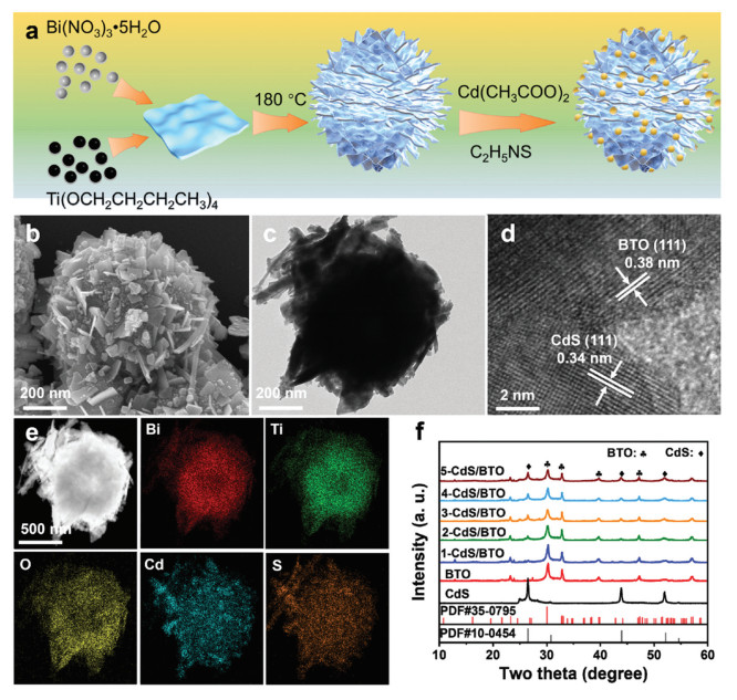
The synthesis of CdS/BTO is illustrated in Fig. 1a. The pristine BTO flowers were synthesized by hydrothermal method. Subsequently, CdS nanoparticles were in-situ grown on BTO surfaces to form x-CdS/BTO hybrid structures, where BTO represents BTO and x signifies the weight percentage of CdS compared to BTO. The Cd contents of 1-CdS/BTO, 2-CdS/BTO, 3-CdS/BTO, 4-CdS/BTO, and 5-CdS/BTO composites were further quantified to be 1.36, 2.52, 3.67, 4.88, and 5.96 wt% using inductively coupled plasma optical emission spectrometry (ICP-OES). The morphology and structure of BTO, CdS, and 3-CdS/BTO were revealed by scanning electron microscopy (SEM) and transmission electron microscopy (TEM). As shown in Figs. 1b and c and Figs. S1a-d (Supporting information), the BTO and CdS exhibit nanoflower and nanoparticle structures, with average diameters of approximately 500 nm and 27 nm, respectively. High-resolution TEM (HRTEM) images of 3-CdS/BTO (Fig. 1d and Figs. S1e and f in Supporting information) show lattice spacings of 0.34 and 0.38 nm, corresponding to the (111) crystal plane of cubic CdS and the (111) crystal plane of monoclinic BTO, respectively [22,23]. As shown in Fig. 1e, the energy-dispersive spectroscopy (EDS) mappings of 3-CdS/BTO demonstrate the homogeneous distribution of Cd, S, Bi, Ti, and O elements. The crystalline structures of pristine BTO, CdS, and 3-CdS/BTO composites were detected by X-ray diffraction (XRD) (Fig. 1f). The characteristic peaks at 26.5°, 30.8°, 43.9°, and 52.0° assign to the (111), (200), (110), and (311) planes of cubic CdS (PDF #10–0454), while the peaks at 23.3°, 30.1°, 32.8°, 39.7°, and 47.3° attribute to the (111), (171), (200), (280), and (202) crystalline planes of BTO (PDF #35–0795). The XRD patterns of all x-CdS/BTO composites show the diffraction peaks of both CdS and BTO. As the CdS content increases, the intensities of CdS-related peaks become slightly stronger, while the intensities of BTO-related peaks decrease due to its lower weight loading and lower crystallinity than those of pristine BTO. Raman shifts of BTO at 848, 544, and 274 cm−1 is attributed to the internal vibrational modes of TiO6 octahedron (Fig. S2 in Supporting information) [24]. Meanwhile, the peaks of CdS at 601 and 301 cm−1 are attributed to the first overtone (2LO) of the A1 mode and longitudinal optical (1LO) phonon mode [25]. The 3-CdS/BTO presents characteristic peaks of both BTO and CdS, while the intensity decreases compared with pristine CdS or BTO. The BET surface areas of BTO, CdS, and 3-CdS/BTO were confirmed by N2 physisorption measurements at 77 K. All photocatalysts exhibit type Ⅳ isotherms with type H3 hysteresis loops, indicating the presence of mesopores (Fig. S3a in Supporting information) [26]. The specific surface areas and mean pore sizes (Fig. S3b in Supporting information) of BTO (12.60 m2/g and 23.0 nm), CdS (13.72 m2/g and 31.2 nm), and 3-CdS/BTO (9.86 m2/g and 24.6 nm) are similar, indicating that the decoration of CdS nanoparticles onto BTO does not destroy the structure of BTO.
Figure 1
Figure 1.
Structure of as prepared heterojunctions. (a) Synthetic process of CdS/BTO. (b) SEM image, (c) TEM image, and (d) HRTEM images of 3-CdS/BTO composites. (e) EDS elemental mappings of Bi, Ti, O, S, and Cd elements in 3-CdS/BTO. (f) XRD patterns of CdS, BTO, and x-CdS/BTO.
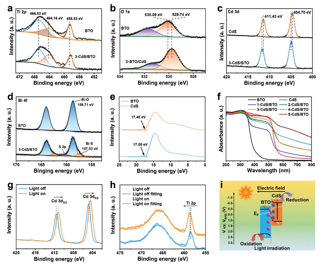
X-ray photoelectron spectroscopy (XPS) was employed to reveal the surface chemical states of the prepared catalysts. Survey XPS spectrum (Fig. S4 in Supporting information) of 3-CdS/BTO validates the distribution of Cd, S, Bi, Ti, and O elements. For the Ti 2p high-resolution spectrum of BTO, peaks at the binding energies of 458.53 and 464.16 eV are attributed to the 2p1/2 and 2p3/2 orbitals (Fig. 2a), respectively. Besides, a peak at higher binding energies results from the overlap between Ti 2p1/2 and Bi 4d3/2 orbitals [27]. The O 1s spectrum (Fig. 2b) of BTO is deconvoluted into two peaks with binding energies of 530.09 and 531.33 eV, which are attributed to the lattice oxygen in BTO and the surface hydroxyls, respectively [28,29]. For CdS, the peaks of Cd 3d3/2 (404.70 eV) and Cd 3d5/2 (411.43 eV) are observed in the Cd 3d spectrum (Fig. 2c) [30]. As for 3-CdS/BTO, the binding energies of the Ti 2p and O 1s peaks decrease compared to BTO, indicating an increase in the electron cloud density of the BTO component. On the contrary, the binding energies of Cd 3d for 3-CdS/BTO are higher than those of CdS, suggesting that electrons transfer occurs from the CdS nanoparticles to the BTO nanoflowers. Additionally, 3-CdS/BTO shows a couple of new characteristic peak at 157.53 and 162.62 eV in the Bi 4f spectrum (Fig. 2d), which can be attributed to the Bi−S bond, suggesting the formation of stable chemical bond at the interface of CdS and BTO, thus contributing to the complexation of CdS and BTO to form a compact heterogeneous structure. All the results above demonstrate that CdS and BTO are well hybridized over 3-CdS/BTO.
Figure 2
Figure 2.
Electron transfer between CdS and BTO within CdS/BTO composites. High-resolution XPS spectra of (a) Ti 2p, (b) O 1s, (c) Cd 3d and (d) Bi 4f for CdS, BTO, and 3-CdS/BTO. (e) UPS spectra of CdS and BTO. (f) DRS spectra of CdS, BTO, and x-CdS/BTO. In-situ XPS spectra of (g) Cd 3d and (h) Ti 2p for 3-CdS/BTO. (i) Proposed possible transfer route of photogenerated charge carriers.
To reveal the reason for electron transfer, ultraviolet photoelectron spectroscopy (UPS) of CdS and BTO was conducted. As shown in Fig. 2e, the cut-off edge energies (Ecutoff) of CdS and BTO are 17.48 and 17.05 eV, respectively. The work functions for pristine CdS and BTO are calculated to be 3.74 and 4.17 eV, respectively, by subtracting Ecutoff (EF = 0) from 21.22 eV (He Ⅰ) [31]. Consequently, CdS possesses a higher energy level than BTO, facilitating the transfer of e− from CdS to BTO until equilibrium is reached at the interface [32]. Ultraviolet-visible (UV–vis) diffuse reflectance spectroscopy (DRS) was used to assess the light absorption properties of as prepared photocatalysts (Fig. 2f). As for x-CdS/BTO composites, the absorption capacity improves as the CdS content increases. The absorption edges of pure CdS and BTO are positioned at 410 and 571 nm, corresponding to bandgaps of 2.85 and 2.15 eV, respectively (Fig. S5a in Supporting information). Additionally, valence band (VB) XPS analysis was utilized to confirm the VB positions of CdS and BTO (Fig. S5b in Supporting information). The estimated VB positions for BTO and CdS were found to be 2.73 V and 1.65 V vs. NHE, respectively. Combined with the bandgap values, the conduction band (CB) positions of CdS and BTO were determined to be −0.12 and −0.5 V vs. NHE [33]. From the analysis of XPS and UPS, it is clear that the conduction band edge of CdS is positioned higher than that of BTO. This disparity facilitates the transfer of electrons from CdS to BTO, resulting in the establishment of an intrinsic electric field (IEF) at the interface, along with the alignment of energy bands upon contact (Fig. S6 in Supporting information). Under light irradiation, electrons in the BTO and CdS VBs are initially excited to their respective CBs. Due to the bent energy bands, IEF oriented from CdS to BTO, along with the Coulomb attraction between electrons and holes, causes the photogenerated electrons in the CB of BTO to favorably migrate to the VB of CdS where they recombine with the holes. These consumed photoelectrons and photoholes are characterized by their weak reduction and oxidation capacities. Consequently, the photogenerated charge carriers, which possess robust redox properties in the CB of CdS and VB of BTO, are effectively separated and retained, playing a crucial role in the subsequent photocatalytic reactions. This charge transfer pathway implies the formation of an S-scheme heterojunction between BTO and CdS. In-situ XPS was performed to confirm the S-scheme charge transfer mechanism occurring over the 3-CdS/BTO. As shown in Figs. 2g and h and Fig. S7 (Supporting information), when exposed to light, the binding energies of Cd 3d in 3-CdS/BTO present significant negative shifts. In contrast, the peaks of Ti 2p and O 1s in 3-CdS/BTO shift towards higher binding energies compared to their values in dark conditions. The observed shifts in binding energy offer compelling support for the movement of photogenerated electrons from BTO to CdS.
To investigate the accumulation of photogenerated electrons and holes following S-scheme charge separation, electron paramagnetic resonance (EPR) spectroscopy was employed. The electrode potential of O2/•O2− and H2O/•OH are −0.33 and 1.87 V (vs. NHE), respectively [34,35]. Compared to pure CdS and BTO, the 3-CdS/BTO exhibits strong signals for both •O2− and •OH radicals (Fig. S8 in Supporting information). This finding highlights the efficient separation and accumulation of energetic photo electrons within the CB of CdS and the photogenerated holes in the VB of BTO, providing strong support for the S-scheme charge transport pathway (Fig. 2i).
Due to its widespread application in plastic packaging, PLA was chosen as the substrate for reactions after being pretreated with a 1 mol/L KOH aqueous solution. Following this, the photocatalysts, including CdS, BTO, and x-CdS/BTO composites, were evaluated for their effectiveness in plastic photoreforming when exposed to full-spectrum irradiation. The substrate concentration was optimized based on the H2 production activity of 3-CdS/BTO (Table S1 in Supporting information). The H2 production rate of x-CdS/BTO was determined by a gas chromatograph, and the highest H2 production rate of 3.16 mmol g−1 h−1 was observed with 3-CdS/BTO during the photoreforming of PLA (10 mg/mL). This represents an impressive enhancement of 3.6 times compared to bare CdS, which produced 0.85 mmol g−1 h−1, and 22 times increase over BTO, which yielded 0.14 mmol g−1 h−1 (Fig. 3a and Fig. S9 in Supporting information). Results from the control experiments demonstrated that an insignificant amount of H2 was produced when photocatalysts, light, plastic substrates, or light absorbers were not present (Fig. S10 in Supporting information). The 3-CdS/BTO demonstrated notable apparent quantum efficiencies of 0.23% for photoreforming PLA when measured at a wavelength of 365 nm. Less H2 was observed over 3-CdS/BTO when irradiated with 520 nm light, indicating that the electrons and holes produced by BTO contribute to its formation (Fig. S10). To evaluate the stability of the 3-CdS/BTO photocatalyst, long-term photoreforming was conducted using PLA cups as the substrate. The 3-CdS/BTO composite exhibited outstanding performance in H2 production, achieving over 50 h of effective photoreforming of PLA cups (Fig. 3b). Additionally, the phase structure and morphology of 3-CdS/BTO remained unchanged even after undergoing long-term photoreforming (Fig. S11 in Supporting information). These results validate the remarkable stability of the 3-CdS/BTO photocatalyst in the photoreforming process of PLA waste.
Figure 3
Figure 3.
Performance evaluation of photoreforming PLA. The H2 evolution rate during photoreforming PLA for (a) 5 h and (b) 50 h. (c) 1H NMR spectra of the pretreated PLA before and after photoreforming. (d) Organic acid yield from PLA for BTO, CdS, CdS/BTO, and CdS@BTO following 5 h of photoreforming. (e) The evolution rate of PA for 50 h and (f) control experiments with different scavengers over 3-CdS/BTO.
Liquid products from the photoreforming PLA were confirmed by quantitative 1H nuclear magnetic resonance (NMR) spectroscopy, utilizing maleic acid as a reference standard (Fig. 3c). In particular, following pretreatment with 1 mol/L KOH, 87% of PLA was hydrolyzed into LA (Table S2 in Supporting information). After 5 h of photoreforming PLA, the concentration of LA monomers decreased from 97.6 mmol/L to 86.2 mmol/L and the 3-CdS/BTO catalyst produced 0.006 mmol of formate, 0.024 mmol of acetate, and 0.34 mmol of pyruvate (PA 1.7 mmol g−1 h−1), as determined by high-performance liquid chromatography (HPLC) (Fig. 3d). This indicates a significant improvement that is 2.3 times compared to CdS, which generated 0.15 mmol of PA. Additionally, there is a 2.8 times increase compared to BTO, which yielded 0.12 mmol of PA. Note that owing to being in the alkaline medium, CO32− with an accumulative amount of 0.06 mmol instead of gaseous CO2 evolution was determined by 13C NMR spectroscopy and ion chromatography (Fig. S13 in Supporting information). The selectivity of the pyruvate, acetate, formate, and CO32− products was evaluated to be 79.0%, 5.6%, 1.4% and 14.0%, respectively, which represents outstanding selectivity (Table S3 in Supporting information). The carbon balance of these products is around 83.9%. This could be due to the circumstance that some side products were not detected by means of 1H NMR and HPLC (Table S4 in Supporting information). Besides, the production of PA exhibited remarkable stability across 10 cycles when PLA cups were exposed to long-term photoreforming (Fig. 3e). To determine the active species, a range of scavengers was introduced during the photoreforming process of pretreated PET. These included Na2S/Na2SO3, tert-butanol (TBA), p-benzoquinone (p-BQ), furfuryl alcohol (FFA), and Ag(NO3)3, which served as scavengers for holes, •OH radicals, •O2− radicals, 1O2, and electrons, respectively (Fig. 3f). The introduction of 0.05 mol/L Na2S/Na2SO3 and TBA leads to a notable reduction in the yields of PA, whereas the addition of other scavengers does not result in any significant changes. This indicates that •OH radicals produced by photogenerated holes are primarily responsible for the oxidation of LA. On the other hand, the introduction of Ag(NO3)3 results in a notable reduction in the yields of H2, indicating that H2 is mainly derived from the reduction of electrons.
The efficiency of separating and transferring photogenerated carriers is a crucial factor that influences photoreforming performance [36]. As illustrated in Fig. S14a (Supporting information), the photocurrent density of 3-CdS/BTO is nearly twice greater than that of BTO, indicating a significant improvement in charge carrier separation efficiency within the 3-CdS/BTO S-scheme heterojunction. In addition, electrochemical impedance spectroscopy (EIS) was employed to evaluate the resistance against carrier transport (Fig. S14b in Supporting information). 3-CdS/BTO exhibits the smallest semicircle, suggesting that the S-scheme heterojunction significantly reduces electron transfer resistance. The steady-state photoluminescence (PL) spectra presented in Fig. S14c (Supporting information) indicate that 3-CdS/BTO exhibits a lower fluorescence intensity compared to BTO and CdS, suggesting that it has the slowest rate of electron-hole recombination. Additionally, the photoluminescence spectra of BTO, CdS, and 3-CdS/BTO shown in Fig. S14d (Supporting information) provide insights into the lifetimes of charge carriers generated by light. The carrier lifetimes for BTO, CdS, and 3-CdS/BTO are 10.52, 9.88, and 11.27 ns, respectively. The average carrier lifetime of 3-CdS/BTO is enhanced compared to those of BTO and CdS. This phenomenon can be attributed to the S-scheme heterojunction, which facilitates the transfer of photogenerated carriers from the CB of BTO to the CdS VB and recombine with its photogenerated holes, resulting in the accumulation of powerful electrons in the CdS CB and holes in the BTO VB, ultimately extending the lifetimes of the charge carriers [37,38]. Consequently, the photogenerated electrons in CdS and the corresponding holes in BTO are provided with sufficient opportunities to move towards the surfaces of the photocatalyst, where they participate in the photoreforming reaction.
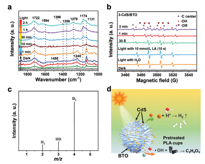
To reveal the photoreforming reaction pathway, in-situ studies were performed to explore the photoreforming process. The intermediates involved in plastic oxidation reaction were examined by using in-situ diffuse reflectance infrared Fourier transform spectroscopy (DRIFTS). Under dark condition, the pretreated PLA (LA) gradually absorbed on 3-CdS/BTO, resulting in the formation of different surface species in dark condition (Fig. 4a). For example, the out-of-plane bending of the carboxylate group (1722 cm–1), alcohol groups (1240 and 1132 cm–1), and methyl groups (1455 cm–1) can be observed [39]. Upon irradiation, the characteristic peaks associated with water and lactic acid vanish. In their place, new features emerge, including the stretching vibration of the carbonyl groups for pyruvate at 1594 cm–1, the CH3−C=O groups at 1174 cm–1, the COO− groups at 1735 cm–1, and the methyl groups at 1356 cm–1. The alterations observed in the DRIFTS suggest the utilization of LA and water, alongside the creation of PA [40]. In addition, the carbonate groups (1396 cm–1) are also observed due to the overoxidation of partial LA [41]. Besides, in-situ ESR measurements were performed in an argon (Ar) atmosphere to identify potential reactive oxygen species (ROS) and reaction intermediates. As shown in Fig. 4b, in the absence of LA, exposure to light triggers the formation of •OH (AN = AH = 14.9 G) [42,43]. This process occurs due to the oxidation of water by photogenerated holes. After adding LA, the signal of •OH disappear gradually; however, the signals of carbon-centered radicals (R• AN = 15.9 G, AH = 21.8 G) appear. As the reaction progresses, the signals of oxygen-centered radical (RO• AN = 14.51 G, AH = 10.71 G) also appear [44,45]. These signals indicate that when exposed to light, the activation of LA molecules begins with the cleavage of Cα−H and then α−OH, as well as the elimination of α-H. Simultaneously, the •OH signal decreases upon the addition of LA, likely due to the interaction between •OH and the removed α-H. Besides, in the photoreforming PLA process of BTO and CdS, BTO exhibits weak carbon-centered radicals, and no signal is detected over CdS, indicating that pristine BTO and CdS are difficult to activate Cα−H and α−OH of LA (Fig. S15 in Supporting information). In order to determine the source of hydrogen species within the H2 product, isotope-labeled deuterium water (D2O) and NaOD were substituted for H2O during the photoreforming PLA process. The mass spectrometry signals detected at m/z = 2, 3, and 4 are associated with H2, HD, and D2, respectively. This suggests that the released α-H from PLA swiftly reacts with OD to produce HDO, which then plays a role in the subsequent evolution of H2 (Fig. 4c).
Figure 4
Figure 4.
(a) Time-resolved in-situ DRIFTS of pretreated PLA on 3-CdS/BTO under dark and irradiated conditions. (b) In-situ EPR signals in the 3-CdS/BTO photoreforming system. (c) The mass spectra of gaseous products from photoreforming HER over 3-CdS/BTO using isotope-labeled D2O and LA as the reactants. (d) Proposed reaction pathway of photoreforming pretreated PLA.
According to the in-situ spectroscopy analyses, control experiments, and isotope-labeled experiments, the selective photoreforming of pretreated PLA on the 3-CdS/BTO S-scheme may proceed through several steps. The photogenerated electrons and holes were initially excited and accumulated in the CB of CdS and the VB of BTO. This process contributed to the generation of H2 by reducing the H+. Simultaneously, •OH radicals were produced as the holes in BTO reacted with water. Next, dehydrogenation can be initiated by •OH radicals attacking the α-H (Fig. 4d and Fig. S16 in Supporting information) or the α-OH groups, further contributing to the generation of R• and RO• radicals. Then, another •OH radical reacts with the R• or RO• radicals to form a C=O bond and an H2O molecule. In summary, the proposed mechanism for photoreforming can be outlined as follows:
As a result of 5 h of photoreforming on pretreated PLA, the procedure involved the involvement of roughly 1.26 mmol of electrons (e−) and 1.16 mmol of holes (h+) in the production of various redox products, as outlined in Table S4. The overall carrier balance in redox reactions is around 92%. This variation can be attributed to certain side products that were not identified during the 1H NMR and HPLC analyses.
In conclusion, S-scheme CdS/BTO photocatalysts were synthesized, interconnected through Bi–S bonds through in-situ growing CdS nanoparticles onto BTO nanoflowers using a facile hydrothermal method. XPS analyses and photoluminescence spectra confirmed that the Bi−S bond formed between the BTO and CdS interfaces serves as a rapid electron transfer channel, facilitating charge transfer at the interfaces and enhancing the built-in electric field in CdS/BTO S-scheme. This process involves the recombination of weak photoelectrons from the BTO CB with holes from the CdS VB. Simultaneously, it effectively separates and retains energetic photoelectrons in the CdS CB and holes in the BTO VB, allowing them to contribute to photoreforming. This facilitates the generation of •OH radicals, which further participate in the dehydrogenation reaction of LA. As a result, the yield rate of PA and H2 over CdS/BTO reach 1.7 and 3.16 mmol g–1 h–1, respectively, which are 2.8 and 22 times higher than those of BTO. This work not only presents a rational design of S-scheme photocatalysts through in-situ growing CdS on the surface of BTO photocatalysts; it also showcases the efficient utilization of photogenerated charge carriers by coupling H2 production with plastic oxidation.
Declaration of competing interest
The authors declare that they have no known competing financial interests or personal relationships that could have appeared to influence the work reported in this paper.
This work was supported by the National Natural Science Foundation of China (Nos. 52161145409, 21976116), SAFEA of China ("Belt and Road" Innovative Talent Exchange Foreign Expert Project No. 2023041004L), (High-end Foreign Expert Project No. G2023041021L), and Alexander-von-Humboldt Foundation of Germany (Group-Linkage Program).
Supplementary materials
Supplementary material associated with this article can be found, in the online version, at doi:10.1016/j.cclet.2025.111097.
Y. AlSalka, O. Al-Madanat, M. Curti, et al., ACS Appl. Energ. Mater. 3 (2020) 6678–6691. doi: 10.1021/acsaem.0c00826
[44]
Z. Huang, M. Shanmugam, Z. Liu, et al., J. Am. Chem. Soc. 144 (2022) 6532–6542. doi: 10.1021/jacs.2c01410
[45]
K. Zheng, Y. Wu, J. Zhu, et al., J. Am. Chem. Soc. 144 (2022) 12357–12366. doi: 10.1021/jacs.2c03866
Figure 1
Structure of as prepared heterojunctions. (a) Synthetic process of CdS/BTO. (b) SEM image, (c) TEM image, and (d) HRTEM images of 3-CdS/BTO composites. (e) EDS elemental mappings of Bi, Ti, O, S, and Cd elements in 3-CdS/BTO. (f) XRD patterns of CdS, BTO, and x-CdS/BTO.
Figure 2
Electron transfer between CdS and BTO within CdS/BTO composites. High-resolution XPS spectra of (a) Ti 2p, (b) O 1s, (c) Cd 3d and (d) Bi 4f for CdS, BTO, and 3-CdS/BTO. (e) UPS spectra of CdS and BTO. (f) DRS spectra of CdS, BTO, and x-CdS/BTO. In-situ XPS spectra of (g) Cd 3d and (h) Ti 2p for 3-CdS/BTO. (i) Proposed possible transfer route of photogenerated charge carriers.
Figure 3
Performance evaluation of photoreforming PLA. The H2 evolution rate during photoreforming PLA for (a) 5 h and (b) 50 h. (c) 1H NMR spectra of the pretreated PLA before and after photoreforming. (d) Organic acid yield from PLA for BTO, CdS, CdS/BTO, and CdS@BTO following 5 h of photoreforming. (e) The evolution rate of PA for 50 h and (f) control experiments with different scavengers over 3-CdS/BTO.
Figure 4
(a) Time-resolved in-situ DRIFTS of pretreated PLA on 3-CdS/BTO under dark and irradiated conditions. (b) In-situ EPR signals in the 3-CdS/BTO photoreforming system. (c) The mass spectra of gaseous products from photoreforming HER over 3-CdS/BTO using isotope-labeled D2O and LA as the reactants. (d) Proposed reaction pathway of photoreforming pretreated PLA.

 DownLoad:


 下载:
下载:


