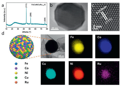
Figure 1.
(a) XRD pattern of FeCoNiCuRu1.5/C. (b, c) TEM images of FeCoNiCuRu1.5/C. (d) Model diagram of FeCoNiCuRu1.5/C nanoparticle and EDX elemental mapping of Fe, Co, Ni, Cu and Ru elements of FeCoNiCuRu1.5/C.
Multi-site synergistic relay electrocatalysis with high-entropy nanoalloys for effective nitrate reduction to ammonia
Anni Wu , Chengyi Hong , Hu Zheng , Wei Teng

Ammonia, as one of the world's most widely used chemicals, has extensive applications [1,2], serving as an important energy carrier in industry and as a fundamental raw material for agricultural fertilizers [3–5]. At present, the global annual production of ammonia is close to 200 million tons, the market value has exceeded US$70 billion, and the global demand continues to grow [6]. However, the traditional Haber-Bosch method used for ammonia production requires harsh conditions: high temperature and high pressure, and generates significant carbon emissions [7–10]. Consequently, it is essential to develop a sustainable method for ammonia synthesis that operates under mild conditions. Additionally, the release of industrial wastewater and the runoff from precipitation have disturbed the natural balance of nitrates, leading to the contamination of both surface water and groundwater resources [3,11,12]. Excessive nitrates in the environment can cause diseases such as "Methemoglobin disease", posing risks to public health [13]. From both energy and environmental perspectives, electrocatalytic reduction of nitrate to ammonia presents a promising approach. This technology not only mitigates nitrate pollution but also facilitates the conversion of these compounds into valuable ammonia, effectively transforming environmental waste into treasure [14,15].
Since the wide valence state of nitrogen is from −3 to +5, and the electrocatalytic reduction of nitrate to ammonia is a complex 9-proton and 8-electron transfer process, involving a variety of reaction pathways and intermediates [7,11,16,17]. The process is prone to challenges, including inadequate nitrate adsorption and complications in regulating product selectivity. The electrocatalytic process controls the catalytic reaction via the cathode interface material, necessitating the advancement of catalyst materials that exhibit both high activity and elevated ammonia selectivity. Presently, extensive research has been conducted on electrode materials aimed at facilitating the efficient reduction of nitrate and highly selective conversion of ammonia. A significant portion of this research has concentrated on monometallic and bimetallic alloys, particularly those that incorporate combinations of transition metals (such as Fe, Co, Ni, and Cu) alongside noble metals (including Pd, Ag, and Ru) [18,19]. However, the complex, multi-step nature of the reactions frequently impedes the capacity to efficiently regulate the activity at an individual active site, thereby complicating the simultaneous attainment of both high activity and selectivity [20].
High-entropy alloy, composed of five or more metallic elements, have garnered significant interest due to their unique properties, including the high entropy effect, hysteresis diffusion effect, lattice distortion effect, and synergistic effect [21]. The disordered and uniform distribution of metal atoms in the high-entropy alloy provides diverse active adsorption sites for efficient catalytic reaction [22,23]. The lattice distortion, arising from variations in atomic radius, optimizes charge redistribution within the high-entropy alloy. This process effectively reduces energy barriers associated with catalytic reactions, leading to a marked improvement in electrocatalytic activity [24]. Besides, the presence of multiple adjacent elements in high-entropy alloy provides unique conditions conducive to the generation of multiple active sites. Consequently, the manipulation of the composition and proportions of elements in high-entropy alloy can further alter the quantity and local structure of surface active sites. This optimization process enhances the synergistic catalytic effect, thereby improving the overall catalytic activity [25,26]. High-entropy alloys exhibit exceptional advantages in catalyst controllability, activity, and stability due to their distinctive physical and chemical properties [27]. Recent studies have proved that high-entropy alloys have extensive application potential in multi-step tandem reactions (such as CO2RR, EOR), highlighting their promising prospects in NO3RR [28]. For instance, a high-entropy FeCoNiAlTi alloy has been synthesized, exhibiting high activity in the electrocatalytic reduction of nitrate [29]. The extensive possibilities for elemental combinations in high-entropy alloys present numerous opportunities for further optimization and investigation of underlying mechanisms; however, current research in this domain is still relatively sparse.
In this work, high-entropy alloy nanoparticles supported on layered carbon were synthesized via high-temperature annealing of metal salts, utilizing dopamine as a carbon precursor. The alloy comprised Fe, Co, Ni, Cu, and Ru as metallic constituents with polydopamine acting as the carbon source. The investigation included variations in the Ru ratio to enhance catalytic performance. Notably, FeCoNiCuRu1.5/C achieved a nitrate conversion rate of 90.2% and an ammonia selectivity of 92.2% at −0.74 V (vs. RHE), outperforming the performance of FeCo/C, FeCoNi/C, and other medium and low entropy alloy catalysts by 1.5–2 times. Moreover, after 120 h of continuous operation (10 cycles), the nitrate conversion rate remains stable at about 90%. Through X-ray photoelectron spectroscopy (XPS), electron paramagnetic resonance (EPR), differential electrochemical mass spectrometry (DEMS), and other characterization techniques, combined with experiments under different conditions, elucidated the mechanism of multi-site synergistic relay catalysis of FeCoNiCuRu1.5/C in the electrocatalytic nitrate reduction to ammonia.
X-ray diffraction pattern (XRD, Fig. 1a) of the FeCoNiCuRu1.5/C catalyst shows three characteristic peaks at 43.7°, 50.9°, and 75.6°, corresponding to the (111), (200), and (220) crystal faces of the alloy crystal structure respectively [30,31]. This indicates that the high-entropy alloy is successfully synthesized and exhibits a typical face-centered cubic (fcc) structure. XRD tests were conducted on the synthesized FeCo/C, FeCoNi/C, FeCoNiCu/C, FeCoNiCuRu1.0/C, and FeCoNiCuRu2.0/C catalysts. In Fig. S1 (Supporting information), an increase in the number of metal constituents results in a shift of the diffraction peaks towards lower 2 theta angles, indicating that Fe, Co, Ni, Cu, and Ru form a solid solution during the heat treatment process [32]. The findings confirm that all synthesized materials successfully achieved alloy formation.
The microstructure of FeCoNiCuRu1.5/C was observed by scanning electron microscopy (SEM) and transmission electron microscopy (TEM). The TEM image presented in Fig. 1b distinctly illustrates that the spherical particles are enveloped in carbon layers, which were generated through the thermal treatment of polydopamine. In the carbon layer, the high-entropy alloy particles are uniformly distributed (Fig. S2 in Supporting information), with a diameter range of approximately 100–125 nm. Fig. 1c shows that the interplanar spacing of the exposed crystal face of an individual high-entropy alloy particle measures 0.219 nm, corresponding to the (111) crystal face of the alloy. SEM images (Fig. S3 in Supporting information) reveal a distinct spherical morphology of the material, illustrating the spherical morphology of particles supported on carbon. The energy-dispersive X-ray spectroscopy (EDX) elemental mapping analysis reveals the uniform distribution of Fe, Co, Ni, Cu, and Ru elements in the FeCoNiCuRu1.5/C (Fig. 1d), further confirming that Fe, Co, Ni, Cu, and Ru successfully formed high-entropy alloys. The EDX energy spectrum shows the mass ratio and atomic ratio of various metals present within an individual high-entropy alloy particle (Fig. S4 in Supporting information). ICP-OES was employed to determine the precise proportions of metallic elements present in the material (Table S1 in Supporting information). The results generally align with the EDX spectrum, except for a slightly lower Cu content and higher Ru content. The mass ratios of Fe, Co, and Ni correspond to the expected incorporation of the precursors. The mass ratios of Ru in FeCoNiCuRu1.0/C, FeCoNiCuRu1.5/C, and FeCoNiCuRu2.0/C are 1.90%, 2.84%, and 4.08%, respectively, consistent with the actual Ru mass ratios.
The surface chemical properties of FeCoNiCuRu1.5/C catalyst were analyzed by X-ray photoelectron spectroscopy (XPS, Fig. S5 in Supporting information). The XPS spectrum of Fe 2p in FeCoNiCuRu1.5/C shows the three main peaks at 707.74 eV (Fe 2p3/2, Fe⁰), 710.58 eV (Fe 2p3/2, Fe2+), and 713.39 eV (Fe 2p3/2, Fe3+), accompanied by two satellite peaks (Sat.). The Co 2p XPS spectrum displays a Co0 valence state at 778.94 eV (Co 2p3/2) and a Co2+ state at 779.97 eV (Co 2p3/2) as well as a Co3+ state at 782.23 eV (Co 2p3/2). The Ni 2p XPS spectrum shows two doublets, assigned to Ni0 at 854.60 eV (Ni 2p3/2), and Ni2+ at 855.92 eV (Ni 2p3/2) [33]. The Cu 2p XPS spectrum displays a doublet at 933.07 eV (Cu 2p3/2) assigned to Cu0 and a second doublet at 934.37 eV (Cu 2p3/2) assigned to Cu+. The Ru 3p spectra of FeCoNiCuRu1.5/C display two peaks at binding energies of 462.72 eV and 484.62 eV, being attributed to the Ru 3p3/2 and Ru 3p1/2 orbits of Ru [34].
In the electrocatalytic process, a typical H-cell served as the reactor. The counter electrode utilized was platinum foil, while a saturated calomel electrode functioned as the reference electrode, operating at a potential of −0.74 V (vs. RHE). The electrocatalytic performances of various alloy catalysts, including FeCo/C, FeCoNi/C, FeCoNiCu/C, and a series with incremental additions of Ru (FeCoNiCuRu1.0/C, FeCoNiCuRu1.5/C, and FeCoNiCuRu2.0/C) in the nitrate reduction to ammonia were tested (Fig. S6 in Supporting information). The introduction of ruthenium significantly enhanced ammonia selectivity (Fig. 2a), suggesting that Ru plays a crucial role in modulating the selective reduction of nitrate to ammonia. Among the catalysts assessed, FeCoNiCuRu1.5/C exhibited the highest nitrate conversion rate of 90.2% and an ammonia selectivity of 92.2%, which is more than double the conversion rate observed with FeCoNiCu/C of 41.9% in the absence of Ru. Besides, the experimental findings indicate a significant variation in performance of catalysts with different Ru content is obviously different. Thermodynamically, the conversion of NO3− to *NO3 on the Ru surface is favorable. However, the strong adsorption of *NO3 on the Ru surface presents challenges in the subsequent reduction of *NO3 to *NO2 [35,36]. Therefore, when the Ru content in the alloy surpasses a specific threshold, the reduction transformation to *NO2 is impeded, significantly diminishing the electrocatalytic reduction efficiency of nitrate [37]. On the other hand, the excess of Ru may augment the activity of the competing hydrogen evolution reaction (HER), resulting in a reduction in the conversion of nitrate [38]. Furthermore, the temporal variations in the concentrations of nitrate, nitrite, and ammonium ions during the electrocatalytic process using FeCoNiCuRu1.5/C are depicted in Fig. 2b. The selectivity of ammonia remains above 90%, and the conversion rate of nitrate rises with time, and ultimately reaching 90.2%. Notably, no nitrite was detected during the reaction, and the predominant product was ammonia, with only trace amounts of nitrogen produced, which may have slightly diminished ammonia production due to anodic oxidation. Electrocatalytic reduction experiments involving nitrate were performed under open circuit conditions, utilizing pure carbon paper as the working electrode (Fig. S7 in Supporting information). The findings indicated a low reduction efficiency, suggesting that the catalyst exhibits considerable activity and is crucial in facilitating the reduction of nitrate. Given its superior performance in nitrate reduction reactions (NO3RR), the FeCoNiCuRu1.5/C electrocatalyst was selected for further investigations.
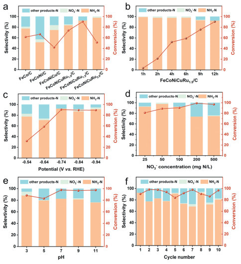
The NO3- conversion rate of the FeCoNiCuRu1.5/C catalyst gradually increases from −0.54 V to −0.74 V (vs. RHE), ultimately reaching a peak and stabilizing within the range of −0.74 to −0.94 V (vs. RHE) (Fig. 2c). This indicates that an optimal potential of NO3RR is −0.74 V (vs. RHE) is essential for attaining the high electrocatalytic activity in nitrate reduction, indicating that the FeCoNiCuRu1.5/C catalyst requires a specific applied potential to enhance its efficacy in this process. Moreover, an increase in the initial nitrate concentration is associated with a corresponding rise in the nitrate conversion rate (Fig. 2d). This phenomenon may be attributed to the constraints on mass transfer and the accumulation of nitrate at the catalyst surface observed at lower initial nitrate concentrations. Conversely, at elevated initial nitrate concentrations, the conditions become more conducive for nitrate accumulation at the interface, thereby improving its reduction efficiency. When the initial nitrate concentration rises to > 200, the selectivity of N2 increases slightly. This suggests that excessive nitrate may lead to incomplete reduction of NO3-, and thus conversion to intermediate products such as N2 [17,39]. NO3- conversion and NH3 selectivity are relatively stable across a broad pH range (3–11), with conversion rates surpassing 97% within the pH range of 7–11, indicating the effective performance of catalyst under diverse acidic and alkaline conditions (Fig. 2e). The remarkable stability observed in high-entropy alloys can be ascribed to their distinctive slow diffusion characteristics, coupled with the protective role of carbon layers. This combination enables these materials to sustain their activity in environments where water quality fluctuates, influenced by variables such as pH [27]. At a pH 3, the selectivity for ammonia is higher than at other pH levels, which can be ascribed to the increased concentration of H+ and the resultant production of active hydrogen and nitrogenous intermediates. Conversely, at pH 3 and 5, the nitrate conversion rate is slightly lower than that observed in neutral and alkaline electrolytes, potentially due to the competitive reaction associated with hydrogen evolution [40].
The stability of electrocatalytic activity is a critical prerequisite for practical applications. Over a duration of 120 h, encompassing 10 cycles of prolonged electrocatalysis, the nitrate conversion rate consistently remained at approximately 90% (Fig. 2f). FeCoNiCuRu1.5/C displays excellent stability and ammonia selectivity in NO3RR. Leaching tests conducted using ICP-OES were employed to assess the concentrations of Fe, Co, Ni, Cu, and Ru in the electrolyte following the electrocatalysis process (Table S2 in Supporting information). The results reveal negligible metal ion release into the electrolyte with concentrations below the detection limit of 0.01 mg/L. It is clarified that the material possesses significant stability and is not expected to contribute to secondary pollution.
To assess the superior electrocatalytic properties of FeCoNiCuRu1.5/C, a series of electrochemical characterizations were conducted. The electrochemical active surface area (ECSA) of FeCo/C, FeCoNi/C, FeCoNiCu/C, FeCoNiCuRu1.0/C, FeCoNiCuRu1.5/C, and FeCoNiCuRu2.0/C were estimated using electrochemical double layer capacitance (CDL). As shown in Fig. S8 (Supporting information), the cyclic voltammetry curves of the six groups of materials were measured at different scanning rates in the non-Faraday current region, and the CDL of the high-entropy alloy was generally superior to that of the low-entropy alloy. As depicted in Fig. 3a, the calculated CDL (24.19 mF/cm2) for FeCoNiCuRu1.5/C exceeds that of FeCoNiCuRu1.0/C computed CDL (12.84 mF/cm2) and FeCoNiCuRu2.0/C computed CDL (11.59 mF/cm2). The results indicate that FeCoNiCuRu1.5/C maintains a high density of catalytically active sites while Ru incorporation enhances the hydrogenation of nitrogenous intermediates, thereby improving both nitrate conversion and ammonia selectivity.
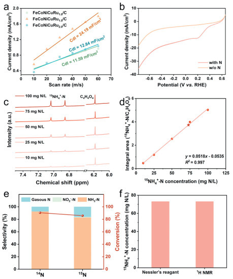
Linear sweep voltammetry test (Fig. S9 in Supporting information) and cyclic voltammetry test (Fig. S10 in Supporting information) were performed on the catalysts. The results display that all six groups of catalyst materials show distinct redox peaks, which proves that the catalysts have electrochemical activity of nitrate reduction. Notably, FeCoNiCuRu1.5/C electrocatalyst demonstrates the highest current density and the lowest overpotential. As depicted in Fig. 3b, the cathodic current density of FeCoNiCuRu1.5/C markedly increases in the presence of NO3-, suggesting a strong responsiveness to NO3- and an excellent potential for efficient conversion of NO3-. To quantitatively establish that ammonia was derived from nitrates in the electrolyte, 1H NMR analysis (Fig. 3c) and 15N isotope labeling experiments (Fig. 3e) were performed [41,42]. The results demonstrated a linear relationship (Fig. 3d), and the measured nitrate conversion and product selectivity were consistent with findings obtained via UV–visible spectrophotometry (Fig. 3f). Consequently, when comparing the NO3RR performance of FeCoNiCuRu1.5/C with reported catalysts (Table S3 in Supporting information), exhibits superior higher nitrate conversion rate and ammonia selectivity, which holds considerable importance for the efficient electrocatalytic reduction of nitrate to ammonia in wastewater treatment applications (Fig. S11 in Supporting information).
Electrocatalytic nitrate reduction to ammonia can occur via two distinct pathways: One is the indirect active hydrogen-mediated reduction at the active site, and the other is the direct electron-mediated reduction at the cathode electrons [8,43–46]. To elucidate the pathway of electrocatalytic nitrate reduction to ammonia over FeCoNiCuRu1.5/C, an electron spin resonance (ESR) experiment was performed (Fig. 4a) employing 5, 5-dimethylpyrrolin-1-oxide (DMPO) as a trapping agent to detect the presence of *H in electrocatalysis. After 30 min of electrocatalysis at a potential of −0.74 V (vs. RHE), the active hydrogen *H signal was observed in the electrolyte without nitrate, whereas no peak of active hydrogen was detected in the electrolyte containing nitrate. This observation reflects that the nitrate reduction process captures the active hydrogen generated by the FeCoNiCuRu1.5/C promotion. Additionally, intermediate gaseous products during the electrocatalysis reaction were further identified using in situ differential electrochemical mass spectrometry (DEMS). The results show that NO2, NO, N, NH, NH2, and NH3 signals were detected in six cycles with a duration of 500 s under the applied potential of 0.74 V (vs. RHE) (Fig. 4b), while N2 was scarcely detected, thereby confirming the selective conversion of nitrate to ammonia facilitated by the FeCoNiCuRu1.5/C catalyst. The detection of NH2OH was minimal, suggesting that the *NO intermediate produced during the reduction reaction is more likely to yield *N for the subsequent step in ammonia synthesis [47]. Consequently, a preliminary hypothesis regarding the reaction pathway has been formulated: *NO3, *NO2, *NO, *N, *NH, *NH2, and *NH3 [11,17,34].
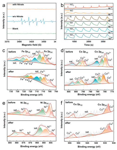
The alterations in the catalyst surface prior to and following the reaction were examined through the application of X-ray photoelectron spectroscopy (XPS). The XPS spectrum of Fe 2p (Fig. 4c) exhibited a notable chemical shift in the zero-valence Fe, suggesting modifications in its electronic state. Likewise, the spectra for Co 2p (Fig. 4d) and Ni 2p (Fig. 4e) demonstrated an increase in the chemical shift associated with the oxidation state subsequent to the catalytic reaction. These shifts are likely attributed to the propensity of Co and Ni to interact with more electronegative groups or ions during the reaction process [48–51]. Furthermore, the XPS spectrum reveals that the binding energies associated with the metallic states of Fe, Co, Ni, and Cu have experienced differing extents of positive shifts (Fig. 4f). This indicates that there is a charge redistribution on the surface of the high-entropy alloy. It leads to alterations to in the electronic structure and density and promotes the electrocatalytic activity of FeCoNiCuRu1.5/C. Additionally, the observed increase in peak intensity of hydroxide in the O 1s XPS spectrum (Fig. S12 in Supporting information) following the reaction likely results from the transition metals capturing environmental hydroxide, facilitating redox interactions during the NO3RR process.
Based on the above experimental data and characterization results, the mechanism of highly selective conversion of nitrate to ammonia on the surface of FeCoNiCuRu1.5/C material was deduced. The reduction mechanism is mainly attributed to the synergistic relay catalytic transformation between the break of the N—O bond at the transition metal site and the hydrogenation of ammonia at the Ru site. A comparative analysis of the fitted X-ray photoelectron spectroscopy (XPS) spectra, conducted before and after the reaction, reveals that the oxidation states of Co and Ni have positive shifts, whereas the oxidation states of Fe show negative shifts. This observation indicates that with the types of metal atoms increase, electron rearrangement occurs on the surface of the alloy catalyst, thereby enhancing the types of active sites and decreasing the binding energy between NO3- and metal atoms. The incorporation of Ru into the FeCoNiCuRu1.5/C composite results in the exposure of Ru active sites. These sites facilitate the generation and adsorption of active hydrogen *H [37,52,53]. The active hydrogen subsequently interacts with the intermediates produced following the cleavage of the N—O bond on the catalyst surface, thereby enabling the efficient conversion of these intermediates into ammonia. Meanwhile, the coordination of transition metal sites with the Ru site facilitates the hydrogenation process in ammonia synthesis by enhancing the migration of the *H intermediate to the neighboring *N adsorption site [54].
To enhance the validation of the electrocatalytic reduction mechanism of nitrate on FeCoNiCuRu1.5/C, we established models for FeCoNiCuRu1.5/C, FeCo/C, and FeCoNiCu/C, respectively (Fig. S13 in Supporting information). And theoretical calculations were carried out based on density functional theory (DFT). Firstly, we conducted a comparative analysis of the changes observed in ordinary binary FeCo and those observed in the high-entropy alloy FeCoNiCuRu1.5/C following the adsorption of NO3- (Fig. 5a). The charge density difference results indicate a more pronounced alternation of charge on the surface of FeCoNiCuRu1.5/C, suggesting that multiple sites can facilitate synergistically the transfer of charge to NO3- adsorbed on the surface when the metal element species in the catalyst is increased. Similarly, the adsorption energy of FeCoNiCuRu1.5/C for NO3- was −0.32 eV (Table S4 in Supporting information), which was more negative than that of FeCo (−0.17 eV) (Table S5 in Supporting information), indicating that the optimized charge distribution among different atoms facilitated the adsorption of nitrate at the interface (Fig. 5b). Besides, the HER was calculated following the addition of Ru elements (Fig. 5c). The results demonstrate that H2O on FeCoNiCu can dissociate spontaneously to *H, with the step from H2O to *H on the surface of FeCoNiCuRu1.5/C exhibiting a more negative free energy and the generated *H being more stable. The energy required to generate H₂ from *H is 0.53 eV for FeCoNiCuRu1.5/C (Table S6 in Supporting information), which is larger than the 0.41 eV required by FeCoNiCu (Table S7 in Supporting information). This proves that FeCoNiCuRu1.5/C can inhibit hydrogen evolution reaction more effectively and increase the efficiency of nitrate reduction.
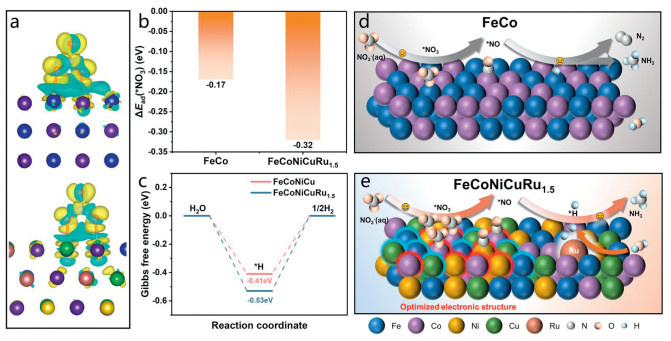
Therefore, in comparison to FeCo/C, FeCoNi/C, FeCoNiCu/C, and other low entropy alloy materials (Fig. 5d), NO3- is more easily adsorbed to the catalyst surface amplifying the difference in charge density, reducing the binding energy between NO3- and metal atoms, and thus promoting NO3- adsorption to the catalyst surface (Fig. 5e) [29,37,54]. Furthermore, following high-temperature annealing, the conductive carbon layer obtained from dopamine functions as a carrier for the high-entropy alloy. This layer facilitates the dispersion of alloy particles, mitigates their agglomeration, and improves electrical conductivity.
In conclusion, the high-entropy alloy catalyst FeCoNiCuRu1.5/C was synthesized for the NO3RR process. FeCoNiCuRu1.5/C demonstrated remarkable activity in electrocatalytic nitrate reduction, achieving a nitrate conversion rate of 90.5% and an ammonia selectivity of 92.2% at a potential of −0.74 V (vs. RHE) potential. This performance substantially exceeds that of low-entropy nanoalloys like FeCo/C, with improvements ranging from 1.5 to 2 times. FeCoNiCuRu1.5/C maintains a nitrate conversion rate of about 90.0% after 120 h of continuous operation (10 cycles), indicating its high stability. This excellent performance is attributed to the efficient regulation of the complex multi-step reaction of nitrate by multi-site synergistic relay electrocatalysis in high-entropy alloys. The differences in atomic radius and electronegativity of Fe, Co, Ni, Cu, and Ru lead to a redistribution of the surface charge density of the catalyst. This redistribution reduces the adsorption energy of NO3- at the interface of the material, thus accelerating the reduction process of nitrate. Subsequently, the Ru site promotes the capture of *H by intermediate species for selective production of ammonia. The structure of the high-entropy alloy dispersed in the graphitized carbon layers also enhances the stability of the catalyst. This research paves the way for the advancement of catalysts that leverage multi-site collaborative relay catalysis, thereby enhancing performance in complex chemical transformations.
The authors declare that they have no known competing financial interests or personal relationships that could have appeared to influence the work reported in this paper.
Anni Wu: Writing – original draft, Validation, Investigation, Formal analysis, Data curation. Chengyi Hong: Validation, Investigation, Formal analysis, Data curation. Hu Zheng: Supervision, Resources, Funding acquisition. Wei Teng: Writing – review & editing, Supervision, Resources, Project administration, Methodology, Funding acquisition, Conceptualization.
This work was financially supported by the Shanghai Science and Technology Plan Project (No. 23ZR1467000), Basic Research Project of Tongji University (No. 22120240354), State Key Laboratory of Treatments and Recycling for Organic Effluents by Adsorption in Petroleum, Chemical Industry (No. SDHY2206), National Natural Science Foundation of China (No. 21976134) and the Fundamental Research Funds for the Central Universities.
Supplementary material associated with this article can be found, in the online version, at doi:
V. Smil, Glob. Biogeochem. Cycle 13 (1999) 647–662. doi: 10.1029/1999GB900015
J.G. Chen, R.M. Crooks, L.C. Seefeldt, et al., Science (1979) 360 (2018) eaar6611.
J.D. Stoner, M.R. Burkart, Water Sci. Technol. 56 (2007) 59–69.
C. Smith, L. Torrente-Murciano, Joule 8 (2024) 157–174. doi: 10.1016/j.joule.2023.12.002
C. Smith, A.K. Hill, L. Torrente-Murciano, Energy Environ. Sci. 13 (2020) 331–344. doi: 10.1039/c9ee02873k
J. Lim, C.A. Fernández, S.W. Lee, et al., ACS Energy Lett. 6 (2021) 3676–3685. doi: 10.1021/acsenergylett.1c01614
D. Yao, C. Tang, P. Wang, et al., Chem. Eng. Sci. 257 (2022) 117735. doi: 10.1016/j.ces.2022.117735
C. Guo, J. Ran, A. Vasileff, et al., Energy Environ. Sci. 11 (2018) 45–56. doi: 10.1039/c7ee02220d
Y. Liu, M. Cheng, Z. He, et al., Angew. Chem. Int. Ed. 58 (2018) 731–735. doi: 10.1002/anie.201808177
G. Soloveichik, Nat. Catal. 2 (2019) 377–380. doi: 10.1038/s41929-019-0280-0
Z. Zhang, N. Zhang, J. Zhang, et al., Chem. Eng. J. 483 (2024) 148952. doi: 10.1016/j.cej.2024.148952
X. Chen, T. Zhang, M. Kan, et al., Environ. Sci. Technol. 54 (2020) 13344–13353. doi: 10.1021/acs.est.0c05631
A. Menció, J. Mas-Pla, N. Otero, et al., Sci. Total Environ. 539 (2016) 241–251. doi: 10.1016/j.scitotenv.2015.08.151
W. Kang, L. Yan, J. Tang, et al., Appl. Catal. B: Environ. 329 (2023) 122553. doi: 10.1016/j.apcatb.2023.122553
Y. Zeng, C. Priest, G. Wang, et al., Small. Methods 4 (2020) 2000672. doi: 10.1002/smtd.202000672
D. Chen, S. Zhang, D. Yin, et al., Adv. Energy Mater. 13 (2022) 2203201.
Z. Wu, Y. Song, Y. Liu, et al., Chem. Catal. 3 (2023) 100786.
A.S. Fajardo, P. Westerhoff, C.M. Sanchez-Sanchez, et al., Appl. Catal. B: Environ. 281 (2021) 119465. doi: 10.1016/j.apcatb.2020.119465
S. Garcia-Segura, M. Lanzarini-Lopes, K. Hristovski, et al., Appl. Catal. B: Environ. 236 (2018) 546–568. doi: 10.1016/j.apcatb.2018.05.041
Y. Zhou, L. Zhang, M. Wang, et al., ACS Catal. 14 (2024) 7907–7916. doi: 10.1021/acscatal.4c00879
J.W. Yeh, S.K. Chen, S.J. Lin, et al., Adv. Eng. Mater. 6 (2004) 299–303. doi: 10.1002/adem.200300567
H. Li, J. Lai, Z. Li, et al., Adv. Funct. Mater. 31 (2021) 2106715. doi: 10.1002/adfm.202106715
Y. Yao, Q. Dong, A. Brozena, et al., Science (1979) 376 (2022) eabn3103.
Z. Jia, T. Yang, L. Sun, et al., Adv. Mater. 32 (2020) 2000385. doi: 10.1002/adma.202000385
J.T. Ren, L. Chen, H.Y. Wang, et al., Chem. Soc. Rev. 52 (2023) 8319–8373. doi: 10.1039/d3cs00557g
Y. Zhang, D. Wang, S. Wang, Small. 18 (2021) 2104339.
L. Fan, Y. Ji, G. Wang, et al., J. Am. Chem. Soc. 144 (2022) 7224–7235. doi: 10.1021/jacs.1c13740
E.P. George, D. Raabe, R.O. Ritchie, Nat. Rev. Mater. 4 (2019) 515–534. doi: 10.1038/s41578-019-0121-4
R. Zhang, Y. Zhang, B. Xiao, et al., Angew. Chem. Int. Ed. (2024) e202407589.
A. Sivanantham, H. Lee, S.W. Hwang, et al., J. Mater. Chem. A 9 (2021) 16841–16851. doi: 10.1039/d1ta02621f
Q. Zou, H. Ren, Y. Li, et al., J. Mater. Sci. Technol. 190 (2024) 117–126. doi: 10.1016/j.jmst.2023.11.058
W.H. Liu, Y. Tong, S.W. Chen, et al., Matter. 2 (2020) 751–763. doi: 10.1016/j.matt.2019.12.023
Z. Zhang, Y. Liu, X. Su, et al., Nano Res. 16 (2023) 6632–6641. doi: 10.1007/s12274-023-5402-y
J. Su, K. Shi, B. Liu, et al., Adv. Funct. Mater. 34 (2024) 2401194. doi: 10.1002/adfm.202401194
F.Y. Chen, Z.Y. Wu, S. Gupta, et al., Nat. Nanotechnol. 17 (2022) 759–767. doi: 10.1038/s41565-022-01121-4
J. Li, G. Zhan, J. Yang, et al., J. Am. Chem. Soc. 142 (2020) 7036–7046. doi: 10.1021/jacs.0c00418
W. Gao, K. Xie, J. Xie, et al., Adv. Mater. 35 (2023) 2202952. doi: 10.1002/adma.202202952
C. Cai, K. Liu, Y. Zhu, et al., Angew. Chem. Int. Ed. 61 (2021) e202113664.
Q. Song, M. Li, X. Hou, et al., Appl. Catal. B: Environ. 317 (2022) 121721. doi: 10.1016/j.apcatb.2022.121721
Y. Xue, Q. Yu, Q. Ma, et al., Environ. Sci. Technol. 56 (2022) 14797–14807. doi: 10.1021/acs.est.2c04456
R. Zhang, Y. Guo, S. Zhang, et al., Adv. Energy Mater. 12 (2022) 2103872. doi: 10.1002/aenm.202103872
Y. Liu, J. Ma, S. Huang, et al., Nano Energy 117 (2023) 108840. doi: 10.1016/j.nanoen.2023.108840
Y. Wang, C. Wang, M. Li, et al., Chem. Soc. Rev. 50 (2021) 6720–6733. doi: 10.1039/d1cs00116g
H. Xu, Y. Ma, J. Chen, et al., Chem. Soc. Rev. 51 (2022) 2710–2758. doi: 10.1039/d1cs00857a
H. Zhang, K. Fang, J. Yang, et al., Coord. Chem. Rev. 506 (2024) 215723. doi: 10.1016/j.ccr.2024.215723
J. Theerthagiri, J. Park, H.T. Das, et al., Environ. Chem. Lett. 20 (2022) 2929–2949. doi: 10.1007/s10311-022-01469-y
Y. Zhou, L. Zhang, Z. Zhu, et al., Angew. Chem. Int. Ed. 63 (2024) e202319029. doi: 10.1002/anie.202319029
M.C. Biesinger, B.P. Payne, A.P. Grosvenor, et al., Appl. Surf. Sci. 257 (2011) 2717–2730. doi: 10.1016/j.apsusc.2010.10.051
Y. Liu, X. Zhong, M. Liu, et al., Appl. Catal. B: Environ. Energy 355 (2024) 124205. doi: 10.1016/j.apcatb.2024.124205
W. Zheng, L. Zhu, Z. Yan, et al., Environ. Sci. Technol. 55 (2021) 13231–13243. doi: 10.1021/acs.est.1c02278
Y. Yu, C. Wang, Y. Yu, et al., Sci. China-Chem. 63 (2020) 1469–1476. doi: 10.1007/s11426-020-9795-x
S. Han, H. Li, T. Li, et al., Nat. Catal. 6 (2023) 402–414. doi: 10.1038/s41929-023-00951-2
H. Cao, B. Liang, S. Ye, et al., Chem. Eng. J. 490 (2024) 151883. doi: 10.1016/j.cej.2024.151883
W. Zhu, F. Yao, Q. Wu, et al., Energy Environ. Sci. 16 (2023) 2483–2493. doi: 10.1039/d3ee00371j

Figure 1 (a) XRD pattern of FeCoNiCuRu1.5/C. (b, c) TEM images of FeCoNiCuRu1.5/C. (d) Model diagram of FeCoNiCuRu1.5/C nanoparticle and EDX elemental mapping of Fe, Co, Ni, Cu and Ru elements of FeCoNiCuRu1.5/C.

Figure 2 (a) Nitrate conversion rate and product selectivity of different electrocatalyst materials under −0.74 V (vs. RHE) for 12 h. (b) The change of nitrate, nitrite, and ammonium ion concentrations with time during the electrocatalysis of FeCoNiCuRu1.5/C. (c) The electrocatalytic nitrate reduction performance of FeCoNiCuRu1.5/C under different pH. (d) The electrocatalytic nitrate reduction performance of FeCoNiCuRu1.5/C at different applied potential. (e) The electrocatalytic nitrate reduction performance of FeCoNiCuRu1.5/C at different initial nitrate concentration. (f) Nitrate conversion and selectivity over FeCoNiCuRu1.5/C in 10 cycles.

Figure 3 (a) CDL values of high-entropy nanoalloy materials with different Ru content. (b) LSV curves of FeCoNiCuRu1.5/C electrocatalyst in the presence and absence of nitrate. (c) The 1H NMR spectra using series of 15NH4-N solution with known concentration as standards in 0.1 mol/L Na2SO4. (d) Calibration curves of 15NH4-N. (e) NO3RR performance using 14N and 15N as N source over FeCoNiCuRu1.5/C respectively, respectively. (f) Comparison of different methods to detect ammonia from electroreduction of nitrate.

Figure 4 (a) Electron spin resonance (ESR) test of FeCoNiCuRu1.5/C electrocatalyst at −0.74 V (vs. RHE). (b) Differential electrochemical mass spectrometry (DEMS) of FeCoNiCuRu1.5/C electrocatalyst. (c-f) X-ray photoelectron spectroscopy (XPS) spectra of FeCoNiCuRu1.5/C before and after the reaction.

Figure 5 (a) Charge density difference profiles for NO3− adsorption on FeCo and FeCoNiCuRu1.5. (b) The absorption energy of NO3- on FeCoNiCuRu1.5 and FeCo surface. (c) Gibbs energy profile of FeCoNiCuRu1.5 and FeCoNiCu for HER. (d, e) The process of nitrate reduction to ammonia on the surface of FeCo and FeCoNiCuRu1.5, respectively.

 扫一扫看文章

扫一扫关注我们
 DownLoad:
 下载:
下载: