Citation:
Xifeng Lu, Pei Su. Design and application of metal-organic frameworks derivatives as 3-electron ORR electrocatalysts for •OH generation in wastewater treatment: A review[J]. Chinese Chemical Letters,
2025, 36(11): 110909.
doi:
10.1016/j.cclet.2025.110909
Design and application of metal-organic frameworks derivatives as 3-electron ORR electrocatalysts for •OH generation in wastewater treatment: A review
English
Design and application of metal-organic frameworks derivatives as 3-electron ORR electrocatalysts for •OH generation in wastewater treatment: A review
Hebei Key Laboratory of Applied Chemistry and Hebei Key Laboratory of Heavy Metal Deep−Remediation in Water and Resource Reuse, School of Environmental and Chemical Engineering, Yanshan University, Qinhuangdao 066004, China
Received Date:
16 October 2024 Accepted Date:
03 February 2025 Revised Date:
20 November 2024 Available Online:
15 November 2025
Abstract:
Derivatives of metal−organic frameworks (MOFs) are a promising bifunctional electrocatalysts in electrochemical advanced oxidation processes (EAOPs). These metal/carbon materials overcome the limitations of individual components by creating synergistic effects. EAOPs is primarily constrained by the generation and activation of H2O2. This article examines the regulatory strategies employed in MOFs derivatives to enhance the production of H2O2via 2e− pathways and its activation to •OH, focusing on preparation techniques, structures, and compositions. The design of these derivatives involves methods such as metal dispersion on the surface of nanocarbons, embedding in carbon shells, and atomic dispersion of metals anchored in porous carbon. MOFs derivatives promote •OH production and enhance wastewater purification through mechanisms such as boosting the Fe(Ⅱ)/Fe(Ⅲ) cycle, facilitating direct 3e− reactions of O2, and interacting of O2•−. Moreover, the performance and durability of MOFs derivatives in wastewater treatment, particularly in influencing •OH generation within EAOPs, were investigated. This review addresses current challenges and future prospects, offering valuable insights for the development of MOFs derivatives as 3e− ORR electrocatalysts and the advancement of sustainable water treatment technologies.
In the era of modern industrialization and rapid economic growth, the demand for water resources has surpassed the available supply required for human agriculture and manufacturing activities [1,2]. This situation is aggravated by the emerging contaminants (EC) that contribute to the deterioration of the global water system and widen the gap between supply and demand [3]. EC such as persistent organic pollutants, endocrine disrupting compounds, antibiotics, micro plastics, and other contaminants possess toxic, persistent and non−biodegradable characteristics, posing serious threats to ecological environment and human health [4,5]. Although the concentrations of these pollutants range from ng/L to µg/L, their prolonged existence can lead to bacterial resistance in the environment [6,7]. Therefore, there is a critical need to advance technologies capable of effectively eliminating these harmful compounds, with electrochemical advanced oxidation processes (EAOPs) is a promising solution to purify organic wastewater because of rapid purification performance, versatility, simplicity, and environmental friendliness [8,9].
According to the number of transferred electrons, oxygen reduction reaction (ORR) can be divided into two categories: 2e− reactions, where O2 is reduced to H2O2 (Eq. 1), and 4e− reactions, where it is reduced to H2O (Eq. 2). EAOPs leverage O2 as a reactant to enable a 2e− ORR, resulting in the in−situ production of reactive oxygen species (ROS) like •OH (Eq. 3), O2•−, and 1O2 [10,11]. The exceptional oxidation potential of •OH (oxidation potential of 2.80 V) positions it as a favorable candidate for effectively treating organic pollutants due to its potent oxidizing properties [12]. Challenges within the EAOPs process, such as low selectivity and active electrocatalysts for 2e− ORR, inefficient H2O2 activation, •OH quenching by transition metal atoms and H2O2, and sluggish iron cycling kinetics hinder its efficiency in removing organic pollutants [13-15]. To address these limitations, the idea of developing electrocatalysts for the 3e− ORR process is proposed (Eq. 4). This involves creating an electrocatalyst that enhances 2e− ORR, activates H2O2 into •OH through 1e− ORR, and subsequently enhances pollutant degradation efficiency and electrocatalyst stability. By focusing on promoting selective H2O2 intermediate production and fine−tuning the adsorption and activation energies of H2O2 on the electrocatalyst surface, the scientific barrier of the 3e− ORR can be overcome, resulting in the accelerated 3e− electrocatalytic activation of O2 to produce •OH.
O2 + 2H+ + 2e− → H2O2
(1)
O2 + 4H+ + 4e− → 2H2O
(2)
H2O2 + H+ + e− → •OH + H2O
(3)
O2 + 3H+ + 3e− → •OH + H2O
(4)
Metal organic frameworks (MOFs) are innovative crystal hybrids formed through coordination bonds between metal ions (or clusters) and organic ligands [16-18]. These frameworks are extensively utilized in fields such as gas storage, separation, catalysis, and sensing because of high open pore, porosity and specific surface area, and numerous active sites [19-21]. A promising solution lies in utilizing MOFs as precursors to prepare metal/carbon hybrids that show improved firmness and conductivity than that of original MOFs [22]. These derivatives retain the high surface area, customized porosity, and predetermined functions of original MOFs, making them highly favorable for environmental remediation purposes [23-26]. In recent years, there has been significant researches exploring the application of MOFs derivatives in wastewater treatment [27-29]. This research is focused on understanding how the morphology and structure of MOFs influences catalytic performance and the properties of active sites. While MOFs derivatives have garnered attention for their role in 2e− and 4e− ORR in fuel cells [30-32], there has been a lack of focus on the mechanism of 3e− on the surface of electrocatalysts in EAOPs. Addressing this gap is crucial because selecting and understanding different ORR pathways are essential for designing catalysts in EAOPs. These ORR pathways directly influence the production and efficiency of •OH. Therefore, this article aims to review the mechanisms for devising and deriving active sites in MOFs for 3e−, as well as strategies to enhance •OH generation performance.
This review offers an overall overview of recent studies in utilizing MOFs derivatives as 3e− ORR electrocatalysts in EAOPs, focusing on the preparation strategies, functional mechanisms, and performance studies of MOFs derivatives. Initially, the discussion will center on the composition, structure, and design strategies of active sites for MOFs derivatives aimed at achieving the 2e− production of H2O2 and 1e− activation of H2O2 to produce •OH. Next, the performance evaluation and potential applications of MOFs derivatives in purifying wastewater will be presented, emphasizing their influence on the purification of wastewater by •OH. Lastly, the challenges and future prospects of utilizing MOFs derivatives as 3e− ORR electrocatalysts in EAOPs will be addressed.
2.
MOFs−derived electrocatalysts for 2e− ORR
2.1
MOFs derived porous carbon
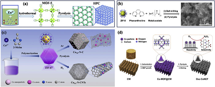
Porous carbon, characterized by its firmness, conduction, porosity, and adjustable chemistry of surface, as well as its low cost, has attracted growing interest as an electrocatalyst for the ORR [33,34]. The generation of H2O2via the 2e− pathway in the 3e− ORR serves as the initial determining factor for the yield of •OH. Carbonization of MOFs represents a key method for producing porous carbon with unique properties, such as a high concentration of micropores, mesopores and macropores within a graded porous structure [35]. MOF-5, a coordination compound consisting of terephthalic acid (H2BDC) as the bridging ligand and the [Zn4O]6+ metal cluster as the central unit, stands out as a promising precursor for obtaining such porous carbon materials. The synthesis of MOF-5 was achieved through hydrothermal methods at 100 ℃ for 24 h. Subsequently, the compound underwent carbonization at 1100 ℃ for 5 h in an H2 atmosphere, resulting in the production of hierarchically porous carbon (HPC) with notable surface area of 2130 m2/g (Fig. 1a) [36]. During the carbonization process, the controlled evaporation of Zn, which takes place above its boiling point of 908 ℃, is crucial for the formation of pure porous carbon with defect sites. This process, when conducted in a H2 atmosphere, facilitates the conversion of sp2-C into sp3-C [37]. These transformations were found to enhance the accumulation of *HO2, thus enabling the achievement of high production rates of H2O2, ranging from 395.7 mmol h−1 g−1 to 110.2 mmol h−1 g−1 across a pH spectrum of 1 to 7, at a potential of −0.5 V (vs. SCE).
Figure 1
Figure 1.
Schematic diagram of (a) HPC preparation, (b) the M−N−C catalysts (M = Co, Ni, Fe, Cu, and Mn), and SEM image of the Co−N−C catalyst, (c) CoSA−N−CNTs and CoNP−N−C catalysts preparation and (d) the oxo CoNCF catalysts preparation. Reproduced with permission [36,44,45,47]. Copyright 2015, Wiley; 2019, American Chemical Society and 2022, Elsevier, respectively.
The pyrolysis of MOFs is considered the most direct and convenient strategy for obtaining ORR electrocatalysts as it allows for the maintenance of a fine porosity and incorporates plentiful heteroatom dopants and metal active centers, leading to outstanding electrochemical activity [38]. Nevertheless, the formation of metal nanoparticles is inevitable, significantly reducing the current efficiency of electro−synthesized H2O2 and dominating the competitive reaction of 4e− ORR during the pyrolysis process. To address this issue and establish a tightly connected network for H2O2 electrosynthesis, researchers have turned to zeolitic imidazolate frameworks (ZIFs), a type of MOFs material that possess a zeolite−like structure. ZIFs are synthesized by reacting Zn(I) or Co(Ⅱ)with imidazole (Im) ligands, providing carbon and nitrogen (N) supports that can anchor atomically dispersed metal atoms and enable synthesis of various single atoms, particularly N−doped carbon with atomically dispersed metal cations (MSA−N − C) [39,40].
ZIF-8, distinguished among ZIFs, is a suitable carrier renowned for its regular rhombic dodecahedral structure comprising zinc ions and Im, which imbues it with a notable surface area, thermal stability, and chemical stability that enhance its efficacy. Notably, high-temperature pyrolysis induces the volatilization of Zn, causing the surface of ZIF-8 to become rough and develop more defects [41]. The incorporation of Pd into ZIF-8 and subsequently calcining it at 900 ℃ results in PdSA−N−C, exhibiting a remarkable 95% selectivity toward H2O2 in alkaline media [42]. However, the expensive and scarcity of the noble metal Pd hinder its practical application [43]. On the other hand, compared with MSA−N−C catalysts (M: transition metals), CoSA−N−C derived from ZIF-8,1,10-phenanthroline, and metal acetate has shown outstanding H2O2 productivity (4 mol gcatalyst−1 h−1 at 50 mA/cm) [44] (Fig. 1b). ZIF−67, composed of Co and 2-methylimidazole (MeIM), possesses a well−organized pore structure that can be modified in size and shape through synthesis conditions. By maintaining the ZIF-67 precursor at 900 ℃ under Ar/H2 atmosphere and employing an acid−etching approach. Atomically dispersed cobalt atoms are embedded in N−doped carbon nanotubes (CoSA−N−CNTs) (Fig. 1c). This effectively converts the 4e− properties of Co nanoparticles embedded in N−doped CNTs (CoNP−N−C) into 2e− process of CoSA−N−CNTs, enhancing H2O2 production performance significantly (974 ± 25 mmol gcat−1 h−1 at 30 mA/cm) [45]. The successful regulation of the 2e− ORR of CoSA−N−CNTs is mainly because of the positive effect of Co single−atom centers in the CoN4 component on production of *OOH intermediates, encompassing both adsorption and desorption process. Moreover, Co nanoparticles are vital in facilitating the break of O−O bonds in *OOH, a critical step for producing H2O molecules during the 4e− ORR [46].
To synthesize Co−MOFs, it is imperative to add carbonized wood with abundant hierarchical pores and uniform channels. By heating the materials to 500 ℃ followed by HNO3 etching, Co nanoparticles encapsulated in N−doped oxo carbon framework (CoNCF) was obtained (Fig. 1d), resulting in a material with over 91% H2O2 selectivity in 0.05 mol/L H2SO4 electrolyte [47]. This innovative strategy enhances mass transfer efficiency and exploits the synergy between oxygen functional groups and hierarchical pores in carbonized wood to achieve high selectivity in H2O2 production.
3.
Design of MOFs derivatives for 3e− ORR
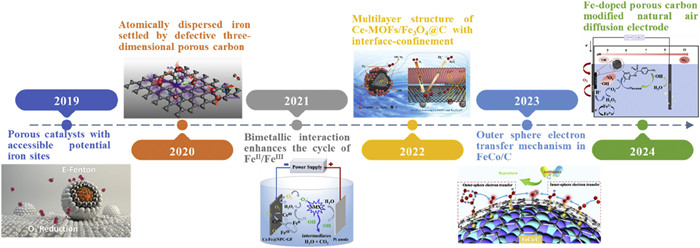
Fig. 2 illustrated the development timeline of MOFs−derived electrocatalysts. In 2019, Liu et al. [48] used calcined MOFs anchored on porous carbon monolithic substrates, which ensured that potential Fe sites both available for •OH generation. It marked the first instance of a MOFs−derived electrocatalyst with a nanoconfinement applied to the 3e− ORR in water treatment. Subsequently, in 2020, Cao et al. [49] demonstrated that atomically−dispersed Fe sites within defective three−dimensional porous carbon exhibited a 59-folds improvement in the elimination of refractory toxic pollutants compared to nanoparticulate iron oxides. The introduction of bimetals such as Fe/Ce, Fe/Cu, Fe/Co, and Fe/Mn into porous carbon has since become a research hotspot, enhancing the Fe(Ⅲ)/Fe(Ⅱ) cycle in the 3e− ORR [50-53]. In 2022, Su et al. [54] reported that the confinement between the interface of Ce-MOFs and Fe3O4@C facilitated O2 adsorption at the ORR fountainhead, thereby reducing the required external potential. Following this, the integration of nanoconfinement and bimetallic strategies was further developed [55]. To enhance the efficiency of MOFs derivatives in promoting the 3e− ORR, various strategies should be explored, such as loading substrates like natural air diffusion electrodes or binding with other carbon materials like carbon aerogel [56,57].
Figure 2
Figure 2.
Timeline of the representative development of MOFs derivatives as electrocatalysts. Reproduced with permission [48-50,54-56]. Copyright 2019, 2020, American Chemical Society. Copyright 2021, 2022, 2023, 2024, Elsevier.
Transition metals, particularly iron, demonstrate substantial reactivity in the activity of H2O2, which is crucial in electrocatalytic technology [58]. As a result, the design and regulation of MOFs precursors are crucial in shaping the structure of electrocatalysts. This, in turn, directly impacts the pollution removal performance of electrocatalytic process. The morphology of metal-modified carbon electrocatalysts, obtained from MOFs, can be classified into three types: (1) Metal dispersion on the nanocarbon surface; (2) metal nanoparticles embedded within a carbon shell; (3) atomically dispersed metal anchored in porous carbon. These different morphological structures have varying effects on the efficiency and effectiveness of the electrocatalytic reactions.
3.1
Metal dispersion on the nanocarbon surface
Direct pyrolysis of MOFs is a simple and convenient technique to obtain metal−modified carbon electrocatalysts, leading to the uniform dispersion of metal nanoparticles on a porous matrix. This dispersion enhances catalytic performance by facilitating increased contact between pollutants and metal nanoparticles [59]. The use of the solvothermal method with H2BDC or 2−aminoterephthalic acid (NH2−H2BDC) ligands is crucial for preparing iron−based materials (MILs (Fe)), including MIL−53(Fe), MIL−88(Fe) and MIL−101(Fe), originating from the Lavoisier Institute. MIL−88(Fe) is characterized by an unlimited skeleton with 3D channels produced by secondary building units (SBUs) composed of [Fe3(μ3nullO)(COO)6(H2O)2Cl]6 and H2BDC linkers. In contrast, MIL−101(Fe) features quasi−spherical cages created by Fe3O−carboxylate trimer SBUs and H2BDC linkers. These mesoporous cages have a size of 2.9 nm × 3.4 nm and can be accessed through micropore windows of 1.2 and 1.6 nm. MIL−101(Fe) and MIL−100(Fe) both exhibit mesoporous cages formed by iron octahedra trimers of [(Fe3(m3nullO))(OH)(H2O)2]6 SBUs and 1,3,5-benzenetricarboxylic acid linkers. However, MIL-100(Fe) has smaller microporous apertures (0.55 and 0.86 nm) compared to MIL−101(Fe), despite having similar mesoporous cage dimensions (2.5 and 2.9 nm). Liu et al. [48] investigated how the topology of MILs (Fe) affects the electrocatalytic performance of their derivatives. Their study revealed that the resulting structures depend on the identity of the functional group and organic linker, leading to the identification of Fe3C as the iron component in derivatives of NH2−MIL−88(Fe).
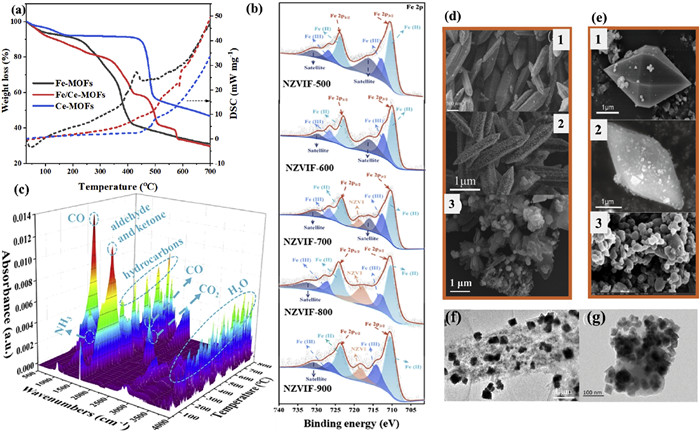
The critical role of pyrolysis temperatures in influencing the resulting metal species is well recognized, with temperature exceeding 400 ℃ leading to the decomposition of organic ligands in H2BDC and Fe−O coordination bonds in MOFs, forming iron oxides (Fig. 3a) [54]. For examples, upon calcination in an inert gas atmosphere, NH2−MIL−88B(Fe) formed iron oxides−doped porous carbon (PC) at 450−650 ℃. At 800 ℃, it gradually transformed into Fe0 and Fe3 N, and at 1000 ℃, only Fe0 species remained [56,60]. Similarly, the pyrolysis of MIL−101(Fe) at temperatures ranging from 450 ℃ to 650 ℃ initially forms iron oxides, evolving into Fe0 and Fe3C beyond 650 ℃ (Fig. 3b) [61]. The three−dimensional thermogravimetric Fourier transform infrared spectra (3D TG−FTIR), increasing the pyrolysis temperature led to the production of CO, facilitating the transformation of Fe species and the eventual production of Fe0 (Fig. 3c). The presence of both iron oxides and Fe0 enhanced the rate of H2O2 activation.
Figure 3
Figure 3.
(a) TGA and DSC curve of Fe−MOFs, Fe/Ce−MOFs and Ce−MOFs. Reproduced with permission [54]. Copyright 2022, Elsevier. (b) Fe 2p XPS spectra and (c) 3D TG−FTIR spectra of nano Fe0 modified porous fiber electrodes (NZVIF). Reproduced with permission [61]. Copyright 2023, Elsevier. (d) SEM images of MIL−53(Fe), FeCu−N doped C (Fe1Cu2−NC) and Ce/Fe@C. Reproduced with permission [53,57]. Copyright 2024, Elsevier. (e) SEM images of Fe/Cu−NH2−BDC, Fe/Cu−C400Ar and Fe−PC(800). Reproduced with permission [56,60]. Copyright 2023 and 2024, Elsevier. (f) TEM image of Mn/Fe@PC. Reproduced with permission [51]. Copyright 2020, Elsevier. (g) TEM image of Fe/Cu−C400Ar. Reproduced with permission [60]. Copyright 2023, Elsevier.
Customizing MOFs precursors is an effective method for achieving the desired morphology of electrocatalysts. Derivatives typically closely reflect the morphology of their precursors, especially at a pyrolysis temperature was 400 ℃ (Figs. 3d and e). For instance, FeCu−N doped carbon electrocatalysts exhibit a rod−like spindle structure for MIL−53(Fe) [53], and Ce−modified iron−based MOFs derivatives (Ce/Fe@C) showcases a bipyramidal hexagonal prism morphologies for MIL−88B(Fe) [60]. The slight porosity of the carbon formed on the polyhedron surface at low temperature from the carbonization of MOFs precursor was inadequate. However, increasing the pyrolysis temperature above 650 ℃ prompts MOFs precursor frame collapse, altering derivate morphologies (Figs. 3f and g). Successful N doping enhances atomic utilization efficiency and modifies the spin density and charge distribution within the carbon structure, creating an uneven configuration that reduces interface transfer resistance [62]. Integrating N atoms into metal−incorporated carbons stabilizes metals and enhances derivate performance characteristics [63]. Multiple strategies exist for incorporating N species into MOFs, such as using N−containing ligands like NH2−H2BDC [64] or external sources like polyacrylonitrile (PAN) [61] and ammonia atmosphere [65]. Pyrolysis at different temperatures yields distinct N species, including graphite N, pyrrole N, pyridine N, their oxides, and metal−N bonds. Recent research suggests that metal−N coordination primarily promotes 4e− ORR, potentially undermining the performance of 3e− catalysts [66,67]. Nevertheless, single−atom catalysts (SACs) with high atomic utilization efficiency exhibit potential in addressing this limitation, a topic to be further investigated later. The coordination of metals, particularly Fe with N is crucial for ORR selectivity. Increased coordination enhances the likelihood of a 4e− ORR.
The incorporation of binary metals into MOFs−derived hybrid micro−/nano−materials significantly enhances the stability and long−term performance of electrocatalytic technology. In the preparation of Fe−MOFs, metal salts (Mn, Co, Ni, Cu, Ce) are introduced to create binary metal−based MOFs. The process and evolution mechanism of bimetallic MOFs are complex. The addition of metal ions does not disrupt the morphology and crystal structure of Fe−MOFs. For instance, the introduction of Mn results in additional defect sites in PC derived from MIL−53(Fe) and a microporous structure in PC derived from MOF−74, respectively [51,68]. Introducing CuBDC (Cambridge Crystallographic Data Centre (CCDC) 687, 690) with a cubic layered structure into NH2−MIL-88B(Fe) induces an increase in defects [69]. Co aids in transforming of high−valent metals to low−valent metals, while synergy with Fe enhances the graphitization degree of the electrocatalyst [64]. Moreover, Co/Fe−NPC derivatives from Co/MIL-101(Fe) at 500 ℃ displays enhanced mesopores, illustrating a hierarchical porous structure with microporous and mesoporous that offers additional attachment sites for Fe and Co clusters [52]. The inclusion of Ce enhances oxygen vacancies, promoting electron transfer and enhancing oxygen storage [57]. MOF(Fe) and MOF(Ce) precursors, featuring octahedral and flower-like structures respectively, yield Ce/Fe−nanoporous carbon with numerous oxygen vacancies from CeO2 after pyrolysis, thereby enhancing electron transport [50].
3.2
Metal nanoparticles embedded within a carbon shell
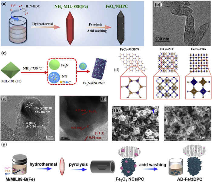
To fully exploit the electrocatalytic potential of composite iron nanoparticles doped carbon materials, it is crucial to ensure that all potential Fe sites are readily accessible on a porous electrocatalysts [70]. Enhanced •OH production is hindered by the limited surface contact percentage of Fe [71]. Metal dispersion on nanocarbon surfaces, especially in acidic electrolytes, enhances metal nanoparticles, significantly altering their physical and chemical properties compared to the bulk structure. This phenomenon is known as the nanoconfinement effect [72,73]. An innovative and efficient method for synthesizing M@C catalysts (metal nanoparticles embedded within a carbon shell) through the controlled pyrolysis of MOFs was proposed, where MOFs serve as precursors for both metal nanoparticles and carbon shells. By adjusting the pyrolysis conditions of metal ions, organic ligands and MOFs, the resulting product, namely the structure of M@C, can be customized. For instance, calcination of NH2−MIL-88B(Fe) at 750 ℃ for 2 h, next by HCl etching to form N−doped hierarchical PC encapsulated FeOX nanoparticles (FeOX/NHPC) (Fig. 4a), resembling a bipyramidal hexagonal prism with iron particles dispersed within the carbon matrix (7 nm) (Fig. 4b) [74]. Furthermore, Cu2+ was embedded with molecular−scale cages of NH2−MIL-88B(Fe) utilizing the hydrothermal method [63]. Subsequently, iron oxide encapsulated in Cu, N co−doped hollow PC (FeOX/CuNXHPC) catalysts were synthesized by one−step carbonization. Another method used to generate M@C derived from MOFs is ammonia etching. Xiao et al. [65] synthesized Fe3 N particles encapsulated in N−doped graphite carbon by treating MIL-101 (Fe) with flowing ammonia gas at 750 ℃ for 1 h (Fig. 4c). The structure of graphitic carbon coating effectively prevents the leaching (0.03 mg/L) and aggregation of Fe3 N nanoparticles.
Figure 4
Figure 4.
(a) Schematic diagram of FeOX/NHPC preparation and its (b) TEM images. Reproduced with permission [74]. Copyright 2020, Elsevier. (c) Schematic diagram of Fe3N@NG/NC preparation. Reproduced with permission [65]. Copyright 2021, Elsevier. (d) MOFs precursors of Fe/Co ions (FeCo−ZIF, FeCo−MOF74 and FeCo−PBA) complexed with different linkers (MeIM, DHTA and cyanide). Reproduced with permission [55]. Copyright 2023, Elsevier. (e) TEM images of Co@N−C. Reproduced with permission [76]. Copyright 2018, Elsevier. (f) HRTEM image of Ce−MOFs/Fe3O4@C. Reproduced with permission [54]. Copyright 2022, Elsevier. (g) Schematic diagram of AD−Fe/3DPC preparation. SEM images of Cu/MIL−88B(Fe) precursor pyrolysis products (h) without acid washing and (i) with acid washing. Reproduced with permission [49]. Copyright 2020, American Chemical Society.
The precursor composition of MOFs has a significant impact on the structure and functional properties of pyrolysis products [75]. A higher carbon−to−metal ratio in MOFs enhances conductivity, porosity, stability, and carbon shell thickness. Conversely, a lower ratio may lead to incomplete metal core coverage, adversely affecting the performance and stability of the final products. Cheng et al. [55] utilized MeIM, 2,5-dihydroxyterephthalic acid (DHTA), and cyanide ligands to synthesize FeCo-ZIF, FeCo-MOF74 and FeCo-PBA (PBA: Prussian blue analogue), respectively (Fig. 4d). Subsequently, the FeCo-ZIF was pyrolyzed to generate FeCo@C, which demonstrated superior stability characterized by undetectable Fe leaching and 0.09 mg/L Co leaching. Moreover, ZIF-67 was subjected to calcination in a 10% H2/Ar atmosphere at 600 ℃ to produce CNTs encapsulated with Co nanoparticles (Co@N−C) (Fig. 4e). Co nanoparticles in Co@N−C were protected by a thin crystalline carbon layer measuring 1−4 nm in thickness, serve to shield them from acidic dissolution [76]. The morphology of M@C electrocatalysts presents a more promising approach for developing efficient 3e− ORR. Electrons could be transferred from the internal active transition metal to the surrounding carbon shell [77]. This electron transfer alters the local electronic environment of the carbon shell, thereby improving the efficiency of H2O2 activation and increasing the selectivity of 3e− ORR.
Based on crystalline structures of MOFs-derived catalysts, their unique structural transformations and performance variations following pyrolysis are linked to the diverse thermal stability properties of MOFs. Su et al. [54] synthesized single crystal structures of Ce−MOFs and MIL−88B(Fe) through the solvothermal method, using iron acetylacetonate, cerium(Ⅲ) nitrate hexahydrate, and H2BDC. It shows that the Ce−MOFs exhibit higher thermal stability at temperatures below 450 ℃, in contrast to Fe−MOFs and Fe/Ce−MOFs, which decompose at lower temperatures ranging from 250 ℃ to 350 ℃ (Fig. 3a). After calcinating Fe/Ce−MOFs at 400 ℃, Fe elements were embedded in the carbon layer, resulting in the formation of Fe3O4@C. Moreover, the Ce−MOFs, composed of spindle−like singular building units, were evenly spread across the carbon layer surface (Fig. 4f). The interaction between Ce−MOFs and Fe3O4@C results in the generation of oxygen vacancies, underscoring a significant confinement effect at this interface that enhances O2 adsorption.
3.3
Atomically dispersed metal anchored in porous carbon
Bulk metal electrocatalysts that are supported often exhibit poor catalytic performance and stability, along with poor exposure and utilization of active sites in bulk electrocatalysts, as well as low resistance to acidic and cORRosive environments [71,78]. In contrast, SACs stand out due to their unique structure of atomically dispersed metal sites supported on specifically suited substrates, which allows for the maximum utilization rate of metal centers. This unique structural feature not only enhances catalytic performance but also ensures chemical stability [79]. Therefore, SACs effectively combine the benefits of both homogeneous and heterogeneous catalysts. For instance, the Cl-doped single-atom Fe heterogeneous catalyst (FeCl2CX/PC) was developed by introducing Cl atoms into a carbon substrate derived from MIL−88B(Fe), resulting in Fe leaching of < 0.02 mg/L, significantly lower than that of iron nanoparticles (Fe@Fe3O4/PC) at around 0.10 mg/L [80].
Atomically distributed M-NX-C SACs have been widely recognized for their effectiveness in the ORR process [81]. Recent advancements have showcased the excellent selectivity of FeSA-OX-C, CoSA-NX-C and PtSA-SX-C in catalyzing a highly specific 2e− pathway for producing the valuable chemical H2O2 [43,82,83]. Furthermore, the geometric and electronic structures of SACs is strategically modified through changing the metal sites, altering adjacent coordinative heteroatoms, or adjusting coordination configuration and unsaturation [84]. This tunability empowers control over reaction behaviors and product selectivity, allowing the facilitation of a 3e− pathway for the specified conversion of O2 to •OH [43,85]. Cao et al. [49] introduced Cu2+ from copper salt into MIL-88B(Fe) to obtain Cu/MIL-88B(Fe). Under an inert atmosphere, Cu/MIL-88B(Fe) underwent thorough acid−leaching method result in the removal of Cu particles and iron that is not firmly bonded, resulting in iron single-atom anchored on 3D porous carbon (AD-Fe/3DPC) (Fig. 4g). The AD-Fe/3DPC features a significantly large surface area and open pore channels, attributed to the Cu2+ auxiliary synthetic process of AD-Fe/3DPC, even though other assisted ions such as Al3+, Cr3+, or Zn2+ could potentially hinder this process.
During the production of SACs, the acid etching process utilizing HCl and H2SO4 on metal distributed on porous carbon is crucial. Before acid treatment, A large amount of FeOx particles, each measuring 600 nm, are visible in the FeOx dispersed on PC (Fig. 4h). However, these particles are absent in the acid−treated AD-Fe/3DPC (Fig. 4i). Carbon defects serve as stable anchoring sites for Fe atoms, while doped Cl atoms can coordinate with unsaturated Fe sites, recognized as the active centers for the 3e− [80,86]. The SACs strategy can adjust the electronic structure of electrocatalyst, increase electron density, enhance O2 adsorption and reduction, expand the reaction surface area, and provide effective ORR sites.
Compared to the electrocatalysts of iron dispersed on nanocarbon surface, morphologies of M@C and SACs are more easily regulated to achieve highly selective 3e− ORR. Despite advancements, significant limitations remain in precisely controlling the structural components of MOFs derivatives and understanding their interactions with ORR products. In−situ characterization techniques, for examples in−situ TEM, are crucial for observing the transformation mechanisms and catalytic active phases of MOFs under varying conditions, particularly for morphology control and screening [87]. These techniques can be effectively combined with in−situ XRD [88] and in−situ XPS [89]. Additionally, in−situ Raman spectroscopy [90], in−situ attenuated total reflectance surface−enhanced infrared absorption spectroscopy [91], and in−situ Fourier transformed infrared spectroscopy [58] are valuable for observing the O − O stretching vibrations of electrocatalysts in ORR, as well as surface adsorption *OOH, *H2O2, and C−H groups of pyridine rings. These observations can provide guidance for regulating ORR selectivity. Currently, there is limited focus on targeting multiple active sites in MOFs derivatives. However, employing in−situ techniques for electrocatalyst derivation and ORR reaction identification can facilitate the examination of these electrocatalysts under realistic conditions, aiding in the screening of highly selective 3e− ORR electrocatalysts.
4.
Regulation of •OH production in MOFs derivatives
In recent years, extensive research on MOFs-derived electrocatalysts with diverse morphologies and structures has made them a focal point in the field of EAOPs [92,93]. These catalysts are favored for their inherent advantages, including exposed surface area, porous structure, and customizable catalytic centers [94]. MOFs derived electrocatalysts are known to engage in a (2 + 1)e− ORR process to produce •OH, which efficiently degrade pollutants.
4.1
Promotion of 1e− to •OH
In the electrocatalytic process, •OH generated by the Haber Weiss cycle is the primary oxidative intermediate at the aqueous interface [13]. Traditional metals and their oxides, which are formed during the derivation of MOFs, provide numerous active sites for the 1e− activation of H2O2 [95,96]. To ensure the effective generation of •OH, a significant amount of H2O2 production is essential. An effective method to enhance H2O2 generation involves incorporating external N sources into MOFs to produce derivatives. Introducing N atom into the MOFs derivatives modifies the electronegativity of carbon atoms, resulting in the creation of positive charge sites [97]. These sites promote the adsorption of O2 on the surface, facilitating increased H2O2 production. The synthesis of porous composite materials involving Fe2O3/N—C utilized MIL-100(Fe) and MIL-53 (Fe) as precursors, with polyaniline (PANI) as the N source [98]. Comparative analysis revealed that Fe2O3/N—C derived from MIL-100 (Fe) surpassed that derived from MIL-53 (Fe) in terms of H2O2 production and pollutant removal efficiency. The higher activity of MIL-100(Fe) is mainly due to the lower content of C—N bonds formed between PANI and MIL-53. Another effective approach involves preparing MOFs precursors with N−containing ligands, which requires a higher nanocarbon content and low metal content (< 5 at%). However, a challenge arises with N−containing ligands due to the significant coordination between metals and N atoms, potentially shifting the ORR from a 2e− process to a 4e− process [99,100]. The FeOX/NHPC catalysts, derived from NH2−MIL−88B(Fe) using NH2-H2BDC as ligand, exhibited a remarkable H2O2 selectivity ranging from 95% to 98% at potentials −0.3 V ~ −0.8 V (vs. SCE), surpassing that of FeOX/HPC (30%−60%) [74]. Furthermore, the rate constant value (k) for phenol removal by the FeOX/NHPC cathode was 0.034 min−1, twice as high as that of the FeOX/HPC cathode.
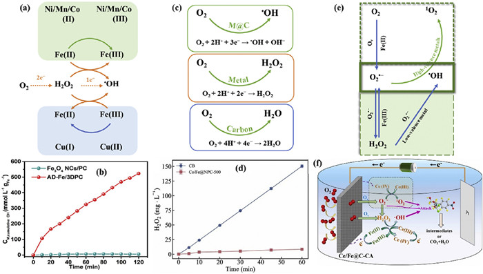
Enhancing the cycles of Fe(Ⅲ)/Fe(Ⅱ) on the electrocatalyst surface is an effective strategy to boost •OH production and facilitate efficient pollutant degradation (Fig. 5a) [101]. Incorporating other metals is an effective means to facilitates the Fe(Ⅲ)/Fe(Ⅱ) cycle based on redox potential values of Fe(Ⅲ)/Fe(Ⅱ) (0.77 eV) [102]. For instance, the standard electrode potential for Cu(Ⅱ)/Cu(Ⅰ) is 0.17 V, making the Fe(Ⅲ) reduction by Cu(Ⅰ) thermodynamically feasible [103]. Moreover, Cu(Ⅱ)is more easily reduced by H2O2 because of high reaction rate (4.6 × 10² L mol−1 s−1) [104]. This synergistic effect is evident in Fe/Cu−C, which demonstrated complete removal of ceftazidime (CAZ) within 120 min while maintaining similar levels of Fe(Ⅱ) and Cu(Ⅰ) before and after the reaction, thereby enhancing the electrochemical activity compared to Fe−C [60]. FeOX/CuNXHPC achieved a phenol removal rate of 93%, significantly higher than the 46% achieved with FeOX/NHPC, due to the more efficient conversion of H2O2 to •OH on FeOX/CuNXHPC, facilitated by Cu(Ⅰ) accelerating the Cu(Ⅰ) cycle [63].
Figure 5
Figure 5.
(a) The strategy of promotion of cycle of Fe(Ⅲ)/Fe(Ⅱ) to generate to •OH. (b) Mass activity in •OH productivity of AD−Fe/3DPC and Fe3O4 NCs/PC catalytic systems. Reproduced with permission [49]. Copyright 2020, American Chemical Society. (c) The scheme of direct conversion of O2 to •OH via 3e− ORR. (d) The H2O2 accumulation with Co/Fe@NPC cathodes. Reproduced with permission [64]. Copyright 2023, Elsevier. (e) The scheme of interaction between •OH and O2•−. (f) Schematic mechanism of Ce/Fe@C in heterogeneous EF. Reproduced with permission [57]. Copyright 2024, Elsevier.
Compared to Cu, Mn (Ⅲ) has a higher standard reduction potential of 1.54 V and a greater electron acceptance rate, leading to more readily regeneration of Mn(Ⅱ)compared to Fe(Ⅱ) [105]. This promotes the activation of H2O2 for generating •OH and degrading pollutants. Mn/Fe@PC, derived from Mn-doped MIL-53(Fe) precursor, expedited triclosan degradation within 120 min, achieving 56.9% total organic carbon removal within 240 min at 40 mA and pH 3 [51]. Co(Ⅱ)with a standard reduction potential of 1.83 V for Co(Ⅲ) [106], when involved in the Fe(Ⅲ)/Fe(Ⅱ) cycle, increased •OH generation, resulting in increased removal efficiency of Cu−ciprofloxacin complexes (Cu-CIP) from 40% to 60% [52]. Furthermore, the substantial difference in standard reduction potentials, with Ni(Ⅲ)/Ni(Ⅱ)at 1.74 V being considerably higher than Fe(Ⅲ)/Fe(Ⅱ), promotes the conversion of Ni(Ⅲ) to Ni(Ⅱ)through interaction with Fe(Ⅱ) [102]. This interaction is exemplified by FeNi3@C electrocatalysts, which achieved an impressive 95.4% oxytetracycline (OTC) degradation within 90 min [107]. These findings collectively underscore the potential of incorporating various metals to enhance the Fe(Ⅲ)/Fe(Ⅱ) cycle, thereby improving the efficiency of pollutant degradation through electrocatalysis.
Modifying the electronic environment of metal centers to enhance •OH production is an effective strategy for effective pollutant removal [85]. SACs exhibited extremely high •OH yield. For instance, the AD−Fe/3DPC catalysts exhibited a •OH productivity of 523.2 mmol L−1 gFe−1 at 120 min, which is 77 times greater than that of the iron oxide dispersed on PC (Fe3O4 NPs/PC) electrocatalyst (Fig. 5b) [49]. Consequently, the k value of degradation for sulfamethoxazole (SMX) on AD-Fe/3DPC reached 6.12 h−1, nearly tripling that of Fe3O4 NPs/PC. Moreover, FeCl2CX/PC electrocatalysts reported by Ren et al. could generate 37.86 mg/L H2O2 at 60 min, which was then reduced to •OH via a 1e− reaction to effectively degrade amoxicillin (AMX) completely within 15 min [80].
4.2
Direct conversion of O2 to •OH via 3e− ORR
It can be challenging to attain equilibrium in electron transfer during electrocatalytic processes due to electron competition processes, such as the 2e− process of generating H2O2 and the 1e− process of decomposing H2O2 to produce •OH [108,109]. To improve electron utilization efficiency and enable rapid pollutant degradation, it is crucial to ensure that the generated H2O2 rapidly decomposes into •OH. This will facilitate a continuous 3e− ORR process instead of a (2 + 1)e− process (Fig. 5c). Consequently, the accumulation of H2O2 during the electrocatalytic process remains minimal. The N−doped porous carbon containing CoFe alloy (CoFe@NPC) derived from NH2−MIL−88(Fe) with Co(NO3)2·6H2O exhibited H2O2 generation of 8.3 mg/L at 40 mA current (Fig. 5d) [64]. The Co/Fe@NPC exhibited significantly higher CAZ degradation efficiency (100%) compared to other electrocatalysts, indicating its superior performance. This enhanced catalytic activity is likely due to accelerated electron transfer within the CoFe alloy, which increases both H2O2 production and its subsequent breakdown. Moreover, the in−situ generation of H2O2 (5 mg/L) on the Ce/Fe@NPC catalyst facilitated the rapid conversion of H2O2 into •OH, benefiting from the synergy effects of Fe(Ⅱ) and Ce(Ⅲ) [50]. The strategy represents an innovative approach to •OH production from the electrocatalytic reduction of O2, effectively resisting the rate−limiting step of electron transfer typically encountered in the reduction/oxidation cycle of the Fenton process [77].
4.3
Interaction between •OH and O2•−
The interactions between •OH and O2•− can be categorized as follows (Fig. 5e): (1) O2•− can enhance •OH yield; (2) O2•− can consume •OH to produce other ROS and (3) synergistic effects of multiple ROS for pollutants removal were exhibited. O2•− (E0(O2•−/H2O2) = 0.93 V) [110] are typically generated by activating of O2 or H2O2 in the role of high-valence metals. Notably, O2•− can facilitate the in−situ production of H2O2 through 1e− reduction to increase •OH yield [111], leading to the enhancement of •OH yield from 0.03 mmol/L to 0.109 mmol/L at 90 min [107]. However, it is notable that O2•− can eliminate •OH, especially surface-bound •OH (•OHsur.), resulting in the production of 1O2 [61,112]. Despite having a lower oxidation ability than •OH, 1O2 (E0(1O2/ O2•−) = 0.65 V), has attracted significant attention for its longer lifespan, better tolerance of pH, and improved selectivity for pollutants removal [58]. A critical factor in leveraging 1O2 for pollutant degradation is the efficient conversion of O2•− to 1O2. Metals other than Fe can effectively enhance the production of 1O2, as seen in the case of Ce(Ⅳ) in Ce/Fe@C bifunctional electrocatalysts that promotes the formation of 1O2 [57]. Several studies have shown that •OH and 1O2 collaborate in the oxidation and elimination of pollutants in the presence of O2•− (Fig. 5f). However, their contributions to pollutants removal vary depending on pH values, with •OH being highly reactive in acidic conditions and 1O2 exhibiting significant pH tolerance. For instance, Fe−PC demonstrated a higher 85% removal of sulfamethazine (SMT) across wide pH range of 3 to 11 through the combined action of •OH and 1O2 [56].
5.
Advantages of MOFs derivatives as 3e− electrocatalysts
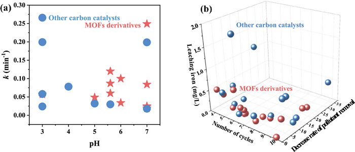
MOFs derivatives offered distinct advantages over other carbon−based metal catalysts due to their inherent structural properties. The high porosity and large surface area greatly improved access to active sites and catalytic centers [113,114]. Furthermore, MOFs derivatives exhibited a high dispersion of heteroatoms and uniformly distributed metal nanoparticles [115]. This uniform distribution plays a crucial role in regulating defects and optimizing metal utilization, thereby improving catalytic performance [70]. The k value of pollutants removal of MOFs derivatives and other carbon−based materials as 3e− ORR electrocatalysts was compared (Fig. 6a). This indicated that MOFs derivatives exhibited superior catalytic activity for pollutants removal within the pH range of 5–7, while other carbon−based materials performed better at a pH 3. Typically, the pH of wastewater is neutral [116], suggesting the potential of MOFs derivatives for purifying water bodies.
Figure 6
Figure 6.
(a) Comparison of k value of pollutants removal at different pH of MOFs derivatives in Table 1 and other carbon−based materials as 3e− ORR electrocatalysts in the literature. (b) Comparison of cycles number, decrease in pollutant removal efficiency and leaching iron concentration of MOFs derivatives in Table 1 and other carbon−based materials as 3e− ORR electrocatalysts in the literatures [10,11,58,78,112,117-124].
N: Number of cycles; NOR: norfloxacin; SCZ: secnidazole; CA: carbon aerogels; CAP: chloramphenicol; BPA: Bisphenol A; AO7: Acid Orange 7; RhB: rhodamine B.
Assessing the industrial potential and applications of 3e− ORR electrocatalysts hinges on their stability. The sustained efficacy of these electrocatalysts significantly relies on the stability and regeneration activity. Although electrocatalysts may exhibit a slight decrease in performance after 4–10 cycles in pollutant removal, they can still maintain an 80% removal (Table 1). The primary reasons for this decline are the leaching of active metals or deactivation of metal active sites. Notably, the leached iron concentration remains below the permissible limits established by the discharge standards in the European Union (< 2.0 mg/L) and the United States (< 1.3 mg/L) [56]. Furthermore, other metals also conform to the permissible limits set by various Chinese standards, such as municipal wastewater treatment plants (Mn < 2.0 mg/L), water environment discharge standards (Co < 1 mg/L and Ce < 1 mg/L for GB 25467−2010; Ni < 0.5 mg/L for GB 21900−2008), Ⅱ−level national standard for surface water (Cu < 1 mg/L for GB3838–2002) [51,57,60,64,107]. Among various carbon−based materials, such as FeOCl/O−CNTs, Fe0−in−CNTs, and Fe@BN−C, MOFs derivatives have demonstrated superior performance as 3e− ORR electrocatalysts (Fig. 6b). Notably, these MOFs derivatives exhibit a lower decrease in pollutant removal efficiency and reduced iron leaching after multiple cycles [117-124]. This indicates their enhanced stability and reusability compared to other carbon−based materials when used as ORR electrocatalysts.
The maintenance of metal active sites on the surfaces of electrocatalysts is pivotal for achieving high efficiency in 3e− ORR. Notably, the morphology and structure of MOFs−derived electrocatalysts remain unchanged following 3e− ORR reactions [50,53,107]. The reusability and activity of these electrocatalysts can be augmented by promoting Fe(Ⅲ)/Fe(Ⅱ) cycling. Remarkably, the Fe(Ⅱ) content on the FeOX/CuNXHPC used is approximately 19 times that of similar electrocatalysts, while after the same treatment, the content on FeOX/NHPC only increased threefold [63]. FeOX/CuNXHPC maintains a 97% phenol removal after ten consecutive operations without regeneration, unlike FeOX/NHPC, whose performance declines after just five operations [63,74].
6.
Conclusions and perspective
6.1
Conclusion
This work provides an overall review of the main process for improving the process of 3e− ORR in electrocatalysts derived from MOFs. The study emphasizes the importance of selecting and designing the morphology and active sites of MOFs derivatives to optimize their performance. These active sites are crucial for effectively generating H2O2 from 2e− and further activate H2O2 to form •OH with 1e−. Understanding this vital mechanism is essential to regulate 3e− ORR in EAOPs and ensuring effective wastewater treatment. Notably, the key method for MOFs derivatives to achieve the H2O2 production of 2e− of involves the design of porous carbon or Co/N co−doped carbon materials. To enable electron activation of H2O2 to •OH, strategies such as metal dispersion on nanocarbon surfaces, embedding in carbon shells, and dispersing metal atoms anchored within porous carbon are employed. The mechanisms utilized by MOFs derivatives to facilitate •OH production and consequently wastewater purification include promoting the Fe(Ⅱ)/Fe(Ⅲ) cycle, facilitating direct 3e− reactions of O2, and influencing the generation of O2•−. Consequently, this review provides valuable insights into the mechanisms by which MOFs derivatives function as electrocatalysts for ORR selectivity, establishing a solid foundation for their active sites and offering a roadmap for the development of sustainable water treatment technologies.
6.2
Challenges and outlook
Despite advancements in the advancement of MOFs derivatives for 3e− ORR, several unresolved issues persist that must be addressed to improve their application in wastewater purification.
(ⅰ) Elucidating the growth mechanisms of various MOFs derivatives is crucial for accurately regulating their structure and composition, as the growth mechanisms of most MOFs derivatives remain unclear. The dispersed form of metal active sites within porous carbon is particularly important, as it significantly influences the activity and stability of electrocatalysts.
(ⅱ) Identifying the interrelationships and evolutionary mechanisms between these competitive reactions and ORR is crucial in gaining a clear understanding of the reactivity and selectivity of ORR products. MOFs derivatives often contain multiple active sites that can facilitate various competitive reactions, such as those initiated by other reactive species, in addition to ORR.
(ⅲ) The high selectivity of the 3e− ORR and the limited identification of active sites pose challenges. Key factors controlling the direct 3e− ORR from O2 to •OH remain unclear despite their potential to address the rate−limiting steps in H2O2 production and activation in EAOPs. Investigating the atomic−level dynamics of catalysts is crucial for elucidating the relationship between active sites, ORR intermediates, and the high selectivity of the 3e− ORR.
(ⅳ) Current studies on electrochemical systems predominantly focus on laboratory−scale investigations, primarily due to the complexities involved in preparing electrocatalysts and their cathodes. However, there is a significant gap in research concerning crucial aspects such as the reusability of catalysts and the design and development of pilot reactors and equipment. Addressing these areas is essential for advancing the practical application and scalability of electrochemical technologies.
Declaration of competing interest
The authors declare that they have no known competing financial interests or personal relationships that could have appeared to influence the work reported in this paper.
CRediT authorship contribution statement
Xifeng Lu: Writing – original draft, Investigation, Data curation, Conceptualization. Pei Su: Writing – review & editing, Supervision, Funding acquisition, Conceptualization.
Acknowledgments
This work was financially supported by National Natural Science Foundation of China (No. 22302170) and Science Research Project of Hebei Education Department (No. QN2024256).
Figure 1
Schematic diagram of (a) HPC preparation, (b) the M−N−C catalysts (M = Co, Ni, Fe, Cu, and Mn), and SEM image of the Co−N−C catalyst, (c) CoSA−N−CNTs and CoNP−N−C catalysts preparation and (d) the oxo CoNCF catalysts preparation. Reproduced with permission [36,44,45,47]. Copyright 2015, Wiley; 2019, American Chemical Society and 2022, Elsevier, respectively.
Figure 2
Timeline of the representative development of MOFs derivatives as electrocatalysts. Reproduced with permission [48-50,54-56]. Copyright 2019, 2020, American Chemical Society. Copyright 2021, 2022, 2023, 2024, Elsevier.
Figure 3
(a) TGA and DSC curve of Fe−MOFs, Fe/Ce−MOFs and Ce−MOFs. Reproduced with permission [54]. Copyright 2022, Elsevier. (b) Fe 2p XPS spectra and (c) 3D TG−FTIR spectra of nano Fe0 modified porous fiber electrodes (NZVIF). Reproduced with permission [61]. Copyright 2023, Elsevier. (d) SEM images of MIL−53(Fe), FeCu−N doped C (Fe1Cu2−NC) and Ce/Fe@C. Reproduced with permission [53,57]. Copyright 2024, Elsevier. (e) SEM images of Fe/Cu−NH2−BDC, Fe/Cu−C400Ar and Fe−PC(800). Reproduced with permission [56,60]. Copyright 2023 and 2024, Elsevier. (f) TEM image of Mn/Fe@PC. Reproduced with permission [51]. Copyright 2020, Elsevier. (g) TEM image of Fe/Cu−C400Ar. Reproduced with permission [60]. Copyright 2023, Elsevier.
Figure 4
(a) Schematic diagram of FeOX/NHPC preparation and its (b) TEM images. Reproduced with permission [74]. Copyright 2020, Elsevier. (c) Schematic diagram of Fe3N@NG/NC preparation. Reproduced with permission [65]. Copyright 2021, Elsevier. (d) MOFs precursors of Fe/Co ions (FeCo−ZIF, FeCo−MOF74 and FeCo−PBA) complexed with different linkers (MeIM, DHTA and cyanide). Reproduced with permission [55]. Copyright 2023, Elsevier. (e) TEM images of Co@N−C. Reproduced with permission [76]. Copyright 2018, Elsevier. (f) HRTEM image of Ce−MOFs/Fe3O4@C. Reproduced with permission [54]. Copyright 2022, Elsevier. (g) Schematic diagram of AD−Fe/3DPC preparation. SEM images of Cu/MIL−88B(Fe) precursor pyrolysis products (h) without acid washing and (i) with acid washing. Reproduced with permission [49]. Copyright 2020, American Chemical Society.
Figure 5
(a) The strategy of promotion of cycle of Fe(Ⅲ)/Fe(Ⅱ) to generate to •OH. (b) Mass activity in •OH productivity of AD−Fe/3DPC and Fe3O4 NCs/PC catalytic systems. Reproduced with permission [49]. Copyright 2020, American Chemical Society. (c) The scheme of direct conversion of O2 to •OH via 3e− ORR. (d) The H2O2 accumulation with Co/Fe@NPC cathodes. Reproduced with permission [64]. Copyright 2023, Elsevier. (e) The scheme of interaction between •OH and O2•−. (f) Schematic mechanism of Ce/Fe@C in heterogeneous EF. Reproduced with permission [57]. Copyright 2024, Elsevier.
Figure 6
(a) Comparison of k value of pollutants removal at different pH of MOFs derivatives in Table 1 and other carbon−based materials as 3e− ORR electrocatalysts in the literature. (b) Comparison of cycles number, decrease in pollutant removal efficiency and leaching iron concentration of MOFs derivatives in Table 1 and other carbon−based materials as 3e− ORR electrocatalysts in the literatures [10,11,58,78,112,117-124].

 DownLoad:

 下载:
下载:


