The interface engineering strategy assists the 3D core-shell structure Co3S4/CuS@NiFe LDH nanocoral spheres to achieve significant overall water splitting
Citation:
Jun Yu, Yangping Zhang, Nannan Zhang, Jie Li, Huiyu Sun, Xinyu Gu, Changqing Ye, Tianpeng Liu, Yukou Du. The interface engineering strategy assists the 3D core-shell structure Co3S4/CuS@NiFe LDH nanocoral spheres to achieve significant overall water splitting[J]. Chinese Chemical Letters,
2026, 37(2): 110830.
doi:
10.1016/j.cclet.2025.110830
The interface engineering strategy assists the 3D core-shell structure Co3S4/CuS@NiFe LDH nanocoral spheres to achieve significant overall water splitting
English
The interface engineering strategy assists the 3D core-shell structure Co3S4/CuS@NiFe LDH nanocoral spheres to achieve significant overall water splitting
College of Chemistry, Chemical Engineering and Materials Science, Soochow University, Suzhou 215123, China
b.
Jiangsu Key Laboratory for Environment Functional Materials, College of Materials Science and Engineering, Suzhou University of Science and Technology, Suzhou 215009, China
Received Date:
18 November 2024 Accepted Date:
06 January 2025 Revised Date:
26 December 2024 Available Online:
15 February 2026
Abstract:
Designing a highly active and stable bifunctional catalyst is essential for achieving superior overall water splitting (OWS). In this study, a three-dimensional (3D) core-shell structure Co3S4/CuS@NiFe LDH nanocoral spheres electrocatalyst was constructed on nickel foam (NF) via an interfacial engineering strategy. This 3D core-shell heterostructure maximizes the exposure of active sites, optimizes the charge transport pathway and accelerates gas release rates. The protective shell strategy of NiFe LDH provides favorable stability, which contributes to inhibiting the electrochemical corrosion of the electrocatalyst and mitigating the toxic effects of Cl− and other microorganisms during the seawater splitting process. Moreover, the introduction of NiFe LDH induces a change in the OER mechanism from an adsorption evolution mechanism (AEM) to a lattice oxygen mechanism (LOM), which improves the intrinsic activity of the catalyst. Consequently, Co3S4/CuS@NiFe LDH demonstrates exceptional performance in the oxygen evolution reaction (OER) (η100 = 251 mV) and in the hydrogen evolution reaction (HER) (η100 = 254 mV), alongside remarkable stability over 100 h. For OWS, it exhibits a voltage of 1.46 V at 10 mA/cm2 and maintain stability for 100 h. Impressively, Co3S4/CuS@NiFe LDH still possesses outstanding activity and stability in natural alkaline seawater. This work proposes interfacial engineering to construct bifunctional catalysts with core-shell heterostructures, providing instructive guidelines for the design of highly efficient electrocatalysts toward seawater electrolysis.
The combustion of conventional fossil fuels generates a significant quantity of pollutants, resulting in serious environmental pollution [1,2]. Meanwhile, the limited reserves of fossil fuels are aggravating the energy crisis. Energy shortages and environmental issues have enormously impacted the sustainable development of humanity [3]. Hydrogen energy is a powerful competitor to fossil energy owing to its high calorific value of combustion, abundant reserves and environmental friendliness [4,5]. Currently, the main methods for producing hydrogen are steam methane reforming, coal gasification and overall water splitting (OWS) [6]. Compared with the former two, OWS for hydrogen production is more environmentally friendly and has higher product purity. Therefore, hydrogen production from OWS is considered to be the most promising technology for future hydrogen production [7]. The OWS reaction consists of the hydrogen evolution reaction (HER) and the oxygen evolution reaction (OER) [8]. Nowadays, noble metal Pt-based and Ru/Ir-based catalysts are still advanced HER and OER materials. Nevertheless, low abundance and expensive price remain a major obstacle to their commercialization [9,10]. Therefore, exploring economical and stable non-noble metal catalysts is urgently needed.
Transition metal materials have gradually become strong competitors of noble metal catalysts owing to their high activity and low cost over recent years [11]. Due to their huge specific surface area (SSA), flexible electronic structure, and favorable stability, layered double hydroxides (LDHs) have become exceptionally promising non-noble metal catalysts in alkaline electrolytes. They also have enormous reserves and can be prepared in a cost-effective and simple manner [12-15]. Nevertheless, the intrinsic conductivity of LDH is poor, which diminishes the electron transfer rate during electrolysis, thus tremendously limiting its catalytic reaction kinetics [16,17]. Accordingly, it is significant to reasonably optimize the conductivity of LDH. Transition metal sulphides (TMSs) have high conductivity and potential high activity [18,19]. Combining them with LDHs can effectively strengthen the conductivity of the material, thereby increasing its catalytic performance. For instance, Cui et al. synthesized a FeCo2S4@CoFe LDH complex, which combines the advantages of LDH and TMS and shows favorable catalytic activity in both OER and HER [20]. Gong et al. assembled Ni(OH)S nanosheets and CoFe LDH nanosheets in an orderly manner to synthesize efficient and stable OER catalyst [21].
The catalytic performance of a catalyst is influenced by its structure [22]. The core-shell structure has unparalleled application potential in the field of OWS because of its large SSA, well-defined interfaces and speedy mass/charge transfer rate [9,23-26]. In addition, the coupling of the core material encapsulated in the shell with the shell material at the interface can result in interfacial synergistic effect and strong electronic interactions, leading to a significantly higher catalytic efficiency than that of a single component [27]. Moreover, the selection of compounds with excellent stability as the shell material can protect the core material from being oxidized easily during the electrolysis process, thus improving its stability in OWS and even overall seawater splitting [28]. There are many ways for constructing core-shell structures, and electrodeposition has been proven to be a convenient, fast and economical material synthesis method [29]. Electrodeposition growth of electrocatalysts on conductive substrates (NF) avoids the use of binders, decreases charge transfer resistance [30]. Furthermore, by making use of NF's inherent benefits, such as its superior conductivity, high porosity and large SSA, it is possible to maximize the charge transfer channel and quicken the bubble release rate [31,32]. This will optimize the intrinsic conductivity of the catalyst.
In this work, three-dimensional (3D) core-shell structured Co3S4/CuS@NiFe LDH nanocoral spheres were successfully synthesized on NF utilizing straightforward hydrothermal step and electrodeposition step. Benefiting from the advantages of the 3D core-shell structure and the synergistic effect between multi-component compounds, the Co3S4/CuS@NiFe LDH nanocoral spheres electrocatalyst represents peerless catalytic activity and stability. In alkaline solution, the catalyst only needs overpotentials of 251 mV (OER) and 254 mV (HER) to achieve a current density of 100 mA/cm2 and is found to be stable for 100 h. Subsequently, when this catalyst is employed for OWS, it displays ultra-low cell voltages of 1.46 (10 mA/cm2) and 1.59 V (50 mA/cm2) and impressive stability. Additionally, due to the favorable stability of the shell material NiFe LDH and its strong interfacial interaction with bimetallic sulphides, the Co3S4/CuS@NiFe LDH nanocoral spheres catalyst still exhibits extraordinary catalytic performance (OER: η100 = 269 mV, HER: η100 = 307 mV) and stability in the electrolysis of alkaline seawater. Similarly, when this catalyst is used for two-electrode seawater electrolysis it also exhibits amazing activity and stability. This research provides a practical and feasible avenue for further developing extraordinary bifunctional catalysts.
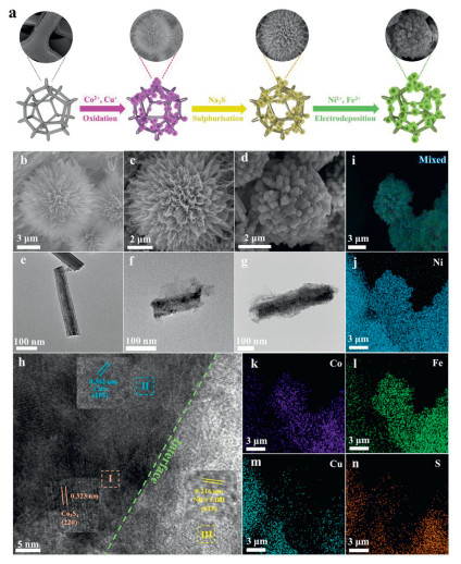
The 3D core-shell structur nanocoral sphere electrocatalyst has been successfully synthesized, as shown in Fig. 1a. To be specific, CoCu LDH nano sea urchins were grown in situ on NF through hydrothermal reaction in the presence of NH4F and urea, utilizing Co(NO3)2 and Cu(NO3)2 as the sources of Co and Cu. Subsequently, the product was sulfided (50 min) using sodium sulfide as the sulfur source to obtain Co3S4/CuS nanoflowers. As a comparison, products with sulphurisation times of 10 and 50 min were also prepared to explore the optimal sulphurisation time ratio. Finally, NiFe LDH nanosheets were encapsulated in Co3S4/CuS nanoflowers to generate 3D core-shell structure Co3S4/CuS@NiFe LDH nanocoral spheres by the electrodeposition process. Appropriate electrodeposition time will result in optimal interfacial interaction of Co3S4/CuS@NiFe LDH core-shell structure, which contributes to the enhancement of catalytic performance. Therefore, three electrocatalysts, Co3S4/CuS@NiFe LDH-1, Co3S4/CuS@NiFe LDH-2 and Co3S4/CuS@NiFe LDH-3, were synthesized by adjusting different electrodeposition times to investigate the optimal electrodeposition time.
Figure 1
Figure 1.
(a) Synthesis illustration. SEM images and TEM images of (b, e) CoCu LDH, (c, f) Co3S4/CuS and (d, g) Co3S4/CuS@NiFe LDH. (h) HRTEM image with selected magnified areas (Ⅰ, Ⅱ and Ⅲ) and (i-n) elemental mapping images of Co3S4/CuS@NiFe LDH.
The 3D nano sea urchins structure can be observed in Fig. 1b, indicating the CoCu LDH precursor was successfully grown in situ on NF. Fig. 1e shows that the nanowires constituting the 3D structure of CoCu LDH have smooth edges. For transmission electron microscopy (TEM) measurement, it is necessary to sonicate the product from NF to form a powder sample [33]. However, due to the prolonged and powerful ultrasonic treatment, the 3D structure of the product is broken down into 1D nanowires, and therefore, the TEM images display a 1D nanowire structure. The 3D nano sea urchins structure aids in generating active sites and accelerating gas release [34]. Therefore, further processing based on this can effectively improve the performance of electrocatalysts. After sulphurisation, Co3S4/CuS-2 nanowires aggregate into irregular sheet-like structures, and the structure of the catalyst changes from 3D nano sea urchins to 3D nanoflowers (Fig. 1c). The sheet-like structure contributes to the stability of the catalyst, while the heterostructure constructed between bimetallic sulphides forms abundant defects at the interface, which facilitates the generation of active sites [35,36]. Fig. 1f shows that the edges of Co3S4/CuS-2 nanowires become rough, which is caused by the sulphurisation reaction. On the other hand, the structures of the catalysts with sulphurisation times of 10 and 90 min are also transformed into 3D nanoflowers (Fig. S1a and b in Supporting information). However, the aggregation degree of nanowires in the structure of Co3S4/CuS-1 is relatively low, and a clear linear structure can be observed. In the structure of Co3S4/CuS-3, although a sheet-like structure is formed, the nanosheets are thicker and sparser compared to the nanosheets formed by Co3S4/CuS-2, which can lead to the active sites being partially masked and unfavorable release of the gases. Compared with Co3S4/CuS-2, the TEM images of Co3S4/CuS-1 and Co3S4/CuS-2 show no significant changes (Figs. S2a and b in Supporting information). The subsequent electrodeposition process results in the decomposition of the sheet-like structure in Co3S4/CuS-2 back into nanowires, and NiFe LDH nanosheets are encapsulated on the generated nanowires, ultimately forming 3D core-shell structured nanocoral spheres (Fig. 1d). By comparing the SEM images of Co3S4/CuS@NiFe LDH-1 and Co3S4/CuS@NiFe LDH-3 (Figs. S1c and d in Supporting information), it is indicated that the sheet-like structure in Co3S4/CuS breaks down more thoroughly with the increase of the electrodeposition time, resulting in the formation of finer and denser nanocorals. An overly dense structure can result in the active site being partially covered and is not conducive to gas release. The TEM images of the above three all display clear core-shell structures (Fig. 1g, Figs. S2c and d in Supporting information). In addition, the EDS (Fig. S3h in Supporting information) and elemental mapping images (Figs. 1i–n) of Co3S4/CuS@NiFe LDH reveal the presence of Co, Cu, S, Ni and Fe, confirming the successful synthesis of the Co3S4/CuS@NiFe LDH catalyst. Meanwhile, the HAADF image and STEM elemental mapping images further confirm the existence of core-shell structure (Figs. S3a–g in Supporting information).
HRTEM image is utilized to further investigate the composition and the interface of the core-shell structure [34]. A well-defined interface is seen between the bimetallic sulphides and NiFe LDH, as shown in Fig. 1h. It is evident that there exist lattice stripes in regions Ⅰ and Ⅱ within the interface, which are owned by the (220) plane of Co3S4 (0.323 nm) and the (102) plane of CuS (0.302 nm). Similarly, a lattice stripe on the (015) plane of NiFe LDH exists in region Ⅲ outside the interface (0.216 nm). The above phenomenon proves the existence of the core-shell structure.
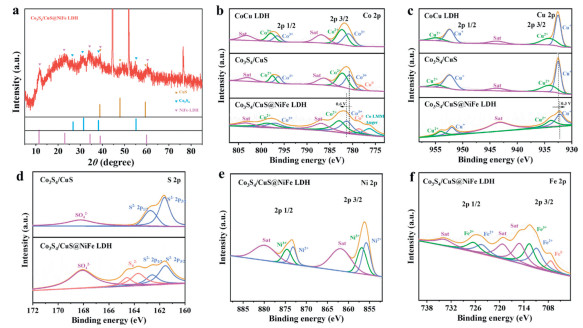
The crystal structure of the sample is analyzed using X-ray diffraction (XRD) [37]. To attenuate the effect of the high-intensity peaks of the NF on the test results, the sample was subjected to ultrasonic treatment and its powder state was tested by XRD. As is shown in Fig. 2a, the (220), (311), (400) and (440) planes of Co3S4 corresponded to diffraction peaks at 26.5°, 31.4°, 38.2° and 55.1°, respectively [38,39]. And the diffraction peaks at 2θ = 38.8°, 47.9° and 59.3° are attributed to the (105), (110) and (116) planes of CuS (PDF #06-0464) [40]. While the (003), (006), (012), (015) and (110) planes of NiFe LDH (PDF #40-0215) corresponded to intensive peaks at 11.6°, 23.4°, 34.5°, 38.8° and 59.9°, respectively [41]. Furthermore, Figs. S5a and b (Supporting information) [42,43] show the XRD analysis of samples grown in situ directly on NF. The peaks at 44.5°, 51.8° and 76.4° are vested in the (111), (200) and (220) planes of NF (PDF #07-0407), respectively [44]. The peaks of CoCu LDH at 43.5° and 74.3° are attributed to the (131) and (024) planes of Cu(OH)2 (PDF #13-0420), and the peak at 50.6° is owned by the (221) plane of CoO(OH) (PDF #02-0566).
Figure 2
Figure 2.
Physical characterizations of CoCu LDH, Co3S4/CuS and Co3S4/CuS@NiFe LDH: (a) XRD pattern, XPS spectra of (b) Co 2p, (c) Cu 2p, (d) S 2p, (e) Ni 2p and (f) Fe 2p.
The elemental valence states of materials are analyzed using X-ray photoelectron spectroscopy (XPS). For the Co 2p spectrum of Co3S4/CuS@NiFe LDH in Fig. 2b, the peaks located at 781.3, 797.0 eV and 782.8, 798.3 eV indicate the existence of Co3+ and Co2+, along with two satellite peaks (786.8 and 803.4 eV) [45,46]. A new peak at 776.3 eV also appears after electrodeposition, which corresponds to the Co LMM Auger. In addition, due to the strong reducibility of Na2S, a new peak related to Co0 appears in the spectrum [47]. The Co 2p peak position of Co3S4/CuS@NiFeLDH has shifted forward by 0.6 eV based on Co3S4/CuS, suggesting that the introduction of NiFe LDH optimizes the electronic interactions of Co with other metals and redistributes its electrons. Regarding the Cu 2p XPS spectrum of Co3S4/CuS@NiFe LDH in Fig. 2c, the two intensive peaks located at 932.2 and 952.0 eV evidence the existence of Cu+, whereas the two weaker peaks located at 933.8 and 954.0 eV are owned by Cu2+ [48]. Meanwhile, there is a satellite peak at 943.3 eV. Obviously, compared to the Cu 2p spectrum of Co3S4/CuS, the peak position of Cu sites shifted negatively, indicating that Cu obtained electrons after the electrodeposition step. In Fig. 2d, the S 2p XPS spectrum of Co3S4/CuS@NiFe LDH is reasonably deconvoluted. The peaks of S2− appear in the spectrum (161.6 and 162.6 eV), signaling the formation of metal-S bonds [49]. The peaks located at 168.1 is assigned to S—O bonds in SO42− [50]. The peaks located at 163.7 and 164.5 eV can be owned by polysulfides (Sn2−) produced during the electrodeposition process [51,52]. In Fig. 2e, four intensive peaks located at 855.8, 873.2, 856.8 and 874.6 eV are assigned to 2p3/2 and 2p1/2 of Ni2+ and Ni3+, and the peaks located at 861.9 and 879.9 eV have been proven to be satellite peaks of Ni [53]. The Fe 2p spectrum of Co3S4/CuS@NiFe LDH contains two sets of peaks at 710.9, 724.4 eV and 712.6, 726.4 eV attributed to Fe2+ and Fe3+, respectively (Fig. 2f) [54]. The peaks at 719.2 and 733.7 eV are owned by satellite peaks of Fe3+. Since the intensity of the satellite peak of Fe2+ at 729.5 is below the detection limit, only one satellite peak of Fe2+ (715.1 eV) is present in the spectrum [55]. Additionally, there is a peak related to Fe0 in the spectrum [56].
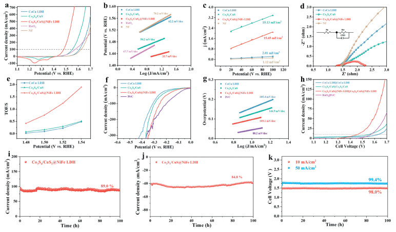
To avoid the interference of anodic peaks appearing during positive scanning, the polarization curves are gained by negative scanning [57]. First, the OER activities of Co3S4/CuS catalysts with different sulphurisation times are examined, and the optimal OER performance of Co3S4/CuS-2 can be clearly seen from Fig. S6a (Supporting information). Therefore, selectively using Co3S4/CuS-2 as a precursor catalyst for electrodeposition reaction will tremendously enhance the catalytic activity of Co3S4/CuS@NiFe LDH. The Co3S4/CuS@NiFe LDH exhibits unparalleled OER performance (η100 = 251 mV, η300 = 292 mV), which is much lower than NF (η100 = 395 mV, η300 = 450 mV), CoCu LDH (η100 = 380 mV, η300 = 433 mV), Co3S4/CuS (η100 = 321 mV, η300 = 376 mV) and RuO2 (η100 = 344 mV, η300 = 454 mV), as illustrated in Fig. 3a and Fig. S7 (Supporting information). This phenomenon suggests that the synergistic effect present in the Co3S4/CuS@NiFe LDH heterostructure optimizes the electronic structure and interfacial properties of the components within the catalyst, endowing the electrocatalysts with extraordinary intrinsic activity [58]. The above advantages also make Co3S4/CuS@NiFe LDH outperform the most OER catalysts (Table S1 in Supporting information). Furthermore, the OER activities of Co3S4/CuS@NiFe LDH with different electrodeposition times are also investigated, and Fig. S8a (Supporting information) shows that the sample with an electrodeposition time of 60 s exhibits the best catalytic activity. The reaction rate of the electrocatalyst can be explored by calculating the Tafel slope. As expected, the Co3S4/CuS@NiFe LDH displays the minimum Tafel slope (33.7 mV/dec) in Fig. 3b, which is much lower than NF (70.2 mV/dec), CoCu LDH (62.2 mV/dec), Co3S4/CuS (50.2 mV/dec) and RuO2 (67.7 mV/dec). This result illustrates that the Co3S4/CuS@NiFe LDH catalyst has fast reaction kinetics. Of course, the Tafel slopes of Co3S4/CuS-2 and Co3S4/CuS@NiFe LDH-2 remain the lowest for electrocatalysts with different sulphurisation times and different electrodeposition times (Figs. S6b and S8b in Supporting information).
The electrochemically active surface area (ECSA) reveals the active surface area of the catalyst in contact with the electrolyte during the electrochemical reaction, which is linearly related to the double-layer capacitance (Cdl) [59]. The Cdl value of Co3S4/CuS@NiFe LDH is 15.65 mF/cm2, and it is larger than NF (1.12 mF/cm2), CoCu LDH (2.01 mF/cm2) and Co3S4/CuS (15.13 mF/cm2), attesting that it has the utmost ECSA (Fig. 3c). In other words, the Co3S4/CuS@NiFe LDH heterostructure is favorable for providing more active sites under the same geometric area. Figs. S6c and S8c (Supporting information) show the Cdl values of Co3S4/CuS and Co3S4/CuS@NiFe LDH with different sulphurisation times and different electrodeposition times. The comparison results show that Co3S4/CuS-2 and Co3S4/CuS@NiFe LDH-2 have the utmost ECSA. Moreover, the LSV curve gained by normalizing the current density using the ECSA value is more representative of the intrinsic activity of the electrocatalyst [28]. Fig. S11 (Supporting information) indicates that Co3S4/CuS@NiFe LDH has higher intrinsic activity, which further confirms the superiority of core-shell heterostructure. Rapid charge transfer reflects outstanding catalytic kinetics [60]. The electron transfer rate of the electrocatalysts is evaluated by the EIS test. It can be seen from the Nyquist plots (Fig. 3d) that Co3S4/CuS@NiFe LDH has the smallest radius of semicircle, signaling that it possesses the fastest catalytic kinetics. The Co3S4/CuS substrate serves as a bridge for charge transfer between NF and NiFe LDH and provides favorable conductivity. Similarly, the charge transfer resistance of Co3S4/CuS-2 and Co3S4/CuS@NiFe LDH-2 is the smallest in the comparison of their respective sulphurisation times and electrodeposition times (Figs. S6d and S8d in Supporting information). The turn-over frequency (TOF) is an evaluation of the rate at which the electrocatalyst catalyzes the reaction, which reflects the intrinsic activity of the catalyst. As shown in Fig. 3e and Fig. S12 (Supporting information), the TOF values of Co3S4/CuS@NiFe LDH at different potentials were larger than those of CoCu LDH and Co3S4/CuS, indicating that Co3S4/CuS@NiFe LDH has more active sites.
Stability is a meaningful indicator for assessing the commercial application of electrocatalysts [61]. Therefore, multiple stability tests are employed to comprehensively evaluate the OER stability of Co3S4/CuS@NiFe LDH. Firstly, the stability of Co3S4/CuS@NiFe LDH is tested by i-t testing at 100 mA/cm2 (Fig. 3i). The remarkable stability of Co3S4/CuS@NiFe LDH is indicated by the 11% decrease in the current density after 100 h of testing. Subsequently, the stability of Co3S4/CuS@NiFe LDH is again evaluated by CP testing (Fig. S13a in Supporting information). The performance of the electrocatalyst remain almost consistent during long-term testing, further confirming the outstanding OER stability of Co3S4/CuS@NiFe LDH. In addition, Fig. S13b (Supporting information) shows that after 2000 CV cycles, the LSV curves of Co3S4/CuS@NiFe LDH basically coincide with its initial curve, which once again suggests that the catalyst has excellent stability. Based on the above three stability test results indicate that the electrodeposition of NiFe LDH on Co3S4/CuS substrate to form a core-shell structure utilizing the interface engineering strategy can improve the catalytic performance of the catalysts while NiFe LDH can also act as a protective shell to effectively inhibit the electrochemical corrosion of the catalysts at high current densities, thereby improving its catalytic stability [28].
Furthermore, SEM and XPS analyses were performed on Co3S4/CuS@NiFe LDH after the OER test. As shown in Fig. S14a (Supporting information), the overall morphology of the catalyst did not change significantly after the OER test, and the coral sphere structure was still retained, which confirms that Co3S4/CuS@NiFe LDH has high stability. After the test, the elemental valence states on the surface of the sample changed significantly, with a significant increase in the content of high-valence species of all metal elements, a result that indicates that all metal elements are oxidized during the OER process (Fig. S15 in Supporting information).
To reveal the effect of the introduction of NiFe LDH on the OER performance of the electrocatalysts, the OER mechanisms of different samples were further explored. The conventional adsorbate evolution mechanism (AEM) pathway consists of four synergistic proton-electron transfer processes involving the intermediate adsorption limitation of *OOH, while the lattice oxygen oxidation mechanism (LOM) pathway utilizes the involvement of lattice oxygen in the OER process, which achieves the direct coupling of O—O radicals and improves the OER activity of the catalyst. The LOM pathway exhibits a strong pH dependence due to its non-synergistic proton-electron transfer process [62]. Therefore, the OER performance of all samples was tested at different pH environments. Figs. S16a–c (Supporting information) show that the pH dependence of the catalysts gradually increases as the vulcanization and electrodeposition process proceeds, with Co3S4/CuS@NiFe LDH exhibiting the strongest pH dependence, a phenomenon that suggests that the catalyst tends to be more oriented towards the LOM pathway after the introduction of NiFe LDH. In addition, tetramethylammonium ions can specifically bind to negatively charged oxygenated species, thereby hindering the LOM pathway [63]. Therefore, 1 mol/L TMAOH was used instead of 1 mol/L KOH to evaluate the OER activity of the electrocatalysts employed. Fig. S16d (Supporting information) shows no significant change in the activity of CoCu LDH, indicating that its OER process follows the AEM pathway. On the contrary, the OER activity of Co3S4/CuS@NiFe LDH was significantly reduced, further confirming that Co3S4/CuS@NiFe LDH follows the LOM pathway during the OER process (Fig. S16f in Supporting information).
To evaluate the dual functionality of electrocatalysts, the HER performance of all samples is measured. Co3S4/CuS@NiFe LDH exhibits excellent HER activity (η100 = 254 mV), surpassing CoCu LDH (η100 = 311 mV) and Co3S4/CuS (η100 = 296 mV) in Fig. 3f and Fig. S17 (Supporting information). This performance is superior to most HER catalysts (Table S2 in Supporting information). Meanwhile, comparing the Tafel slopes of CoCu LDH (185.4 mV/dec), Co3S4/CuS (144.9 mV/dec) and Co3S4/CuS@NiFe LDH (113.8 mV/dec), it can be found that Co3S4/CuS@NiFe still possesses the smallest Tafel slope, suggesting that it possesses fast HER kinetics (Fig. 3g). The above phenomena signal that between Co3S4, CuS and NiFe LDH generates strong interface electronic interactions, accelerating charge transfer and leading to rapid HER kinetics. Besides, the HER stability of the product is further improved by the modification of NiFe LDH. The only slight decrease in the potential of Co3S4/CuS@NiFe LDH during the i-t testing for 100 h demonstrates that the NiFe LDH protective shell strengthens the HER stability (Fig. 3j). Fig. S14b (Supporting information) shows the SEM image of Co3S4/CuS@NiFe LDH after the HER test. The overall morphology of the catalyst is still preserved.
Considering the distinguished OER and HER performances of the material, Co3S4/CuS@NiFe LDH is used for OWS testing. Fig. 3h and Fig. S18 (Supporting information) signal that Co3S4/CuS@NiFe LDH exhibits incomparable OWS activity, requiring only 1.46 V for Co3S4/CuS@NiFe LDH||Co3S4/CuS@NiFe LDH at 10 mA/cm2, outdistancing that of CoCu LDH||CoCu LDH (1.63 V), Co3S4/CuS||Co3S4/CuS (1.55 V) and RuO2/Pt/C||RuO2/Pt/C (1.57 V). Meanwhile, Co3S4/CuS@NiFe LDH||Co3S4/CuS@NiFe LDH can maintain impressive performance even at high currents. Additionally, the stability of the bifunctional electrocatalyst Co3S4/CuS@NiFe LDH is tested using CP testing. Fig. 3k shows that the cell voltage of Co3S4/CuS@NiFe LDH||Co3S4/CuS@NiFe LDH remains almost constant over 100 h, indicating its remarkable stability.
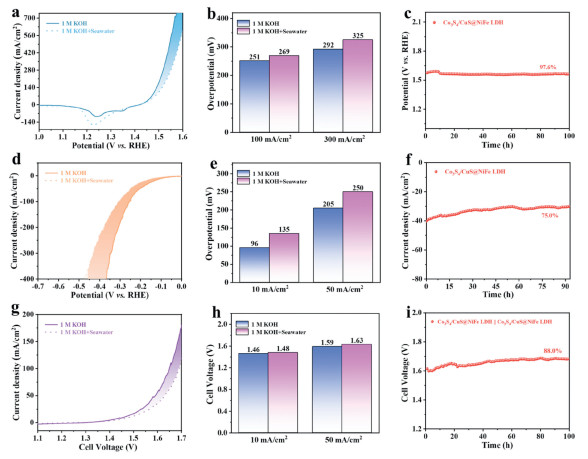
The performance of Co3S4/CuS@NiFe LDH electrocatalysts is further evaluated in seawater to meet the demands of industrial applications [64]. In Figs. 4a and b, the OER performance of Co3S4/CuS@NiFe LDH in alkaline seawater is almost the same at low current densities compared to the OER test results in 1 mol/L KOH. There is only a difference of 18 and 33 mV between the two at 100 and 300 mA/cm2. Furthermore, the stability testing manifests that the OER performance of Co3S4/CuS@NiFe LDH is essentially unchanged for 100 h, indicating that natural alkaline seawater has little effect on the OER performance of the electrocatalyst (Fig. 4c). Figs. 4d and e show that the HER performance of Co3S4/CuS@NiFe LDH is slightly degraded owing to the presence of Cl− and potential toxicity from other microorganisms in seawater [24]. And Co3S4/CuS@NiFe LDH still displays impressive performance in the stability test of HER at 90 h (Fig. 4f).
Figure 4
Figure 4.
Catalytic performance of Co3S4/CuS@NiFe LDH in natural alkaline seawater for OER, HER and OWS: (a, d, g) LSV curves, (b, e) overpotential comparison charts, (h) cell voltage comparison chart and (c, f, i) stability testing curves.
To further investigate the performance of Co3S4/CuS@NiFe LDH in alkaline seawater for overall seawater splitting, the catalyst is used for overall seawater splitting in alkaline seawater. Co3S4/CuS@NiFe LDH also exhibits extraordinary overall seawater splitting performance (V10 = 1.48 V, V50 = 1.63 V) (Figs. 4g and h). The catalytic activity of Co3S4/CuS@NiFe LDH remains basically unchanged in the long-term stability testing at 10 mA/cm2 in Fig. 4i. Additionally, the corrosion curves further confirm the excellent catalytic performance and stability of Co3S4/CuS@NiFe LDH in alkaline seawater (Fig. S19 in Supporting information). Compared with the corrosion current values of CoCu LDH and Co3S4/CuS, Co3S4/CuS@NiFe LDH shows the lowest corrosion current density (Icorr = 0.03648 mA/cm2), indicating that the introduction of NiFe LDH is beneficial for mitigating the corrosion of the material in alkaline seawater.
In summary, a 3D core-shell structure Co3S4/CuS@NiFe LDH nanocoral spheres electrocatalyst was successfully synthesized using a straightforward hydrothermal and electrodeposition process. The interfacial synergistic effect among the three components of Co3S4, CuS and NiFe LDH enhances the electronic interactions, thereby accelerating the charge transfer during the electrochemical process. The doping of NiFe LDH significantly activates the lattice oxygen in the hydroxyl oxides, leading to a shift of the OER process from the AEM pathway to the LOM pathway, which improves the intrinsic activity of the catalyst. In alkaline solution, Co3S4/CuS@NiFe LDH exhibits remarkable performances for OER (η100 = 251 mV) and HER (η100 = 254 mV) and maintaining stability over a period of 100 h. Additionally, Co3S4/CuS@NiFe LDH also exhibits excellent catalytic activity in natural alkaline seawater due to the protective shell strategy of NiFe LDH that significantly improves the corrosion resistance of the electrocatalyst. Although the catalytic performance of Co3S4/CuS@NiFe LDH shows a slight degradation for the OER, HER and OWS processes, an excellent stability of 100 h is maintained. This work broadens the framework for designing efficient and stable bifunctional catalysts using interface engineering strategies and even demonstrates extraordinary application potential in the field of overall seawater splitting.
Declaration of competing interest
The authors declare that they have no known competing financial interests or personal relationships that could have appeared to influence the work reported in this paper.
CRediT authorship contribution statement
Jun Yu: Writing – original draft. Yangping Zhang: Conceptualization. Nannan Zhang: Data curation. Jie Li: Conceptualization. Huiyu Sun: Methodology. Xinyu Gu: Data curation. Changqing Ye: Supervision. Tianpeng Liu: Data curation. Yukou Du: Writing – review & editing.
Acknowledgment
This work was supported by the National Natural Science Foundation of China (No. 52274304).
Supplementary materials
Supplementary material associated with this article can be found, in the online version, at doi:10.1016/j.cclet.2025.110830.
[1]
J. Cao, D. Zhang, B. Ren, P. Song, W. Xu, Chin. Chem. Lett. 35 (2024) 109863. doi: 10.1016/j.cclet.2024.109863
[2]
J. Li, Y. Zhang, M. Hu, C. Ye, Y. Du, ACS Appl. Mater. Interfaces 16 (2024) 48846–48853. doi: 10.1021/acsami.4c11658
Figure 1
(a) Synthesis illustration. SEM images and TEM images of (b, e) CoCu LDH, (c, f) Co3S4/CuS and (d, g) Co3S4/CuS@NiFe LDH. (h) HRTEM image with selected magnified areas (Ⅰ, Ⅱ and Ⅲ) and (i-n) elemental mapping images of Co3S4/CuS@NiFe LDH.
Figure 2
Physical characterizations of CoCu LDH, Co3S4/CuS and Co3S4/CuS@NiFe LDH: (a) XRD pattern, XPS spectra of (b) Co 2p, (c) Cu 2p, (d) S 2p, (e) Ni 2p and (f) Fe 2p.

 DownLoad:

 下载:
下载:


