Received Date:
03 September 2024 Accepted Date:
07 November 2024 Revised Date:
02 October 2024 Available Online:
15 February 2026
Abstract:
The high voltage of Li||LiCoO2 battery can increase the energy density. However, the cycling performance associated with cathode structural stability remains challenging. To address this question, we proposed an electrolyte strategy for improving the performance of 4.6 V Li||LiCoO2 battery by using trimethylsilyl isocyanate (TMIS) as electrolyte additive. The trimethylsilyl group of TMIS can trap HF while the isocyanate group brings polyamide components to the CEI and the SEI. By the synergistic action, the Co3+ dissolution problem of the LiCoO2 cathode was effectively curbed. Furthermore, TMIS regulates the construction of anion-dominated LiF-rich SEI by influencing the solvation structure of Li+. As expected, the 4.6 V Li||LiCoO2 battery with TMIS retains 77.9% initial capacity after 200 cycles at 0.5 C.
It is well-accepted that broadening electrochemical window will increase the lithium usage rate of cathode and energy density of battery [1,2]. However, over-high operating voltage will bring problems of cathode structure pulverization, transition metal ions dissolution, excessive electrolyte decomposition, which will result in short cycling life and low coulombic efficiency (CE) of batteries. In practical application, electrochemical window of batteries and lithium usage rate of cathodes are always limited to ensuring the cycling life [3-5]. For example, LiCoO2 (LCO), with a theoretical capacity of 274 mAh/g, can only deliver a limited capacity of about 130 mAh/g with a cut of voltage of 4.2 V (vs. Li+/Li) [6]. To improve the lithium utilization rate of LCO, the cut off voltage should be raised to 4.45 V (vs. Li+/Li) or even higher. Unfortunately, with the high operating voltage, the capacity of LCO based battery decays rapidly [7,8].
The high-quality electrolytes can solve the above problems in significant measure by constructing protective electrolyte-electrode interfaces (EEIs) on electrode surfaces [9,10]. At present, the most popular liquid electrolyte is LiPF6 as the lithium salt dissolved in carbonate solvents [11-13]. However, the thermal decomposition and hydrolysis reactions of LiPF6 is intensified at high operating voltage, and the strong corrosive HF generated erodes the interphases on the surfaces of both LCO cathode and Li anode, leading to the consumption of electrolyte and the dissolution of Co3+ [14-16]. Silicon-based additives with Si-O or Si-N bonds have the effect of eliminating HF and PF5, that can effectively protect the electrodes [17].
Herein, we chose trimethylsilyl isocyanate (TMIS) as the additive to achieve the goals of suppressing transition metal ions dissolution and constructing high quality EEIs with high inorganic component content. The additive molecule consists of two parts, the isocyanic acid group and the trimethylsilyl group. On the one hand, the central Si of the trimethylsilyl is electrophilic, which can trap the F atom in HF to generate fluoro-(trimethyl)silane (FTMS), and reduce the damage of HF to the LCO and CEI structures. At the same time, N atom with a lone pair of electrons can act as an electron donor to coordinate with strong Lewis acid PF5 that accepts electrons, mitigating the hydrolysis reaction of PF5 and the production of HF. On the other hand, TMIS can preferentially decompose on the electrodes surface before solvent molecules to form polyamide components, which can promote the transport of Li+ and inhibit the Co leaching. Finally, the O of the isocyanate group with two lone pair electrons has great electronegativity, which allows Li+ to coordinate with TMIS. This coordination regulates the solvated sheath structure of Li+. After the addition of TMIS, the anion content in the solvation group of Li+ increased, and the anion-dominated inner Helmholtz plane (IHP) was realized, which could promote the decomposition of anions at the Li anode to form a LiF-rich SEI. These favorable factors allow us to obtain a Li||LCO battery with stable cycle life and high CE at 4.6 V high voltage. The Li||LCO cell retains an initial capacity of 77.9% and a high CE after 200 cycles at a current density of 0.5 C.
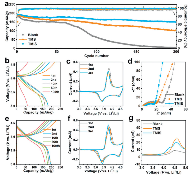
The Li||LCO battery was assembled with different silane-based additives to verify their functions. As shown in Fig. S1a (Supporting information), when the content of TMIS additive in electrolyte increased from 0.2 wt% to 0.5 wt%, the initial discharge capacity was significantly increased from 181.3 mAh/g to 193.7 mAh/g, indicating the improvement effect of TMIS on the Li||LCO battery performance. However, the amount of additive is restricted, when the mass ratio reaches to 1.0 wt%, the capacity drops rapidly to 159.1 mAh/g. Because the addition of additive will increase the viscosity of the electrolyte and lead to a lower capacity, which is further confirmed by the EIS test in Fig. S1b (Supporting information). Therefore, the optimal addition of TMIS additive is 0.5 wt%. The discussion of the mechanism of different contents of TMIS has been added to the manuscript. In Fig. 1a, the battery with blank electrolyte shows an initial discharge capacity of 180.2 mAh/g. After about 60 cycles, its discharge capacity decays rapidly. After 150 cycles, almost all the discharge capacity fades. With the rapid capacity decay process, the CEs of this battery become unstable. It suggests the inferior interphase structure of LCO cathode. By contrary, with silane-based additives, the batteries show better cycling performances. Especially the one with TMIS additive, it shows a high capacity of 149.8 mAh/g after 200 cycles, with high CEs. The initial coulomb efficiencies of Li||LCO batteries using blank electrolyte, the electrolyte with TMS and the electrolyte with TMIS are 81.86%, 66.45% and 84.23%, respectively. The charge-discharge profiles and CV curves of various Li||LCO batteries shown in Figs. 1b, c, e, f and Fig. S2 (Supporting information). There exist charge plateaus at about 4.10 and 4.55 V, discharge plateaus at 3.85 and 4.45 V (vs. Li+/Li). The couple at high voltage represents the phase transition of H1 to H1–3, which may destroy the LCO structure [18-20]. After 100 cycles, the battery assembled with blank electrolyte shows a large voltage polarization, meaning the formation of electrochemical inactive phase and inferior CEI structure. The EIS graphs of different batteries after 10 cycles are shown in Fig. 1d. The batteries with TMS and TMIS additives shows small interface impedance. By contrast, the one with blank electrolyte delivers the largest interface impedance of about 30 ohms. The LSV results of blank electrolyte, TMS and TMIS modified electrolytes are shown in Fig. 1g. Compared with blank electrolyte, the modified electrolytes show lower oxidation decomposition potential. This is because the additives are easily oxidized, meaning they participate in the formation of CEI. Besides, due to the bad storability, the TIS modified electrolyte only shows unsatisfying electrochemical performance (Fig. S3 in Supporting information). Therefore, we do not discuss this additive in this work.
Figure 1
Figure 1.
Electrochemical performance of Li||LCO batteries with different electrolytes. (a) Cycling performance for Li||LCO batteries with blank electrolyte, TMS- and TMIS-contained electrolytes. Charge-discharge curves and cyclic voltammetry (CV) curves for the batteries with (b, c) blank and (e, f) TMIS-contained electrolyte. (d) EIS curves of different Li||LCO batteries after 10 cycles. (g) Linear sweep voltammetry (LSV) curves of stainless-steel sheet symmetrical cells with different electrolyte systems. The voltage range of galvanostatic charge-discharge tests is 3–4.6 V (vs. Li+/Li), and the rate is 0.5 C (1 C = 200 mA/g). The scan rate of CV and LSV tests are 0.2 and 2 mV/s, respectively.
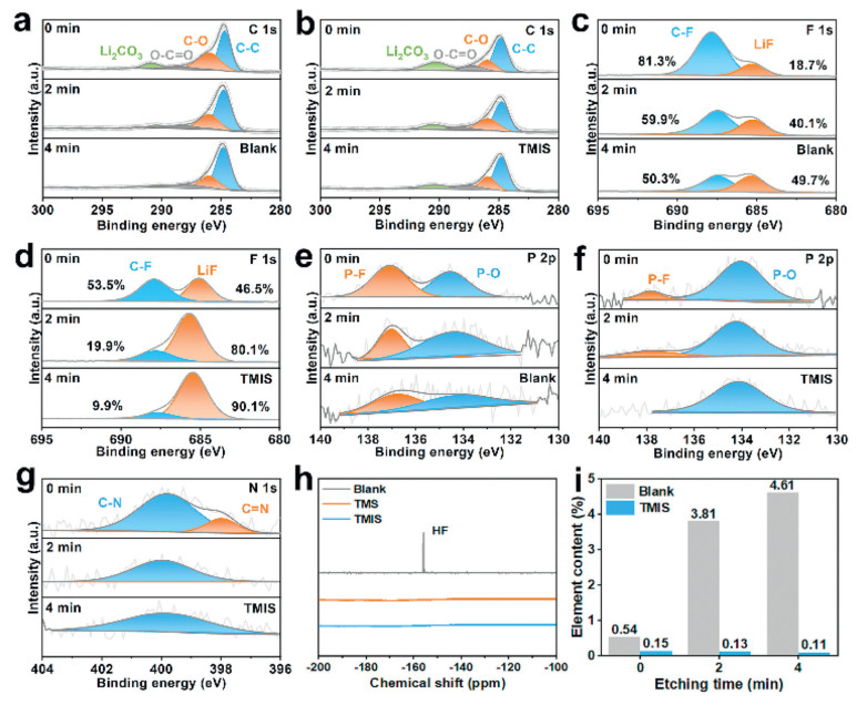
Etching X-ray photoelectron spectroscopy (XPS) results of CEI formed in different electrolyte systems were shown in Fig. 2, Figs. S4 and S5 (Supporitng information). In short, all the formed CEIs have two kinds of species: organic species (including ROLi, ROCOOLi, RCFx, and polycarbonate, R is alkyl group) and inorganic species (including LiF, Li2O, Li2CO3, and a little cobaltous oxide) [21,22]. Whereas, the CEI obtained in the presence of isocyanate-based silane additive has a lower percentage of C than that in the blank electrolyte, indicating less organic species produced from the solvent decomposition. As shown in Figs. 2a-c, formed in blank electrolyte, the CEI showed the low content of LiF and Li2CO3. In contrast, the addition of TMIS resulted in a higher content of Li2CO3 in the CEI, providing passages for Li+ through the CEI. Meanwhile, the CEI obtained from the electrolyte containing the additive showed a stronger LiF peak (Fig. 2d) especially in the inner layer. From this, it can be concluded that the addition of TMIS additive can increase the inorganic content of CEI. It is well known that high inorganic concentration can improve the quality of CEI. Especially the LiF in CEI, as a strong insulator, can effectively inhibit the continuous side reactions between the electrolyte and the cathode. In addition, as can be seen from the P 2p spectrum in Fig. 2e, the CEI formed by the blank electrolyte contained comparable P-F and P-O species. By contrast, the CEI with TMIS added had more P-O species and few P-F species, which can be explained by the Si 2p spectra of CEI formed by the TMIS additive. As shown in Fig. S4, the TMIS-modified CEI had Si-F species in addition to Si-C and SiO2 species. The electrophilic central Si of the trimethylsily can trap F- in both the electrolyte and CEI and form fluoro(trimethyl)silane (FTMS) [23,24]. In addition, the N atom of the isocyanate group has two lone pairs of electrons, which is alkaline, and can coordinate with the electron-accepting Lewis acid PF5, reducing the hydrolysis reaction of PF5. These properties give TMIS the ability to remove HF impurities and convert PF5. The 19F NMR results shown in Fig. 2h demonstrated its ability to eliminate HF, which helps to protect the CEI and crystal structure of the LCO cathode [25,26]. In addition, the -NCO group of the TMIS additive can undergo electrochemical polymerization on the LCO surface to form polyamide components (Fig. 2g) [27]. The polymerization products contribute to the formation of a dense and stable CEI that protects the cathode material from erosion. Under the joint action of the two functional groups of TMIS, the structure of LCO is effectively protected. As shown in Fig. S5, the M-O peak at 529 eV represented that the serious Co dissolution in the blank electrolyte, which could lead to the degradation of the LCO cathode crystal structure. However, the M-O peak in XPS after the addition of TMIS was nearly vanished, indicating the inhibited Co dissolution. Fig. 2i showed the Co content in CEI formed by blank electrolyte and TMIS modified electrolyte at different etch depths. It can be seen that the dissolution of Co was significantly inhibited by the addition of TMIS. The above experimental results showed that the TMIS-induced CEI significantly alleviates the decomposition of the electrolyte and the degradation of the cathode structure under a high voltage, thereby avoiding the rapid decline of capacity and improving the electrochemical stability of the high-voltage battery.
Figure 2
Figure 2.
Chemical component analysis of CEI after 10 cycles. Etching XPS results of C 1s, F 1s and P 2p spectrum for CEI formed in (a, c, e) blank electrolyte, and (b, d, f) TMIS modified electrolyte. (g) N 1s spectrum for CEI formed with TMIS additive. (h) 19F NMR spectra of blank and modified electrolyte with addition of deionized water (5%, volume rate) and stored at 60 ℃ for 12 h (i) Co element content of CEI formed in blank and TMIS modified electrolyte.
To observe the morphology of formed CEI and cycled LCO cathode, SEM characterizations were carried out. In Figs. 3a and b, cracks can be observed on the LCO particles tested in the blank electrolyte and the TMS modified electrolyte. Transition metal ion dissolution leads to irreversible phase transition of LCO, resulting in fracture [28,29]. With the addition of TMIS additive, the Co dissolution is effectively suppressed. Thus, the LCO particles can maintain unbroken morphology. As shown in Fig. 3c, affected by TMIS additive, squama-like CEIs formed without crack on LCO cathode. This is the one of the reasons why the battery with TMIS has an outstanding capacity retention rate.
Figure 3
Figure 3.
Scanning electron microscope (SEM) images for cathode after 10 cycles of galvanostatic tests in different electrolyte systems: (a) blank electrolyte, (b) TMS and (c) TMIS modified electrolytes. Transmission electron microscopy (TEM) images of CEI formed in different electrolytes: (d) blank electrolyte, (e) TMS and (f) TMIS modified electrolytes. High resolution TEM image and magnified images of marked area for LCO cathode cycled in (g, h) blank electrolyte, (i, j) TMIS modified electrolyte (after 200 cycles, 0.5 C). High resolution TEM image and magnified images of marked area for CEI formed in (k) blank electrolyte, (l-n) TMIS modified electrolyte.
The CEI thickness is characterized by TEM. As shown in Fig. 3d, cycled in blank electrolyte, the formed CEI has an uneven thickness, which distributes in a range of 40-65 nm. Too thick CEI means too much electrolyte consuming and low CE. With the addition of TMS and TMIS additive, the CEI thickness decrease (Figs. 3e and f). Especially for CEI formed with TMIS additive, it delivers a thin and uniform thickness of 25 nm. The quality of CEI has a large impact on the crystal structure of cycled LCO cathode. As shown in Fig. 3g, after a long cycling test in blank electrolyte, the layer structure of LCO cathode dispersed. As can be seen from Fig. 3h, the emerged crystal phase has a lattice distance of 2.44, corresponding to (311) plane of Co3O4 phase (Fd-3m, PDF #74–2120). Both the crystal structure rearrangement at high voltage and Co ion dissolution are attributed to the formation of Co3O4 phase with worse electrochemical performance [30,31]. By contrast, cycled with TMIS additive in the same condition, the layer structure of LCO cathode is reserved. As shown in Figs. 3i and j, the clear layer structure with lattice distance of 4.68 Å can be observed, corresponding to (003) plane of LiCoO2 phase (R-3m, PDF #77–1370). At last, the inorganic species in CEI also be characterized by TEM. As shown in Fig. 3k, the CEI formed in blank electrolyte possesses a low crystallinity without any crystal plane can be observed. By contrast, as shown in Figs. 3l-n, the one formed with TMIS additive shows a high crystallinity, for that crystal planes distribute in all the region of CEI. In the region Ⅰ and Ⅱ, the dominant crystal phase is LiF ((200) plane, Fm-3m space group, PDF #78-1217) and Li2CO3 ((1‾12) plane, C2/c space group, PDF #83-1454) phases, agreeing with XPS results.
To further explain the internal mechanism of TMIS, the density functional theory (DFT) calculation and molecular dynamics (MD) simulation were carried out. As can be seen from Fig. 4a, only the TMIS molecule has the higher HOMO level than those of both the two solvent molecules. It means that TMIS additive can be oxidative decomposed before EC and EMC molecules, to suppress too much solvent consumption. It can not only increase the inorganic species content of CEI, but also increase the CE of high voltage Li||LCO battery. Meanwhile, TMIS possesses the lowest LUMO value of the molecule, so it can be preferentially reduced and decomposed on the surface of the Li anode. The isocyanate group of TMIS would polymerize on the surface of the two electrodes and form polyamide components, which can promote the migration of Li+ in the interfacial films, and passivate the surface to form stable interface films [32,33]. Because of the electronegativity of O in isocyanyl group, Li+ can coordinate with TMIS molecule (Fig. 4b). As shown in Figs. 4c-e, the original Li+ solvation sheath structure is changed by the entering of TMIS additive. It is worth noting that TMIS increases the coordination of anions with Li+, which helps to increase the number of anions in the double electric layer on the surface of the Li anode, generating anion-dominated LiF-rich SEI. The conclusions of calculate agree well with the XPS results. For the nonpolar structure of TMS molecule, this additive cannot coordinate with Li+ (Fig. S6 in Supporting information). Therefore, it can hardly regulate the Li+ solvation sheath structure.
Figure 4
Figure 4.
Theoretical prediction of isocyanyl silane-based additives. (a) The highest occupied molecular orbital (HOMO) and lowest unoccupied molecular orbital LUMO levels of the additives and electrolyte solvents. Molecular dynamics (MD) simulation results of blank electrolyte and isocyanyl silane-based additive modified electrolyte: Cumulative coordination number (n(r)) of (b) Li+ with TMIS additive molecule, (c) Li+ with O (EC molecule), (d) Li+ with O (EMC molecule), and (e) Li+ with P (PF6-).
Lithium anode is another electrode for the Li||LCO battery. The silane-based additives can also regulate the lithium electrochemical depositing/stripping behavior. As can be seen from Figs. S7 and S8 (Supporting information), with TMIS, the symmetrical Li||Li cell shows better cycling life at different current density. The SEM image can also prove the growth of lithium dendrites is suppressed. There are two reasons for this improvement. Firstly, the silane-based additives can increase the wettability of electrolyte to separator (Fig. S9 in Supporting information). According to our previous work, this can regulate and control the Li+ flow [34]. Secondly, as displayed in Fig. S10 (Supporting information), The SEI formed by the modified electrolyte is rich in the decomposition product LiF of PF6-, which is conducive to the uniform deposition of Li. In addition, the addition of TMIS brings polar amide groups (polyamide components), which is conducive to the transport of Li+. These two factors are helpful to suppress lithium dendrite growth. Therefore, TMIS can construct high quality interphase on both cathode and anode surfaces meanwhile.
In conclusion, we have successfully proposed an electrolyte strategy to improve the performance of 4.6 V Li||LCO battery with multifunctional additive. Firstly, the electrophilic central Si of TMIS additive can capture HF, and the N in the isocyanate group can alleviate the hydrolysis of PF5, reducing the HF attack to LCO and Li anode at high voltage. Secondly, TMIS with high chemical activity forms polyamide components on the surface of the electrodes, which are conducive to the transport of Li+. Based on the characterization results, the morphology brokening and Co dissolution of LCO cathode are suppressed. The cathode protection and excellent CEI structure enable 4.6 V Li||LCO battery to retain 77.9% of the initial capacity after 200 cycles at a current density of 0.5 C with high CEs. This work provides new insights into the multifunctional additive design strategy for high voltage batteries.
Declaration of competing interest
We, herein, declare that there is not any conflict of interest.
CRediT authorship contribution statement
Xi Tang: Writing – original draft. Shihan Qi: Writing – original draft. Jian He: Validation. Jiandong Liu: Validation. Xiu Li: Writing – review & editing. Jiu Lin: Writing – review & editing. Abdullah N. Alodhayb: Writing – review & editing. Lihua Wang: Investigation. Jianmin Ma: Writing – review & editing.
Acknowledgments
The project was supported by the National Natural Science Foundation of China (Nos. U21A20311 and 52400163).
Supplementary materials
Supplementary material associated with this article can be found, in the online version, at doi:10.1016/j.cclet.2024.110622.
[1]
S. Mao, Q. Wu, F. Ma, et al., Chem. Commun. 57 (2021) 840–858. doi: 10.1039/d0cc06849g
[2]
P.K. Nayak, L. Yang, W. Brehm, et al., Angew. Chem. Int. Ed. 57 (2018) 102–120. doi: 10.1002/anie.201703772
J. Huang, J. Liu, J. He, et al., Angew. Chem. Int. Ed. 60 (2021) 20717–20722. doi: 10.1002/anie.202107957
Figure 1
Electrochemical performance of Li||LCO batteries with different electrolytes. (a) Cycling performance for Li||LCO batteries with blank electrolyte, TMS- and TMIS-contained electrolytes. Charge-discharge curves and cyclic voltammetry (CV) curves for the batteries with (b, c) blank and (e, f) TMIS-contained electrolyte. (d) EIS curves of different Li||LCO batteries after 10 cycles. (g) Linear sweep voltammetry (LSV) curves of stainless-steel sheet symmetrical cells with different electrolyte systems. The voltage range of galvanostatic charge-discharge tests is 3–4.6 V (vs. Li+/Li), and the rate is 0.5 C (1 C = 200 mA/g). The scan rate of CV and LSV tests are 0.2 and 2 mV/s, respectively.
Figure 2
Chemical component analysis of CEI after 10 cycles. Etching XPS results of C 1s, F 1s and P 2p spectrum for CEI formed in (a, c, e) blank electrolyte, and (b, d, f) TMIS modified electrolyte. (g) N 1s spectrum for CEI formed with TMIS additive. (h) 19F NMR spectra of blank and modified electrolyte with addition of deionized water (5%, volume rate) and stored at 60 ℃ for 12 h (i) Co element content of CEI formed in blank and TMIS modified electrolyte.
Figure 3
Scanning electron microscope (SEM) images for cathode after 10 cycles of galvanostatic tests in different electrolyte systems: (a) blank electrolyte, (b) TMS and (c) TMIS modified electrolytes. Transmission electron microscopy (TEM) images of CEI formed in different electrolytes: (d) blank electrolyte, (e) TMS and (f) TMIS modified electrolytes. High resolution TEM image and magnified images of marked area for LCO cathode cycled in (g, h) blank electrolyte, (i, j) TMIS modified electrolyte (after 200 cycles, 0.5 C). High resolution TEM image and magnified images of marked area for CEI formed in (k) blank electrolyte, (l-n) TMIS modified electrolyte.
Figure 4
Theoretical prediction of isocyanyl silane-based additives. (a) The highest occupied molecular orbital (HOMO) and lowest unoccupied molecular orbital LUMO levels of the additives and electrolyte solvents. Molecular dynamics (MD) simulation results of blank electrolyte and isocyanyl silane-based additive modified electrolyte: Cumulative coordination number (n(r)) of (b) Li+ with TMIS additive molecule, (c) Li+ with O (EC molecule), (d) Li+ with O (EMC molecule), and (e) Li+ with P (PF6-).

 DownLoad:


 下载:
下载:


