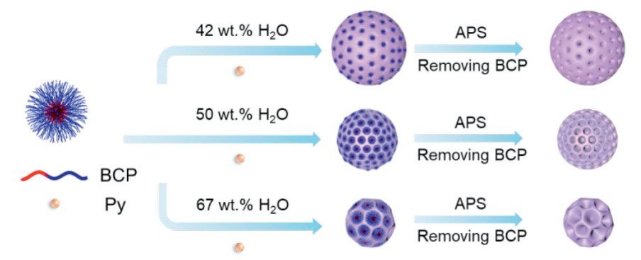
Figure 1.
Schematic illustration of monodisperse hierarchical porous PPy nanospheres.
Mesoporous N-rich carbon nanospheres regulating high dispersion of red phosphorus for sodium-ion batteries
Hongyi Zhang , Wenda Li , Hao Luo , Lingyan Huang , Facai Wei , Shanzhe Ke , Liguo Ma , Chengbin Jing , Jiangong Cheng , Shaohua Liu

Sodium-ion batteries (SIBs) have garnered significant attention in recent years owing to the abundant sodium resource and comparable electrochemical performance to that of lithium-ion batteries [1-3]. Nevertheless, there are still some critical issues that need to be addressed before the commercialization of SIBs [4-8]. Especially, the development of viable anode materials remains the main scientific obstacle due to their low sodium storage capacity and rapid decay for a competitive SIB technology [9-11]. Many proposals have been made to develop anode materials (e.g., hard carbon, metal alloys and phosphides) for high-performance SIBs [12-14]. Recently, red-phosphorus (RP) delivers a remarkable theoretical specific capacity of 2596 mAh/g, low cost and a safe working potential of 0.45 V versus Na/Na+, thus garnering significant attention as a potential anode material [15,16]. Nevertheless, the stress deformation and interface passivation during sodiation/desodiation of RP-based anodes would lead to electrical isolation and pulverization of active materials as well as drastic capacity fading, which impedes its rapid development [17-19].
To tackle these barriers, the strategies of decreasing the particle size and designing conductive configurations for RP are proposed to accommodate the significant volume-expansion-induced stress as well as boost the ionic/electrical conductivity. An efficient approach is to integrate RP with carbon-based conductive matrixes through vaporization-condensation or solution impregnation methods [20,21]. It is noted that the carbon materials could cooperatively enhance the electronic conductivity and accommodate the volume expansion during cycling [22,23]. However, the efficient dispersion of red phosphorus in high-conductive material through vaporization condensation is still limited [24]. Therefore, there is an urgent requirement to engineer advanced carbon hosts with desired architectures that can not only guarantee a high loading amount of RP but also simultaneously encapsulate RP within them to effectively accommodate the volumetric changes of RP during cycling [25].
In this work, we first developed a monomicelle-directed assembly strategy to fabricate polypyrrole-derived N-doped mesoporous carbon nanospheres (N-MCNs) with precisely controllable pore sizes and nanoarchitectures. Monomicelle formed by the self-assembly of polystyrene-block-poly(ethylene oxide) (PS-b-PEO) was used as an assembly unit, which could subsequently attract pyrrole (Py) precursor through hydrogen bond and then co-assemble into a secondary assembly. Driven by the polymerization process and aggregation effect of the secondary assemblies, the co-assemblies formed a uniform spherical micellar composite structure (PPy@PS-b-PEO). The derived N-MCNs have a porous micro/nanostructure with a high specific surface area (315 m2/g) and pore volume (0.63 cm3/g) obtained after extraction and carbonization. The resulting N-MCNs@RP composite owning plenty of space for loading RP can offer the strong adsorption for RP and form a P-C bond, which enhances the dispersion and electronic properties of RP. The results of theoretical simulations indicated that pyridine N atoms in the carbon framework can contribute to the comprehensive regulation of red phosphorus adsorption, enhancing electrical conductivity. Complementary characterizations clearly verified the high reversibility of sodiation/desodiation and robust interfacial/structural integrity of the N-MCNs@RP composite during cycling, which together delivered a discharge capacity of 856 mAh/g at a current density of 1.0 A/g with long cycle stability (capacity retention over 75%) after 1000 cycles.
The PPy nanospheres with different pore sizes can be control synthesized by a universal monomicelle-directed assembly approach taking PS-b-PEO as a template (Fig. 1) [26-29]. The adaptive block copolymer (BCP) synthesized were measured by nuclear magnetic resonance (NMR), which was labeled as PS66-b-PEO45 (Fig. S1 in Supporting information). Through gel permeation chromatography (GPC), a single spike appeared to exhibit an even distribution of molecular weight (Fig. S2 in Supporting information). Monodisperse spherical micelles with hydrophobic cores and hydrophilic crowns were formed because of hydrophilic and hydrophobic interaction in the tetrahydrofuran/ethanol/H2O mixture solution. After stirring constantly and adding pyrrole as monomers, pyrrole adsorbed on the surface of spherical micelles in order to co-assemble. Driven by polymerization caused by an oxidizing agent, the co-assembly of micelles and pyrrole stacked tightly from the dispersion so that the complex construction of spherical PPy@PS-b-PEO micelles was evolved with pore canals exposed by centrifugal subside. Notably, the aggregation effect of the co-assemblies was the key to this strategy. The concentration of micelles and co-assemblies changed by importing different volumes of water after micelles appeared. The lower the concentration of micelles was with the oxidizing agent applied, the less likely molecules of pyrrole were to cross-link and polymerize. Therefore, the fabrication and morphology adjustment of 0D mesoporous PPy could be realized according to the number of co-assemblies and the extent of interaction.
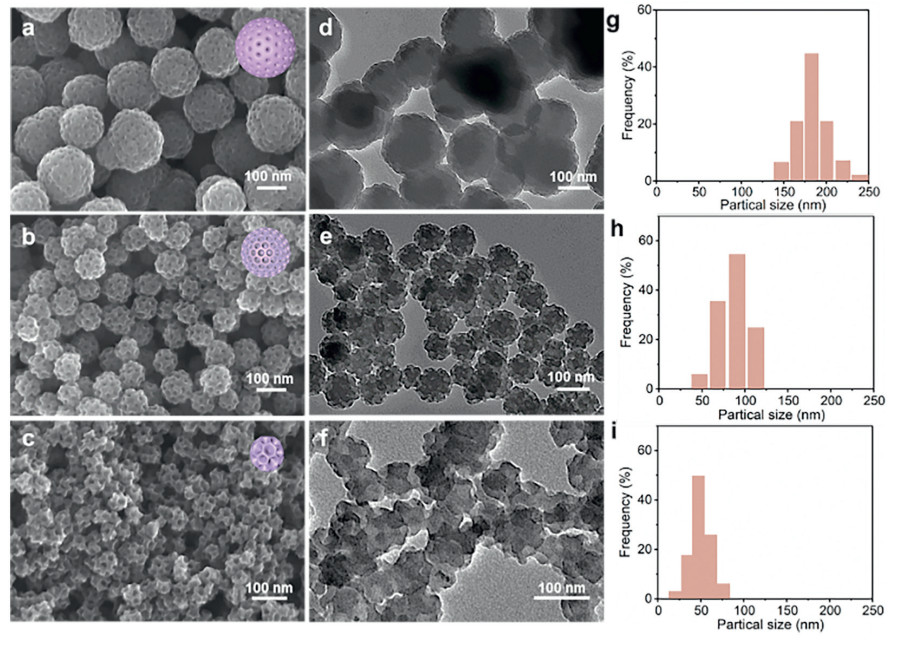
The significance of the block copolymers and water content in the formation of the mesoporous polypyrrole (mPPy) polymers with versatile architectures was further established (Fig. 2). Compared with manifold mPPy manufactured by different water contents (Fig. S3 in Supporting information), the research was concentrated on water contents from 40 wt% to 70 wt%. Three typical architectures of mPPy were acquired under the circumstance of 42 wt%, 50 wt% and 67 wt% which were labelled as mPPy-1, mPPy-2 and mPPy-3, respectively. On the basis of the scanning electron microscope (SEM) images (Figs. 2a-c) and the transmission electron microscopy (TEM) images (Figs. 2d-f), mesopores were observed clearly, especially with the increase of water content. As shown in Figs. 2g-i), the average sizes of mPPy-1, mPPy-2 and mPPy-3 are 189, 88 and 56 nm according to NANO measurement, which is in accord with the SEM images and TEM images. In addition, PPy nanospheres prepared in different solvent systems, including 1,2-dioxane (Dio)/ethanol/H2O and N,N-dimethylformamide (DMF)/ethanol/H2O for a sufficient comparison (Fig. S4 in Supporting information). On account of different solubility parameters, utilizing Dio (δ = 20.5) could achieve a similar effect, while disorder particles were obtained in DMF (δ = 24.8). Besides, the average of mesopores is about 15 nm through TEM images. What is noteworthy is that the construction of pores is isolated and evident with water content increasing. It is not difficult to come to the conclusion that the reduced number of micelles per unit volume can impair the crosslinking and aggregation effect and then influence the particle sizes and the distances of pore canals, which is in accord with the deduction mentioned before.
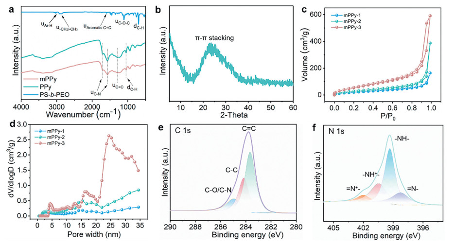
To make out the polymerization feature of obtained samples, different characterization tools were applied. The Fourier transform infrared (FT-IR) spectroscopy and X-ray diffraction (XRD) was examined first. Conjugated C-N stretching bands at 1310 cm−1, C-H bending bands at 1050 cm−1 and C = C stretching bands at 1570 cm−1 can be observed distinctly from the FT-IR profiles of mPPy, PPy and PS-b-PEO (Fig. 3a) [30]. The similar infrared absorption signals from 500 cm−1 to 4000 cm−1 between mPPy and PPy without characteristic peaks of PS-b-PEO demonstrate the success of polymerization. As shown in Fig. 3b, there is a wide strong diffraction peak around 25° derived from π-π stacking [31,32]. Besides, Fig. 3c displays N2 adsorption and desorption isotherms of obtained samples, which conform with the typical IV curves, particularly mPPy-3. The H3-type hysteresis loop verifies the existence of mesopores [28]. Surprisingly, there is an unprecedented result that the BET surface area of mPPy-3 is 192 m2/g (Table S1 in Supporting information), which surpasses existing reports on specific surface areas of conducting polymers [33-35]. Fig. 3d also exhibits that the sizes of mesopores are approximately 3 nm and 15 nm, consistent with SEM and TEM images. The pores at 15 nm are induced by the template, PS-b-PEO, while the emergence of smaller mesopores is due to the stacking of the polypyrrole chains and particles during the secondary assembly. X-ray photoelectron spectroscopy (XPS) was further used to investigate chemical compositions of mPPy. In the C 1s spectrum (Fig. 3e), three characteristic peaks centered at 286, 284.8 and 283.5 eV can be assigned to C-O/C-N, C-C and C = C, respectively. Another four peaks centered at 402.1 eV for = N+–, 400.5 eV for –NH+–, 399.3 eV for –NH–, and 398.2 eV for = NH– appeared in the N 1s spectrum (Fig. 3f). Based on the above analysis, it is verified that this synthesis of hierarchical N-rich mesoporous PPy nanospheres is feasible and tunable.
Inspired by the high theoretical specific capacity (2596 mAh/g) of red phosphorus, RP was employed into N-MCNs so that the composite can give play to their advantages. The fabrication process of the N-MCNs@RP composite is exhibited in Fig. 4a. The N-MCNs@RP composite is obtained by employing a vaporization-condensation method after carbonizing mPPy nanospheres. The high N/C ratio of PPy ensures that abundant N atoms can be incorporated into the carbon framework homogeneous during the carbonization process. On account of the high specific surface area of mPPy-3, it was chosen to investigate the characteristics after carbonization. N2 adsorption-desorption isotherms were examined first to analyze the porosities of the obtained N-MCNs. As shown in Fig. 4b, the specific surface area reaches up to 315 m2/g and the size of mesopores is around 20 nm. SEM characterization further revealed that the mesoporous structure could be stably maintained during the carbonization process (Fig. S5 in Supporting information). X-ray photoelectron spectroscopy (XPS) was measured to reveal the chemical interactions between RP and N-MCNs. In the P 2p spectrum (Fig. 4c), three characteristic peaks centered at 131.4, 133.6 and 134.2 eV can be assigned to P-C, P-N and P-O, respectively [36]. The XPS survey spectra established chemical interactions between RP and N-MCNs in light of the deviations of these P-P bond peaks. Compared with the Raman spectroscopy of N-MCNs and N-MCNs@RP (Fig. 4d), a remarkable peak at around 400 cm−1 appears on the curve of N-MCNs@RP, demonstrating that RP was imported into N-MCNs successfully. There are no other changes observable in the carbon Raman peak, indicating that the incorporation of RP does not result in structural damage to the N-MCNs.

The theoretical calculation was executed because it could provide more insights into the energy storage mechanism of N-MCNs@RP. As shown in Fig. 4e and Fig. S6 (Supporting information), RP would be absorbed into the carbon network through the electrostatic interaction with carbonyl groups and N heteroatoms after encapsulating RP into N-MCNs. All of them constructed the active region to coordinate with Na+. In order to deduce the mutual effect between RP and N-MCNs, the differential charge density was analyzed by VASP. The blue region and red region represent electron accumulation and electron depletion respectively. When RP is introduced, the carbon framework appears evident in charge transfer. The electrons on the carbon network are enriched around P, indicating the strong electron adsorption capacity and the ability of charge transfer. Besides, polarized pyridine N atoms can regulate the distribution of RP by chemical bond cooperation. The density of states (DOS) which is exhibited in Fig. 4f was calculated after absorbing RP on N-MCNs. DOS calculations show that N-MCNs@RP composite is still keep a good conductor property despite introducing RP, confirming that N-MCNs@RP have a very good perspective of energy storage application.
In order to examine the properties of the N-MCNs@RP composite electrode, the cyclic voltammetry (CV) was conducted at 0.1 mV/s in a voltage window of 0.01–2.0 V when it was applied to Na-ions batteries (Fig. 5a). Two reductive peaks can be observed visibly at 0.05 and 0.23 V during the second cathodic scan. In the second anodic scan, there are also two peaks at 0.55 V and 0.68 V. The excellent stability of the N-MCNs@RP composite is confirmed through the CV curves because of steady reductive/oxidation peaks appearing in each loop. Fig. 5b displays the charge/discharge profiles of the first three cycles of the N-MCNs@RP composite electrode at 0.4 A/g, which is in accord with the results of the CV curves. High discharge/charge capacities of 1817.6 and 915.8 mAh/g with an initial Coulombic efficiency (ICE) of 50.4% calculated through the mass of RP are obtained in the first cycle. The irreversible capacity fading is caused by the generation of an SEI film. Notably, the specific capacity of the N-MCNs is negligible (Fig. S7 in Supporting information). To further clarify the advantages of mesoporous structures, the electrochemical performance of PPy-derived N-doped carbon nanosphere (N-CNs) served RP host was performed. The electrochemical impedance spectroscopy (EIS) profile of the N-MCNs@RP composite electrode is shown in Fig. 5c. Compared with the N-CNs@RP, the arc radius of N-MCNs@RP composite electrode in the high-frequency region indicating a lower charge transfer impedance. The steeper slope of N-MCNs@RP composite electrode indicates a faster ion transport rate and higher electrochemical capacitance in the low-frequency region. These superiorities can be attributed to abundant mesopores and higher electronic conductivity promoted by N-MCNs. Porous structure facilitates the penetration of the electrolyte, shortening the ion diffusion distance, and a high specific surface area provides more active sites and contact interfaces between the electrolyte and the electrode. In addition, the higher conductivity of N-MCNs (0.9 S/cm) can compensate for the low conductivity of red phosphorus (10−14 S/cm). Fig. 5d and Fig. S8 (Supporting information) exhibit the rate performance of N-MCNs@RP and N-CNs@RP composite electrodes from 0.4 A/g to 6.0 A/g. The N-MCNs@RP composite shows stable reversible capacities of 1049.1, 808.7, 722.2, 630.0, 520.8, 458.0, and 381.9 mAh/g at 0.4, 1.0, 1.6, 2.0, 3.0, 4.0 and 6.0 A/g, respectively. For a sufficient comparison, the electrode of N-CNs@RP composite, a control sample, delivers inferior capacities and poor Coulombic efficiencies. When the current density returns to 0.4 A/g, a reversible capacity of 927.7 mAh/g is obtained, which proves that the nanostructure of the N-MCNs@RP composite is in good condition after high-rate discharge/charge. Compared with some previously reported RP-based anodes, the N-MCNs@RP composite electrode exhibits exceptional rate performance in sodium-ion batteries (Fig. S9 in Supporting information). It can be attributed to the hierarchical mesoporous nanostructure and abundant loading space, which improve the electrode-electrolyte contact and alleviate the volume expansion.
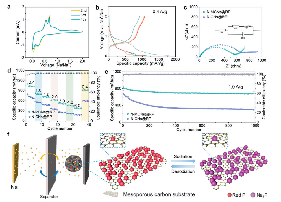
Besides, the N-MCNs@RP composite electrode was measured at 1.0 A/g for 1000 cycles to investigate its long cycling performance, exhibiting superior first charge capacities of 856 mAh/g and enhanced capacity of 679.6 mAh/g with a capacity fading rate of only 0.025% per cycle after 1000 cycles. (Fig. 5e). The extra-large pore volume accounts for the superb cycling performance because it can prevent the destruction of the nanostructure in the process of discharging and charging. Additionally, the Na-ion batteries based on the N-MCNs@RP composite electrode can power a timer displayer well, revealing its application potential in electronic devices (Fig. S10 in Supporting information). Accordingly, the charging and discharging processes of prepared Na ions half batteries are shown in Fig. 5f. Through vaporization and condensation, ultrasmall RP could be trapped in the pores of N-MCN evenly. During the discharge process, RP would be changed to Na3P, while the mesoporous imposes restrictions on the movement of Na3P and provides enough space for volume expansion.
In summary, mesoporous polypyrrole with tunable pore sizes and spherical nanoarchitectures has been obtained, which can be directly converted into N-doped carbon with regular mesoscopic pores and high surface area. Combined experimental and computational studies have shown that the unique structural design of N-MCNs can significantly accommodate mechanical stress and enhance the electronic conductivity of RP effectively, delivering exceptional electrochemical performance with high reversible capacity and reliable long-term cycling stability. The N-MCNs@RP composite electrode shows a high reversible capacity of 856 mAh/g, an enhanced capacity of 679.6 mAh/g with a capacity fading rate of only 0.025% per cycle after 1000 cycles at 1.0 A/g and a superior rate capability (384.7 mAh/g at 6.0 A/g). Our research provides fresh insight for synthesizing tunable N-doped mesoporous carbon nanospheres and paves a new way for the application of RP-based anodes in practice.
The authors declare no conflict of interest.
Hongyi Zhang: Data curation, Investigation, Methodology, Writing – original draft, Formal analysis. Wenda Li: Methodology, Writing – review & editing, Conceptualization. Hao Luo: Conceptualization, Methodology. Lingyan Huang: Writing – review & editing. Facai Wei: Writing – review & editing, Methodology. Shanzhe Ke: Writing – review & editing. Liguo Ma: Funding acquisition. Chengbin Jing: Funding acquisition, Resources. Jiangong Cheng: Funding acquisition. Shaohua Liu: Funding acquisition, Project administration, Supervision, Writing – review & editing, Conceptualization, Resources.
This work was financially supported by the National Natural Science Foundation of China (Nos. 52373208 and 61831021) and the Shanghai Undergraduate Training Program on Innovation and Entrepreneurship (No. 202310269131S).
Supplementary material associated with this article can be found, in the online version, at doi:
P.K. Nayak, L.T. Yang, W. Brehm, P. Adelhelm, Angew. Chem. Int. Ed. 57 (2018) 102–120. doi: 10.1002/anie.201703772
Y. Jin, P.M.L. Le, P. Gao, et al., Nat. Energy 7 (2022) 718–725. doi: 10.1038/s41560-022-01055-0
R. Shi, L. Liu, Y. Lu, et al., Nat. Commun. 11 (2020) 178. doi: 10.1038/s41467-019-13739-5
Z. Hao, X. Shi, Z. Yang, L. Li, S.L. Chou, Adv. Funct. Mater. 32 (2022) 2208093.
D. Luo, C. Ma, J. Hou, et al., Adv. Energy Mater. 12 (2022) 2106716.
Z. Cheng, B. Zhao, Y.J. Guo, et al., Adv. Energy Mater. 12 (2022) 2103461. doi: 10.1002/aenm.202103461
W. Zhang, Y. Wu, Z. Xu, et al., Adv. Energy Mater. 12 (2022) 2201065. doi: 10.1002/aenm.202201065
J. Song, Z. Yu, M.L. Gordin, et al., Nano Lett. 14 (2014) 6329–6335. doi: 10.1021/nl502759z
S. Qiao, Q. Zhou, M. Ma, et al., ACS Nano 17 (2023) 11220–11252. doi: 10.1021/acsnano.3c02892
J. Zhao, X.X. He, W.H. Lai, et al., Adv. Energy Mater. 13 (2023) 2300444. doi: 10.1002/aenm.202300444
Z. Li, M. Han, Y. Zhang, et al., Adv. Sci. 10 (2023) 2207234. doi: 10.1002/advs.202207234
Q. Jin, K. Wang, P. Feng, et al., Energy Stor. Mater. 27 (2020) 43–50.
X. Jiao, Y. Liu, B. Li, et al., Carbon 148 (2019) 518–524. doi: 10.1016/j.carbon.2019.03.053
W. Zhang, T. Liu, Y. Wang, et al., Nano Energy 90 (2021) 106475.
Y. Jiang, M. Xie, F. Wu, et al., Chem. Eng. J. 438 (2022) 134279. doi: 10.1016/j.cej.2021.134279
Y. Lu, P. Zhou, K. Lei, et al., Adv. Energy Mater. 7 (2017) 1601937.
Z. Yan, Y. Liang, W. Hua, et al., ACS Nano 14 (2020) 10284–10293. doi: 10.1021/acsnano.0c03737
B. Sun, S. Wang, S. Zhou, et al., Adv. Funct. Mater. 34 (2024) 2314058. doi: 10.1002/adfm.202314058
R. Mogensen, J. Maibach, A.J. Naylor, R. Younesi, Dalton Trans. 47 (2018) 10752–10758. doi: 10.1039/c8dt01068d
K. Fang, D. Liu, X. Xiang, et al., Nano Energy 69 (2020) 104451. doi: 10.1016/j.nanoen.2020.104451
H. Kaur, B. Konkena, C. Gabbett, et al., Adv. Energy Mater. 13 (2022) 2203013.
Y. Liu, Q. Liu, C. Jian, et al., Nat. Commun. 11 (2020) 2520. doi: 10.1038/s41467-020-16077-z
X. Liu, B. Xiao, A. Daali, et al., ACS Energy Lett. 6 (2021) 547–556. doi: 10.1021/acsenergylett.0c02650
W. Liu, L. Du, S. Ju, et al., ACS Nano 15 (2021) 5679–5688. doi: 10.1021/acsnano.1c00924
S. Zhang, C. Liu, H. Wang, et al., ACS Nano 15 (2021) 3365–3375. doi: 10.1021/acsnano.0c10370
S. Liu, P. Gordiichuk, Z.S. Wu, et al., Nat. Commun. 6 (2015) 8817. doi: 10.1038/ncomms9817
F. Wei, H. Xu, T. Zhang, et al., ACS Nano 17 (2023) 20643–20653. doi: 10.1021/acsnano.3c07868
L. Peng, C.T. Hung, S.W. Wang, et al., J. Am. Chem. Soc. 141 (2019) 7073–7080. doi: 10.1021/jacs.9b02091
F. Wei, T. Zhang, R. Dong, et al., Nat. Protoc. 18 (2023) 2459–2484. doi: 10.1038/s41596-023-00845-4
W. Li, L. Shi, Y. Wu, et al., Energy Stor. Mater. 53 (2022) 183–191. doi: 10.3390/antiox11020183
P. Huang, T. Xiong, S. Zhou, et al., ACS Appl. Mater. Interfaces 13 (2021) 16516–16527. doi: 10.1021/acsami.1c02645
U. Sreevidya, V. Shalini, S. Kavirajan, et al., J. Colloid Interface Sci. 630 (2023) 46–60. doi: 10.1016/j.jcis.2022.09.056
L. Xiang, S. Yuan, F. Wang, et al., J. Am. Chem. Soc. 144 (2022) 15497–15508. doi: 10.1021/jacs.2c02881
J. Liu, H. Li, J. Wang, et al., Adv. Energy Mater. 11 (2021) 2101926. doi: 10.1002/aenm.202101926
J. Xu, F. Yu, J. Hua, et al., Chem. Eng. J. 392 (2020) 123694. doi: 10.1016/j.cej.2019.123694
G.L. Chai, K. Qiu, M. Qiao, et al., Energy Environ. Sci. 10 (2017) 1186–1195. doi: 10.1039/C6EE03446B

Figure 2 Microstructure and morphology of prepared mPPy nanospheres. (a-c) SEM images, (d-f) TEM images and (g-i) particle size distribution of the synthesized samples.

Figure 3 (a) FTIR spectra of PS-b-PEO, PPy, mPPy. (b) XRD patterns of mPPy. (c) N2 adsorption-desorption isotherm and (d) pore size distribution of mPPy. XPS spectra of (e) C 1s and (f) N 1s of mPPy.

Figure 4 (a) Schematic illustration of the synthesis process for the N-MCNs@RP composite. (b) N2 sorption isotherms of N-MCNs. (c) XPS spectra of P 2p of N-MCNs@RP composites. (d) Raman spectra of N-MCNs and N-MCNs@RP composite. (e) Adsorption energy and corresponding charge density difference of N-MCNs@RP composite. (f) Density of states analysis for N-MCNs@RP composite.

Figure 5 (a) CV curves of the N-MCNs@RP composite half-call at a scan rate of 0.1 mV/s. (b) Discharge/charge profiles of the N-MCNs@RP composite electrode between 0.01 V and 2 V at a current density of 0.4 A/g. (c) EIS plots of the N-MCNs@RP composite electrode. (d) The rate performance of the N-MCNs@RP and N-CNs@RP composite electrodes at the current densities of 0.4–6.0 A/g. (e) The long cycling stability of the N-MCNs@RP and N-CNs@RP composite electrodes at 1.0 A/g. (f) Illustration of the discharge/charge processes of N-MCNs@RP in Na ions half batteries.

 扫一扫看文章

扫一扫关注我们
 DownLoad:

 下载:
下载: