Received Date:
10 September 2024 Accepted Date:
29 October 2024 Revised Date:
23 October 2024 Available Online:
15 February 2026
Abstract:
Commercial carbonate electrolytes suffer from ion transport difficulty in bulk electrolytes and interphase at low temperatures, bringing challenges to the application of lithium-ion batteries (LIBs) at low temperatures. Herein, the ester solvent of methyl propionate (MP) with low melting point and low viscosity was used to tackle ion transport difficulty in electrolytes. Fluorinated ester was further added to accelerate interfacial transport through intermolecular interactions. The influence of fluorinated esters with different fluorination degrees on the solvation structure of electrolytes and the performance of batteries was further studied. As a result, methyl pentafluoropropionate (M5F) with five fluorine atoms was selected for its optimal interactions with both Li+ and MP solvent in the primary solvation structure, contributing to desired solvation structure for fast interfacial transport. The LiFePO4 (LFP)||graphite cell with LiFSI-MP-M5F electrolyte exhibited a high cyclability of 85.8% after 120 cycles and retained 81.2% of room-temperature capacity when charged and discharged at −30 ℃. 1 Ah LFP||graphite pouch cell with high cathode loading (20 mg/cm2) in LiFSI-MP-M5F electrolyte exhibited 0.85 Ah capacity when charged and discharged at −20 ℃. This work provides a guidance for electrolyte design by synergistic fluorinated and non-fluorinated solvents for LIBs at low-temperature application.
Lithium-ion batteries (LIBs) as efficient energy storage devices, have the advantages of high energy density, low self-discharge, and long lifespan [1-5]. However, the performance of LIBs deteriorates significantly in low-temperature environment, exhibiting energy and power density loss, cycle life degradation and even safety issues [6-10]. The performance of LIBs at low temperatures is significantly hindered by the commercial carbonate electrolytes, which suffer from ion transport difficulty in bulk electrolytes and interphase at low temperatures [11-15]. Therefore, designing electrolyte with low melting point, low viscosity, and optimal solvation structure of fast interfacial transport is pivotal to improve the performance of LIBs at low temperatures [16-20].
Carboxylic esters, such as methyl propionate (MP) with low melting point and low viscosity, are widely used as the solvent to realize good ion transport in the electrolytes at low temperatures [21-25]. However, carbonates and carboxylic esters both have strong affinity with Li+, leading to sluggish interfacial transport. Fluorinated solvents have weak Li+ affinity and good electrochemical stability [26-28]. The application of fluorinated solvents is an effective approach to improve the interfacial transport and stability. Li+ affinity of fluorinated solvents is highly dependent on the fluorination degree, corresponding to the number of fluorine atoms. With the increase of fluorination degree, the electron-withdraw effect of fluorine atoms is enhanced, and the electronegativity of the oxygen atom is obviously weakened, resulting in the weakening of the interaction between oxygen atom and Li+ [29-32]. When the fluorinated solvent is used as single solvent in the electrolyte, it has been found that the solvent substituted with two fluorine atoms have lower Li+ binding energy than one fluorine atom and higher salt dissociation capacity than three or more fluorine atoms [33, 34]. When the fluorinated solvent is mixed with non-fluorinated solvents in the electrolyte, the fluorination degree can be higher due to the existence of the non-fluorinated solvent that can dissociate the lithium salt. For example, high fluorination degree of 1,1,2,2-tetrafluoroethyl-2,2,3,3-tetrafluoropropylether (TTE) and 1,1,2,2-tetrafluoroethyl-2′,2′,2′-trifluoroethyl ether (HFE) are applied as fluorinated solvents, which can effectively reduce the viscosity of electrolytes [35-39]. The fluorinated solvents also form atypical hydrogen bonds effect with non-fluorinated solvents by δO−-δH+ or δF−-δH+ interaction, leading to beneficial solvation structures [40, 41]. However, the fluorination degree of fluorinated solvents and their interaction with Li+ and non-fluorinated solvent has been rarely studied. Therefore, it is necessary to establish a universal relationship between the fluorination degree and interaction principle of fluorinated solvents.
Herein, MP with low melting point (−87.5 ℃), low viscosity (0.431 cP, 25 ℃) was used as the non-fluorinated solvent. The fluorinated solvents with different fluorination degrees were mixed with the MP solvent, and their synergistic effects on the solvation structure and electrochemical performance at low temperatures were explored. It was found that the fluorinated solvents with low fluorination degree, such as methyl trifluoroacetate (M3F) that has three fluorine atoms can largely participate in the primary solvation structure of Li+, which is not conducive to interfacial transport kinetics. Fluorinated solvents with high fluorination degree, such as methyl heptafluorobutyrate (M7F), which has atypical hydrogen bond with MP, is difficult to enter the primary solvation structure of Li+. Only fluorinated solvent with medium fluorination degree of methyl pentafluoropropionate (M5F) can enter the primary solvation structure of Li+ and simultaneously form atypical hydrogen bond with MP. It contributes to a desired solvation structure with weak Li+-solvent interactions and optimized interfacial transport kinetics. The LFP||graphite cell with LiFSI-MP-M5F electrolyte exhibited a high cyclability of 85.8% after 120 cycles and retained 81.2% of room-temperature capacity when charged and discharged at −30 ℃. 1 Ah LFP||graphite pouch cell with high cathode loading (20 mg/cm2) in LiFSI-MP-M5F electrolyte exhibited 0.85 Ah capacity when charged and discharged at −20 ℃.
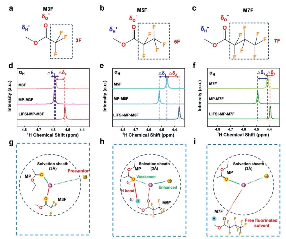
In this study, a class of fluorinated solvents for the MP-based electrolytes of LIBs have been systematically investigated. The interaction mechanism of fluorinated solvents substituted with different number of fluorine atoms, such as M3F and ethyl trifluoroacetate (E3F) with three fluorine atoms, M5F and ethyl pentafluoropropionate (E5F) with five fluorine atoms, as well as M7F and ethyl heptafluorobutyrate (E7F) with seven fluorine atoms have been studied (Figs. 1a-c and Fig. S1 in Supporting information). Fluorinated solvents with higher fluorination degree exert stronger electron-withdraw effect, thus enhancing the positive electrostatic potential of the hydrogen atoms in methyl or ethyl groups at the α position of carboxylic esters (αH), thereby promoting the atypical hydrogen bonds of δH+ in fluorinated solvents with δO− in MP solvent. From the 1H NMR spectra of solvents, it can be found that there is almost no chemical shift (Δδ1) of M3F or E3F before and after mixing MP (Fig. 1d and Fig. S2 in Supporting information), while the chemical shifts (Δδ1) of M5F, E5F, M7F and E7F after mixing MP are obvious shifted to the downfield (Figs. 1e and f, Figs. S3 and S4 in Supporting information). This demonstrated the existence of intermolecular hydrogen bonds between non-fluorinated solvents and fluorinated solvents with more than five fluorine atoms [42].
Figure 1
Figure 1.
The interaction mechanism of fluorinated solvents substituted with different number of fluorine atoms. (a) Fluorinated solvent substituted with three fluorine atoms of M3F. (b) Fluorinated solvent substituted with five fluorine atoms of M5F. (c) Fluorinated solvent substituted with seven fluorine atoms of M7F. (d) 1H NMR of M3F, MP-M3F and LiFSI-MP-M3F. (e) 1H NMR of M5F, MP-M5F and LiFSI-MP-M5F. (f) 1H NMR of M7F, MP-M7F and LiFSI-MP-M7F. The schematic illustrations of solvation structure and interaction mechanism in (g) LiFSI-MP-M3F, (h) LiFSI-MP-M5F and (i) LiFSI-MP-M7F electrolytes.
However, fluorinated solvents with as many as seven fluorine atoms, M7F or E7F, exist outside the primary solvation structure of Li+. The intermolecular hydrogen bond is difficult to affect the solvation structure. There is almost no chemical shift (Δδ2) in the 1H NMR spectra of M7F and LiFSI-MP-M7F (E7F and LiFSI-MP-E7F) in Fig. 1f and Fig. S4 (Supporting information). Therefore, only M5F and E5F simultaneously interact with MP to form intermolecular hydrogen bond and participate in the solvation structure. The hydrogen bond is further proved by the upfield shift of 17O NMR spectra for MP after mixing with M5F in Fig. S5 (Supporting information). Molecular dynamics (MD) simulation was performed to further investigate the solvation structure (Fig. S6 in Supporting information). According to the radial distribution function (RDF), the primary solvation structure is defined as the molecules within the 3 Å distance range of Li+ [43]. MP, M5F, and anion exist within the 3 Å of Li+, indicating their participation in the primary solvation structure. Besides, the coordination number of M5F is less than that of anion and MP solvents. Meanwhile, in LiFSI-MP-M3F electrolyte, M3F substantially attend the primary solvation structure, resulting in decreased anions inside the primary solvation structure compared to LiFSI-MP-M5F. In LiFSI-MP-M7F electrolyte, M7F molecules mainly exist outside the primary solvation structure in the form of free fluorinated solvent. Based on the solvation structure and interaction mechanism above, schematic illustrations of LiFSI-MP-M3F, LiFSI-MP-M5F and LiFSI-MP-M7F electrolytes are shown in Figs. 1g-i. M3F molecules have high binding energy with Li+, leading to sluggish de-solvation kinetics. M5F molecules that have moderate binding energy with Li+ can also attend the primary solvation structure. The hydrogen bonds of δO−-δH+ between MP and M5F can reduce the electronegativity of oxygen atom in MP, and significantly weaken the binding energy of MP with Li+, inducing accelerated de-solvation kinetics of MP. M7F molecules hardly participate the primary solvation structure to affect the de-solvation kinetics.
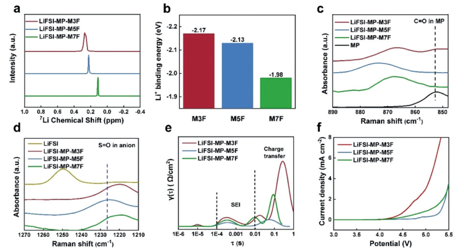
According to the 7Li NMR of LiFSI-MP-M3F, LiFSI-MP-E3F, LiFSI-MP-M5F, LiFSI-MP-E5F, LiFSI-MP-M7F and LiFSI-MP-E7F electrolytes (Fig. 2a and Fig. S7 in Supporting information), the peak of 7Li NMR shifts upfield with the increase of fluorine atoms. Meanwhile, for fluorinated solvents with the same fluorine atom number, fluorinated solvents with methyl group (M3F, M5F, M7F) are more favorable due to their relatively weaker Li+ affinity than those with ethyl group (E3F, E5F, E7F). The upfield shift of 7Li NMR is ascribed to gradually weakened interaction between Li+ and the fluorinated solvent with the increase of fluorine atoms. Decreased binding energies (from M3F, M5F to M7F) between fluorinated solvents and Li+ by density functional theory (DFT) further prove the weakened interaction with Li+ (Fig. 2b). For fluorinated solvents of E3F, E5F and E7F, their binding energies with Li+ are relatively higher and appear similar decrease tendency from E3F, E5F to E7F (Fig. S8 in Supporting information). The configuration of all molecules combining with Li+ were shown in Fig. S9 (Supporting information) and the binding energies were listed in Table S1 (Supporting information).
Figure 2
Figure 2.
Solvation structure of electrolytes with fluorinated and non-fluorinated solvents. (a) 7Li NMR spectra of electrolytes with M3F, M5F and M7F. (b) Binding energies between Li+ and different fluorinated solvents of M3F, M5F and M7F according to DFT simulations. (c) Raman spectra of MP solvent, LiFSI-MP-M3F, LiFSI-MP-M5F and LiFSI-MP-M7F electrolytes in the range of 890–845 cm−1, representing the stretching vibration of the C = O bond in MP solvent. (d) Raman spectra of LiFSI salt, LiFSI-MP-M3F, LiFSI-MP-M5F and LiFSI-MP-M7F electrolytes in the range of 1270–1210 cm−1, representing the stretching vibration of the S = O bond in FSI−. (e) Distribution of relaxation time (DRT) profiles of LFP||graphite cells with LiFSI-MP-M3F, LiFSI-MP-M5F and LiFSI-MP-M7F electrolytes at −30 ℃. (f) Oxidation stability of LiFSI-MP-M3F, LiFSI-MP-M5F and LiFSI-MP-M7F electrolytes according to linear sweep voltammetry (LSV) curves.
Raman spectra can further demonstrate the solvation structures (Fig. 2c). The vibration peak of C = O group near 853.5 cm−1 assigns free MP molecules, which has no interaction with Li+ or fluorinated solvents in the primary solvation structure [44]. In LiFSI-MP-M3F electrolyte, the peak of free MP still exists. In contrast, the peak of the free MP disappears in LiFSI-MP-M5F and LiFSI-MP-M7F. The coordinated MP peak in LiFSI-MP-M5F is located in 875.0 cm−1 and appears a more significant blue shift than LiFSI-MP-M7F electrolyte (868.0 cm−1). The disappearance of free MP peak and blue shift of coordinated MP peak indicate increased interaction on MP, which is ascribed to the hydrogen bond between the MP and M5F molecules. The hydrogen bond between MP and M5F anchors the free MP and affects the primary solvation structure of electrolytes. Besides, the peak of coordinated MP in LiFSI-MP-M5F electrolyte appears more obvious blue shift than that of LiFSI-MP-E5F electrolyte, indicating more significant interaction between MP and fluorinated solvent (Fig. S10 in Supporting information). The status of anion was further confirmed by the S = O stretching vibration peak of FSI− (Fig. 2d and Fig. S11 in Supporting information). The S = O peak in the LiFSI-MP-M5F electrolyte is located at 1226.2 cm−1, which is closer to crystalline LiFSI compared to other electrolytes, indicating stronger Li+-FSI− interaction, which contributes to the formation of anion-derived interface. According to the 1H NMR spectra and Raman spectra, fluorinated solvents with low fluorination degree, such as M3F can largely participate in the primary solvation structure, but merely interact with the MP solvent. Fluorinated solvents with high fluorination degree, such as M7F, have hydrogen bond with MP, but are difficult to enter the primary solvation structure of Li+. Only medium fluorination degree of M5F can enter the primary solvation structure and form hydrogen bond with MP.
The superiority of LiFSI-MP-M5F electrolyte in low-temperature applications was further proved by distribution of relaxation time (DRT) analysis in LFP||graphite cells at −30 ℃ (Fig. 2e). The peaks located at low frequency (0.01 s < τ < 1 s) and medium frequency (10−4 s < τ < 0.01 s) are assigned to charge transfer resistance (Rct) and resistance of interlayer (RSEI), respectively. Cells with LiFSI-MP-M5F electrolyte obtains lower Rct and RSEI, indicating rapid de-solvation kinetics as well as easier Li+ migration through solid electrolyte interface (SEI). Moreover, the peak positions of Rct indicate that cells with LiFSI-MP-M5F electrolyte also possess lower time constant, which further verifies the rapid de-solvation kinetics in such electrolyte [45]. Besides, the Li+-FSI− interaction as well as the anchoring effect of hydrogen bond [41] for free MP contribute to the highest oxidation stability of LiFSI-MP-M5F electrolyte according to the linear sweep voltammetry (LSV) curves (Fig. 2f). Considering the advantages of solvation structure, LiFSI-MP-M5F electrolyte was applied for further study.
The physicochemical properties such as the viscosity, ionic conductivity, liquid-phase window, Li+ transference number and the flammability of the LiFSI-MP-M5F electrolyte were compared with commercial carbonate electrolytes of 1 mol/L LiPF6/ethylene carbonate (EC)-diethyl carbonate (DEC) (1:1, v/v, abbreviated as LiPF6-EC-DEC) and 1 mol/L LiPF6/EC-ethyl methyl carbonate (EMC)-MP (1:3:1 by vol., abbreviated as LiPF6-EC-EMC-MP). Compared to LiPF6-EC-DEC with a sharp viscosity increase below −20 ℃ and solidifies at −30 ℃, both LiPF6-EC-EMC-MP and LiFSI-MP-M5F exhibit lower viscosity down to −30 ℃ and maintain a homogeneous liquid state at −80 ℃ (Figs. 3a and d, Fig. S12 in Supporting information). In addition, the ionic conductivity of LiFSI-MP-M5F is 3.1 mS/cm at room temperature and 1.5 mS/cm at −30 ℃, slightly lower than that of LiPF6-EC-EMC-MP (Fig. 3b). However, owning to the higher anion association with Li+ [46], Li+ transference number of the LiFSI-MP-M5F electrolyte reaches 0.81, which is higher than LiPF6-EC-EMC-MP (0.61) and LiPF6-EC-DEC (0.37), as shown in Fig. 3c and Fig. S13 (Supporting information). It indicates that the contribution ratio of Li+ transport to the total ions in the conductivity for the LiFSI-MP-M5F electrolyte is the highest among these three electrolytes. Due to the use of non-combustible fluorinated solvents, the flammability of LiFSI-MP-M5F is significantly reduced. Compared to the flammability of LiPF6-EC-EMC-MP and LiPF6-EC-DEC, the LiFSI-MP-M5F shows good flame retardancy and self-extinguishes within 5 s (Fig. 3e).
Figure 3
Figure 3.
Physicochemical properties of LiPF6-EC-DEC, LiPF6-EC-EMC-MP, and LiFSI-MP-M5F electrolytes. (a) Viscosity curves of different electrolytes when the temperature drops from room temperature to −30 ℃. (b) Ionic conductivity of different electrolytes when the temperature drops from room temperature to −80 ℃. (c) Li+ transference number of different electrolytes at room temperature. (d) Liquid-phase states of different electrolytes at −30 ℃ overnight. (e) Flammability of different electrolytes.
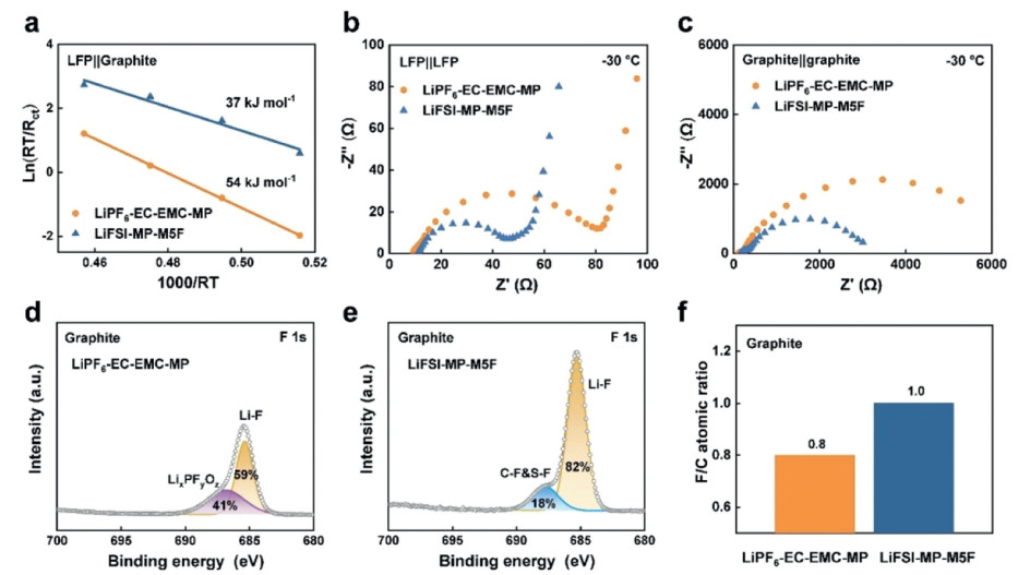
Interfacial transport of LFP||graphite cells with LiFSI-MP-M5F and LiPF6-EC-EMC-MP were further compared for low-temperature application. Temperature-dependent impedances were tested on LFP||graphite cells. The lower energy barrier of LiFSI-MP-M5F electrolyte verified its accelerated charge transfer kinetics. The activation energy of LFP||graphite cells with LiFSI-MP-M5F is only 2/3 that of LiPF6-EC-EMC-MP, indicating a faster interfacial transport of LiFSI-MP-M5F (Fig. 4a). To figure out the main influence factor of the interfacial transport, the resistance tests of LFP||LFP symmetrical cells and graphite||graphite symmetrical cells at 50% state of charge with different electrolytes were carried out at −30 ℃ (Figs. 4b and c). The interfacial transport impedance of graphite symmetrical cell is two orders of magnitude higher than that of LFP symmetrical cell at −30 ℃, indicating that the interfacial transport on graphite is a key factor for the battery performance at low temperatures. At low temperatures, interfacial transport on graphite interface is dominated by the de-solvation kinetics, which is determined by solvation structure of electrolytes [47]. The impedance of graphite||graphite symmetrical cells with LiFSI-MP-M5F is only half of that with LiPF6-EC-EMC-MP, which verifies that the LiFSI-MP-M5F electrolyte has better interfacial transport kinetics.
Figure 4
Figure 4.
Interfacial transport of cells with LiFSI-MP-M5F and LiPF6-EC-EMC-MP. (a) Activation energies corresponding to the interfacial transport for LFP||graphite cells with different electrolytes. (b) Nyquist plots of LFP||LFP symmetrical cells with different electrolytes at −30 ℃. (c) Nyquist plots of graphite||graphite symmetrical cells with different electrolytes at −30 ℃. The XPS spectra of F 1s for cycled graphite anodes with (d) LiPF6-EC-EMC-MP and (e) LiFSI-MP-M5F. (f) The F/C atomic ratio of interface components for cycled graphite anodes with different electrolytes.
X-ray photoelectron spectroscopy (XPS) for cycled graphite anodes was characterized to further analyze the interfacial composition on graphite surface in different electrolytes. According to the XPS spectra of F 1s (Figs. 4d and e) and C 1s (Fig. S14 in Supporting information), the SEI of graphite in LiFSI-MP-M5F electrolyte obtains more inorganic components, such as Li2CO3 (290 eV) and LiF (685 eV) (Fig. 4e and Fig. S14 in Supporting information) [48, 49]. Interfacial component formed with LiFSI-MP-M5F has a higher F/C atom ratio (1.0) compared to LiPF6-EC-EMC-MP (0.8), indicating a higher abundance of inorganic species (Fig. 4f). The inorganic compounds are associated with the decomposition of anions, which is attributed to the more FSI− participation in the primary solvation structure for LiFSI-MP-M5F. Compared with thick and porous interface in LiPF6-EC-EMC-MP, anion-derived interface in LiFSI-MP-M5F not only obtains lower interfacial impedance, but also helps to realize reversible Li+ intercalation for better cycling stability at low temperatures [50].
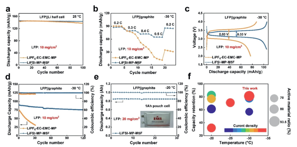
Battery performance was tested to verify the advantage of the proposed LiFSI-MP-M5F electrolyte. LFP||Li half cells (Fig. 5a) and graphite||Li half cells (Fig. S15 in Supporting information) were tested with 1 C at room temperature. The LFP||Li cell with LiPF6-EC-EMC-MP decayed by 5% after 100 cycles, while graphite||Li cell decayed by 70% after 100 cycles at 1 C. It proves the cycling performance of batteries with LiPF6-EC-EMC-MP is mainly limited by the graphite anode. Poor electrode compatibility of LiPF6-EC-EMC-MP electrolyte is attributed to the side reaction of active free MP and unstable interface. In contrast, LFP||Li cell and graphite||Li cell with LiFSI-MP-M5F decayed by only 1.6% and 7.8%, respectively. LFP||graphite cells with a cathode loading of 1.5 mAh/cm2 (10 mg/cm2) and N/P ratio of 1.1 were assembled. Cells with LiFSI-MP-M5F electrolyte show good cycle stability at room temperature, retaining 86.0% capacity after 100 cycles at 1 C (Fig. S16 in Supporting information). LFP||graphite cells with LiFSI-MP-M5F electrolyte also obtained good rate performance at room temperature, retaining a capacity of 95.0 mAh/g at 5 C (82.8% of the capacity at 1 C) (Fig. S17 in Supporting information). Battery performance at low temperature were further tested. Through the rate test from 0.2 C to 0.5 C at −30 ℃, it can be found that the advantage of LiFSI-MP-M5F electrolyte is more obvious with the increase of rate, which indicates its better interfacial transport kinetics (Fig. 5b). This is mainly due to the rapid ion transport ability at the graphite interface in the LiFSI-MP-M5F electrolyte. The overpotential of the cell using the LiFSI-MP-M5F electrolyte was only half that of the LiPF6-EC-EMC-MP electrolyte when charged and discharged at 0.1 C and −30 ℃. The cell with LiFSI-MP-M5F electrolyte obtained a discharge capacity of 105.5 mAh/g (81.2% of room-temperature capacity). In comparison, the cell with LiPF6-EC-EMC-MP only delivered 77.0 mAh/g (Fig. 5c). The LFP||graphite cell with LiFSI-MP-M5F electrolyte exhibited high capacity retention of 85.8% after 120 cycles at −30 ℃ and 0.2 C with an average Coulombic efficiency of 99.8%, while the capacity of the cell with LiPF6-EC-EMC-MP drop sharply in less than 50 cycles at −30 ℃ (Fig. 5d).
Figure 5
Figure 5.
Electrochemical performance of LFP||graphite cells with LiFSI-MP-M5F and LiPF6-EC-EMC-MP. (a) Cycling performance of LFP||Li half cells with different electrolytes at 25 ℃ and 1 C. (b) Rate performance, (c) voltage profiles at 0.1 C and (d) cycling performance at 0.2 C of LFP||graphite cells (1.5 mAh/cm2 cathode loading, N/P = 1.1) different electrolytes at −30 ℃. (e) Cycling performance 1 Ah LFP||graphite pouch cell (3.0 mAh/cm2 cathode loading, N/P = 1.1) with LiFSI-MP-M5F electrolyte at −20 ℃ and 0.1 C. (f) Electrochemical performance comparison with reported works for LFP||graphite cells operated at low temperatures.
To further confirm the application of LiFSI-MP-M5F electrolyte in practical conditions, 1 Ah LFP||graphite pouch cell with a high cathode loading of 3.0 mAh/cm2 (20 mg/cm2) and N/P ratio of 1.1 in LiFSI-MP-M5F electrolyte were assembled and stably cycled for over 50 times at 25 ℃ and 1 C (Fig. S18 in Supporting information). The pouch cell with LiFSI-MP-M5F electrolyte also maintained stable after 30 charge-discharge cycles and exhibited 0.85 Ah discharge capacity (85% of room-temperature capacity) at −20 ℃ and 0.1 C (Fig. 5e and Fig. S19 in Supporting information). At −30 ℃ and −40 ℃, LFP||graphite pouch cells with LiFSI-MP-M5F electrolyte still discharged 76.1% and 55.6% of room-temperature capacity, respectively (Fig. S20 in Supporting information). Compared with reported electrolytes for LFP||graphite cells (Fig. 5f and Table S2 in Supporting information), LiFSI-MP-M5F electrolyte shows superior battery performance at low temperatures with high cathode loading and high active material ratio.
Synergistic fluorinated and non-fluorinated solvents for LIBs at low-temperature application are investigated in this work. The solvation structure of the electrolyte can be optimized through the often overlooked but crucial interaction between fluorinated and non-fluorinated solvents. M5F substituted with five fluorine atoms was selected because it has hydrogen bond interaction with MP in the primary solvation structure, contributing to desired solvation structure for fast interfacial transport. The proposed LiFSI-MP-M5F electrolyte enabled the LFP||graphite cell with a high cyclability of 85.8% after 120 cycles and retained 81.2% of room-temperature capacity when charged and discharged at −30 ℃. 1 Ah LFP||graphite pouch cell with high cathode loading (20 mg/cm2) in LiFSI-MP-M5F electrolyte exhibited 0.85 Ah when charged and discharged at −20 ℃. The design criteria of fluorinated solvents optimal electrolytes in this work will provide reference for the electrolyte design of LIBs at low-temperature application.
Declaration of competing interest
The authors declare that they have no known competing financial interests or personal relationships that could have appeared to influence the work reported in this paper.
CRediT authorship contribution statement
Xuning Gao: Writing – original draft, Methodology, Investigation, Data curation, Conceptualization. Nan Piao: Writing – review & editing, Writing – original draft, Validation, Methodology, Investigation, Funding acquisition, Conceptualization. Yukun Yan: Methodology, Data curation. Jinghao Wang: Methodology, Investigation, Data curation. Haolun Zou: Methodology, Investigation, Data curation. Siqi Guan: Methodology, Investigation, Data curation. Leiying Zeng: Resources, Funding acquisition. Zhenhua Sun: Writing – review & editing, Supervision. Guangjian Hu: Writing – review & editing, Investigation, Data curation. Feng Li: Writing – review & editing, Visualization, Validation, Supervision, Project administration, Funding acquisition.
Acknowledgments
This work was supported by the National Key R & D Program of China (No. 2022YFB3803400), National Natural Science Foundation of China (Nos. 52102054, 52020105010, 51927803, 52188101 and 52072378), Liaoning Province Science and Technology Planning Project (No. 2022-BS-007), Fujian Science and Technology Program (No. 2023T3025).
Supplementary materials
Supplementary material associated with this article can be found, in the online version, at doi:10.1016/j.cclet.2024.110591.
[1]
J.M. Tarascon, M. Armand, Nature 414 (2001) 359–367. doi: 10.1038/35104644
Figure 1
The interaction mechanism of fluorinated solvents substituted with different number of fluorine atoms. (a) Fluorinated solvent substituted with three fluorine atoms of M3F. (b) Fluorinated solvent substituted with five fluorine atoms of M5F. (c) Fluorinated solvent substituted with seven fluorine atoms of M7F. (d) 1H NMR of M3F, MP-M3F and LiFSI-MP-M3F. (e) 1H NMR of M5F, MP-M5F and LiFSI-MP-M5F. (f) 1H NMR of M7F, MP-M7F and LiFSI-MP-M7F. The schematic illustrations of solvation structure and interaction mechanism in (g) LiFSI-MP-M3F, (h) LiFSI-MP-M5F and (i) LiFSI-MP-M7F electrolytes.
Figure 2
Solvation structure of electrolytes with fluorinated and non-fluorinated solvents. (a) 7Li NMR spectra of electrolytes with M3F, M5F and M7F. (b) Binding energies between Li+ and different fluorinated solvents of M3F, M5F and M7F according to DFT simulations. (c) Raman spectra of MP solvent, LiFSI-MP-M3F, LiFSI-MP-M5F and LiFSI-MP-M7F electrolytes in the range of 890–845 cm−1, representing the stretching vibration of the C = O bond in MP solvent. (d) Raman spectra of LiFSI salt, LiFSI-MP-M3F, LiFSI-MP-M5F and LiFSI-MP-M7F electrolytes in the range of 1270–1210 cm−1, representing the stretching vibration of the S = O bond in FSI−. (e) Distribution of relaxation time (DRT) profiles of LFP||graphite cells with LiFSI-MP-M3F, LiFSI-MP-M5F and LiFSI-MP-M7F electrolytes at −30 ℃. (f) Oxidation stability of LiFSI-MP-M3F, LiFSI-MP-M5F and LiFSI-MP-M7F electrolytes according to linear sweep voltammetry (LSV) curves.
Figure 3
Physicochemical properties of LiPF6-EC-DEC, LiPF6-EC-EMC-MP, and LiFSI-MP-M5F electrolytes. (a) Viscosity curves of different electrolytes when the temperature drops from room temperature to −30 ℃. (b) Ionic conductivity of different electrolytes when the temperature drops from room temperature to −80 ℃. (c) Li+ transference number of different electrolytes at room temperature. (d) Liquid-phase states of different electrolytes at −30 ℃ overnight. (e) Flammability of different electrolytes.
Figure 4
Interfacial transport of cells with LiFSI-MP-M5F and LiPF6-EC-EMC-MP. (a) Activation energies corresponding to the interfacial transport for LFP||graphite cells with different electrolytes. (b) Nyquist plots of LFP||LFP symmetrical cells with different electrolytes at −30 ℃. (c) Nyquist plots of graphite||graphite symmetrical cells with different electrolytes at −30 ℃. The XPS spectra of F 1s for cycled graphite anodes with (d) LiPF6-EC-EMC-MP and (e) LiFSI-MP-M5F. (f) The F/C atomic ratio of interface components for cycled graphite anodes with different electrolytes.
Figure 5
Electrochemical performance of LFP||graphite cells with LiFSI-MP-M5F and LiPF6-EC-EMC-MP. (a) Cycling performance of LFP||Li half cells with different electrolytes at 25 ℃ and 1 C. (b) Rate performance, (c) voltage profiles at 0.1 C and (d) cycling performance at 0.2 C of LFP||graphite cells (1.5 mAh/cm2 cathode loading, N/P = 1.1) different electrolytes at −30 ℃. (e) Cycling performance 1 Ah LFP||graphite pouch cell (3.0 mAh/cm2 cathode loading, N/P = 1.1) with LiFSI-MP-M5F electrolyte at −20 ℃ and 0.1 C. (f) Electrochemical performance comparison with reported works for LFP||graphite cells operated at low temperatures.

 DownLoad:


 下载:
下载:


