Figure 1.
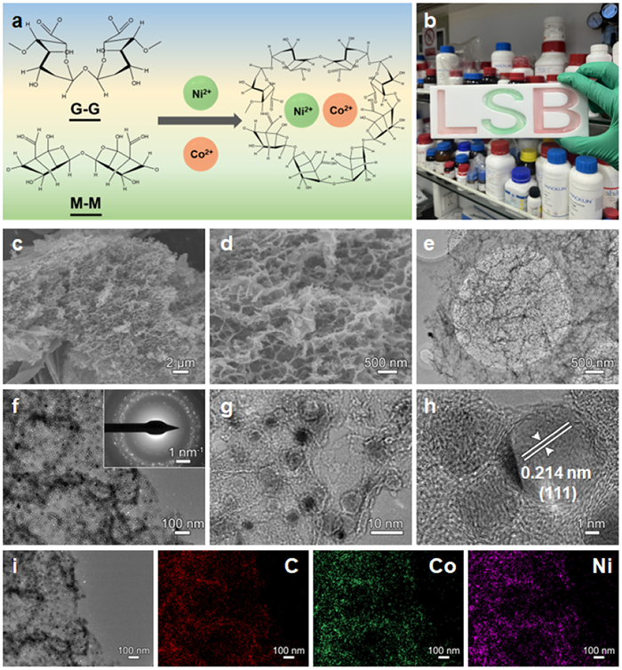
(a) Schematic diagram of the synthesis of SA/NiCo. (b) Hydrogels of different shapes. (c, d) SEM, (e-h) TEM and (i) EDS images of SAC/NiCo.
Gelation-pyrolysis strategy for fabrication of advanced carbon/sulfur cathodes for lithium-sulfur batteries
Feng Cao , Chunxiang Xian , Tianqi Yang , Yue Zhang , Haifeng Chen , Xinping He , Xukun Qian , Shenghui Shen , Yang Xia , Wenkui Zhang , Xinhui Xia

Lithium-sulfur batteries (LSBs) are the most promising next-generation battery system due to their high energy density (2600 Wh/kg), low gravimetric densities (Li: 0.534 g/cm3; S: 2.07 g/cm3), large theoretical capacities (Li: 3860 mAh/g; S: 1675 mAh/g) and abundant sources [1-4]. Despite of these impressive merits, the commercialization of LSBs is still impeded by several issues on sulfur cathodes, including: (1) Shuttling effect of soluble polysulfides results in irreversible loss of sulfur and side-reactions on anode, which causes unsatisfactory capacity decay and Coulombic efficiency (CE). (2) Sluggish reaction kinetics of insulating sulfur would lead to high polarization and low sulfur utilization. Thus, it is essential to develop multifunctional sulfur hosts with enhanced electronic conductivity, superior adsorption properties and excellent catalytic ability, thus simultaneously suppressing the shuttle of polysulfides and enhancing the electrochemical kinetics to realize high performance LSBs with long life [5-13].
To solve these problems, hierarchical composite hosts with high polarity, large specific surface area, unique porous structure and enhanced electronic conductivity have aroused tremendous attentions. Among these, carbonaceous carbon materials (e.g., carbon nanotubes, activated carbon, carbon fibers, graphene, and carbon quantum dots) are considered as the satisfactory skeleton due to its unique pore architecture, lightweight characteristic and high conductivity, which are synthesized via conventional hydrothermal, electrospinning, electrochemical exfoliation, and chemical vapor deposition technologies [8,14-17]. However, these synthesis processes typically involve multiple steps and hazard reactors/products, thus resulting in high product cost, low yield, and uncontrollability in morphology, dimensionality, and composition [18-31]. Up to now, scientists have developed several natural inspired technologies, including puffing carbonization technology, biological self-assembly technology, fermentation technology, etc. to realize the high compatibility and controllability of carbon-based composite materials [32-36]. For instance, our group developed multifunctional Rhizopus hyphae carbon fiber (RHCF) and its derivatives (e.g., CoO, NbO, Cr2O3) via the interactions of electronegative amino acids are and positive metal cations as the sulfur hosts in LSBs [37-43]. As results, the well-designed LSB full cell shows superior cycling performance and enhanced high-rate capacity (881.3 mAh/g at 1 C). Despite of the precise control of micro/macro-structures, the reported hierarchical carbon materials derived from natural inspired technologies are mainly limited in micron scale due to the intrinsic size of nature precursors. To further improve the accommodation space and physical confinement of sulfur, it is urgent to develop network precursors in nanoscale. Sodium alginate (SA), sourced from natural brown marine algae, has been widely concerned due to their supramolecular architecture composed of β-d-mannuronate (M-unit) and α-l-guluronate (G-unit) monomers, which are arranged as the interspersed blocks of MM, GG and GM. Based on the chelation ability to various metal ions, such as Ca2+, Cu2+, Zn2+, Fe2+, Co2+, Ni2+ and V3+, the combination of metal ions and alginate can in-situ induce the nanoscale network of hydrogel matrix [40,44,45]. After carbonization, the metal ions are converted to metal-based nanoparticles with enhanced specific surface area. To date, there is no work on construction of nanoscale hierarchical carbon composites via the metal ion induced chelation process, let alone their applications as lithium sulfur batteries.
Herein, for the first time, we synthesize the SAC-based composites via metal ion induced chelation process to construct hierarchical carbon composites with tunable compositions and controllable morphologies in nanoscale. The well-designed architecture shows unique nanoscale networks, excellent mechanical stability and high electronic conductivity. Interestingly, the crosslinking ability of the bimetallic ions system to SA is significantly higher than that of monometallic. With the introduction of Ni2+ and Co2+, the binding energy of the Ni2+Co2+-G unit reactions is −15.28 eV, much higher than that of Ni2+-G unit reactions (−7.76 eV). After the pyrolysis process, the SAC/NiCo composite exhibits enhanced porosity and specific surface area, which can effectively confine polysulfides via the physical/chemical adsorptions. Meanwhile, the NiCo alloy nanoparticles display improved catalytic stability to accelerate the conversion kinetics of polysulfides. When applied as cathodes for LSBs, the SAC/NiCo-S electrode shows superior electrochemical performances with higher rate capacity (2 C: 693.5 mAh/g) and enhanced cycling stability (764.3 mAh/g at 0.1 C after 240 cycles) to other counterparts.
The fabrication schematic of SA-based composites via metal ion induced chelation process is shown in Fig. 1a. Firstly, 2% w/v SA solution was dispensed and ejected into the collection bath consisted of the 1% NiSO4 and 1% CoSO4 complex solution at a steady flow rate of 0.5 mL/min. After injection, the uniform SA/NiCo hydrogel beads were formed in the bath solution due to the substitution of Na+ by Ni2+ and Co2+, which induced cross-linking between the polymer chains, thereby constructing a network structure within the hydrogel [44,45]. As shown in Fig. 1b, hydrogels of different shapes were synthesized such as a “LSB”-like hydrogel. This process can be represented by the following equation:
|
|
(1) |
As confirmed in previous reports, the metal ions tend to affiliate with carboxyl and hydroxyl moieties on G units, thereby constructing a distinctive “egg-box” architecture. Moreover, due to the stereochemical hindrance and the diverse electronegativities of various ions, the bonding efficacies between various polyvalent ions and alginate polymer chains are different. And higher binding energy between metal ions and the SA molecules would result in enhanced compaction of SA crosslinking structure and larger specific surface area. Density functional theory (DFT) calculations were conducted to analysis the binding energies between metal ion-G unit reactions. As shown in Fig. S1 (Supporting information), the binding energy of the Ni2+Co2+-G unit reactions is −15.28 eV, much higher than that of Ni2+-G unit reactions (−7.76 eV), indicating that the enhancement of crosslinking ability of the bimetallic ion system of Ni2+ and Co2+ to SA compared to monometallic Ni2+. After that, the as-synthesized hydrogel beads were then freeze-dried to keep their microstructures from stacking. After the high-temperature pyrolysis process in Ar atmosphere, the SA with Ni and Co precursors would be transformed into macroscopic SAC/NiCo beads, which are composed of interconnected hierarchical carbon frameworks with numerous ultrasmall nanoparticles. As observed in scanning electron microscopy (SEM) (Figs. 1c and d) and high-resolution transmission electron microscopy (HRTEM) (Figs. 1e-h) images of the SAC/NiCo sample, the NiCo nanoparticles with diameters of 3–6 nm are uniformly dispersed in the carbon matrix without aggregation. Additionally, the interplanar spacing of NiCo alloy in Fig. 1g is 0.214 nm, much higher than (111) crystal plane of Ni phase (JCPDS No. 04–0850) due to the larger Co atomic radius.
As convinced in the energy dispersive spectrometer (EDS) and mapping images (Fig. 1i), the Ni and Co elements are homogeneously distributed in the SAC/NiCo composites. As supported by SEM images of SAC (Fig. S2 in Supporting information) and SAC/Ni (Fig. S3 in Supporting information), the bimetallic induced chelation-crosslinking process can produce much smaller nanoparticles and enhanced specific surface area than the monometallic counterpart, while SAC material is massive and shows few pores structure. During the freeze-drying and carbonization processes, the metal ions fuse and melt into the nanoparticle morphology while the polymer chains in micro-crystallined domains would convert into carbon chains. Subsequently, these carbon chains undergo a reconfiguration process to form graphitic layers. The in-situ formed carbon layers effectively induce the uniform dispersion of metal ions and impede aggregation and growth of metal nanoparticles. As demonstrated, the combination of carbon layers and Ni/NiCo nanoparticles endow the composite host with superior ion/electron conductivities and enhanced specific surface areas.
X-ray diffraction (XRD), Raman and X-ray photoelectron spectroscopy (XPS) were characterized to investigate the chemical compositions and phase information of the SAC, SAC/Ni and SAC/NiCo samples. As shown in Fig. 2a, as for SAC/Ni sample, in addition to the wide peak at 26.5° of SAC, another three diffraction peaks at 44.5°, 51.8° and 76.4° are observed, corresponding to the crystal planes of (111), (200), and (220) of Ni phase (JCPDS No. 04–0850). This result verifies the successful incorporation of Ni nanoparticles within the SAC matrix. In the case of SAC/NiCo composites, similar diffraction peaks are observed with a slightly downshift, attributing to the larger atomic radius of Co atoms.

Then, Raman spectra were further conducted to evaluate the graphitization degree of three samples. As displayed in Fig. 2b, two typical D and G bands are located at around 1338 and 1582 cm-1, which correspond to the disordered carbon and ordered graphitic carbon of SAC matrix, respectively. In comparison to SAC (ID/IG = 0.97), the SAC/Ni and SAC/NiCo show the higher graphitization degrees of 0.98 due to the catalytic action of metal ions. Furthermore, the detailed compositions of SAC/NiCo were detected by XPS. The wide-scan XPS spectrum of SAC/NiCo (Fig. S4 in Supporting information) demonstrates the existences of Ni, Co, C, O elements in SAC/NiCo sample. In the O 1 s spectrum (Fig. 2c), there exists Ni/Co-O bonding (529.8 eV) due to the interaction of metal ions and hydrophilic groups. As for the Ni 2p spectrum (Fig. 2d), there exist several characteristic peaks, including Ni2+ (Ni 2p3/2: 855.9 eV and Ni 2p1/2: 875.18 eV) and their planetary peaks (860.2 and 880.4 eV) as well as metallic Ni (853.8 and 870.8 eV). Compared to the Ni 2p spectrum of SAC/Ni (Fig. S5 in Supporting information), these peaks exhibit an upshift after alloying with Co atoms, due to the charge transfer occurring from Co to Ni. The Co 2p spectrum (Fig. 2e) in SAC/NiCo can be divided into three groups of characteristic peaks of Co2+ (Co 2p3/2: 779.0 eV and Co 2p1/2: 794.1 eV) and their planetary peaks (785.9 and 797.3 eV) as well as metallic Co (794.1 eV and 779.0 eV) [36,46,47]. Based on the XRD and XPS results, it can be observed that the SAC/Ni and SAC/NiCo are successfully synthesized. According to the Brunauer-Emmett-Teller (BET) analysis (Fig. 2f), the SAC/NiCo host exhibits a higher specific surface area (≈380.5 m2/g) than SAC/Ni (≈315.7 m2/g) and SAC (≈209.8 m2/g), which can be attributed to the NiCo bimetallic crosslinking. In virtue of the implanted highly graphitic carbon and a super hierarchical porous framework, SAC/NiCo can not only enhance the sulfur accommodation space and physical confinement, but also accelerate the sulfur redox reactions.
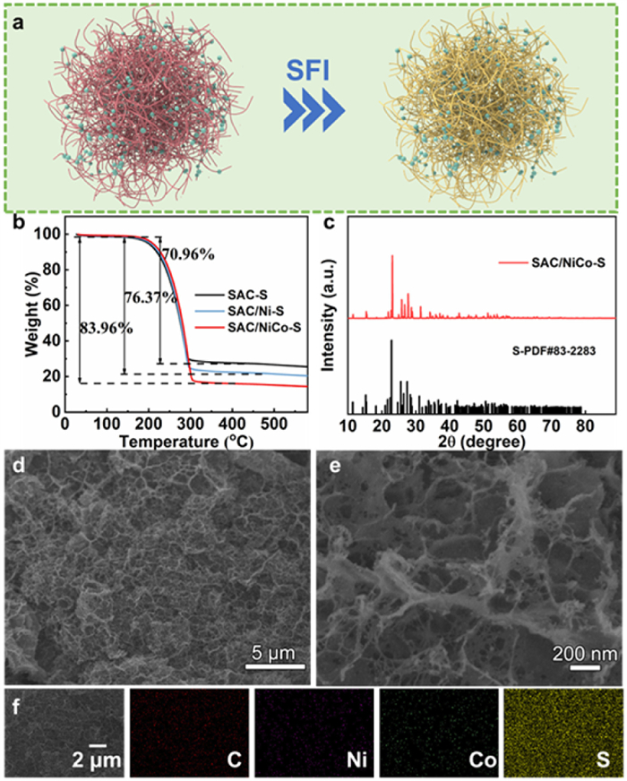
To explore the electrochemical application of different samples, SAC-S, SAC/Ni-S and SAC/NiCo-S cathodes were prepared through the steam sulfurizing process (Fig. 3a). Thermogravimetric (TG) analysis (Fig. 3b) reveals that the S loading of SAC/NiCo-S cathode is 83.96 wt%, much higher than SAC/Ni-S (76.37 wt%) and SAC-S (70.96 wt%) counterparts, which can be attributed to the in-situ implantation of NiCo nanoparticles and created pore architecture. XRD patterns (Fig. 3c) show characteristic peaks of sulfur (JCPDS No 83–2583), indicating the successful encapsulation of sulfur. The corresponding SEM (Figs. 3d and e) images indicate the pores on the surfaces of SAC/NiCo-S become smoother, indicating that sulfur is successfully and homogeneously infiltrated into the pores of SAC/NiCo-S skeletons after the steam sulfurizing in the whole architecture. Moreover, EDS (Fig. 3f) images of SAC/NiCo-S further confirm the uniformity of sulfur in the whole architecture.
To illustrate the superior electrochemical performance of SAC/NiCo-S cathode, cyclic voltammetry (CV) curves at 0.1 mV/s of SAC-S, SAC/Ni-S and SAC/NiCo-S cathodes were tested in LSBs. As shown in Fig. 4a, there are two pairs of redox peaks, which are indicative of the reversible reduction and oxidation processes involving the transformation of sulfur to long-chain soluble lithium polysulfides (Li2Sx, 4 ≤ x ≤ 8, R1/O1) and the conversion of short-chain solid lithium sulfides (Li2S2/Li2S, R2/O2). SAC/NiCo-S cathode shows the sharpest redox peaks and the lowest voltage polarization, indicating the excellent electrochemical redox reactivity. Furthermore, the accelerated electrochemical kinetic of SAC/NiCo-S cathode was convinced by the earliest onset potential of oxidation peak and the latest onset potential of reduction peak (Figs. 4b and c).
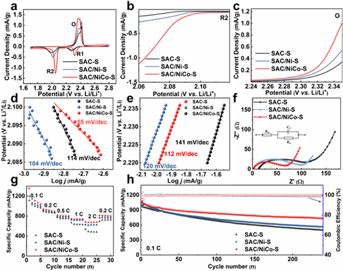
Then, Tafel slopes derived from CV curves were simulated to investigate the synthetic effect of SAC and NiCo nanoparticles on the electrochemical redox kinetics (Figs. 4d and e). The SAC/NiCo-S cathode possesses Tafel slopes of 55 (R2)/112 (O) mV/dec in reduction and oxidation processes, respectively, much smaller than SAC/Ni-S (104 (R2)/120 (O) mV/dec) and SAC-S (114 (R2)/141 (O) mV/dec) counterparts, manifesting that the well-designed architecture can synthetically accelerate both the reduction and oxidation processes. The electrochemical impedance spectroscopy (EIS) was conducted to analyze the charge transfer ability of the electrodes (Fig. 4f). The Rct of SAC/NiCo-S cathode is ≈65.2 Ω, significantly lower than that of SAC-S (≈105.1 Ω) and SAC/Ni-S (≈96.1 Ω) counterparts, further proving the fastest electrochemical reaction kinetics of SAC/NiCo-S cathode.
As expected, the enhanced electrochemical reaction kinetics significantly improved the rate capability (Fig. 4g) and cycling stability (Fig. 4h) of the SAC/NiCo-S cathode. As measured, the SAC/NiCo-S cathode exhibits a notable discharge capacity of 1070.6 mAh/g at 0.1 C after three cycles of activation, superior to the counterparts of SAC/Ni-S (1019.9 mAh/g) and SAC-S (983.0 mAh/g) electrodes. When the rate increases to 2 C, a capacity of 681.9 mAh/g is obtained for the SAC/NiCo-S cathode, much higher than SAC/Ni-S (625.6 mAh/g) and SAC-S (535.5 mAh/g) cathodes. Additionally, the capacity of SAC/NiCo-S cell recovers quickly to 92.1% of the initial capacity when the current density turns back to lower rate of 0.2 C, indicating its enhanced stability due to the combination of SAC and NiCo. To prove the superiority of SAC, the electrochemical property of conventional super P (SP) was detected. The discharge capacities of SP-S are 473.1, 410.2, 355.8, 326.5 and 291.9 mAh/g at the current densities of 0.1, 0.2, 0.5, 1, 2 C, respectively (Fig. S6a in Supporting information). When the discharge rate is back to 0.2 C, SP-S only reveals a capacity of 333.5 mAh/g. It can be observed that the SAC-S possess higher electrochemical properties at all of the current densities compared to the SP-S counterparts due to the enhanced specific surface area of 209.8 m2/g compared to SP counterpart 55.1 m2/g, revealing conducive effect of SAC for sulfur conversion process (Fig. S6b in Supporting information). Impressively, the SAC/NiCo-S cathode also displays prominent long-term cycling performance with a high discharge capacity of 1067.9 mAh/g at 0.1 C, higher than those of SAC/Ni-S (1042.7 mAh/g), and SAC-S (997.6 mAh/g) counterparts. After 240 cycles, the SAC/NiCo-S cathode remains a capacity of 764.3 mAh/g with a capacity retention of 71.5% (high coulombic efficiency of over 99.0%), much superior to SAC/Ni-S (562.2 mAh/g, 53.9%), and SAC-S (498.9 mAh/g, 50.0%). The improved performance of the SAC/NiCo-S composites can be primarily attributed to the combination of 3D hierarchical carbon network with unique pore architecture and uniformly dispersed NiCo nanoparticles, which effectively increases the accommodation space of sulfur loading, enhances physical/chemical adsorption and superior catalytic abilities to polysulfides, thus significantly suppressing the shuttling effect and enhancing the kinetic conversion of polysulfides.
Density functional theory (DFT) calculations were conducted to investigate the chemical interactions between polysulfides with the graphene and NiCo. The configurations of S8, L2S8, Li2S6, Li2S4, Li2S2, and Li2S on the surface of graphene, NiCo and Ni were established respectively as shown in Figs. 5a and b and Fig. S7 (Supporting information). As calculated (Fig. 5c), the adsorption energy of S8, L2S8, Li2S6, Li2S4, Li2S2, and Li2S with NiCo is −0.73, −1.11, −0.97, −0.87, −1.46, and −1.68 eV, respectively, much higher than that on the graphene (−0.69, −0.64, −0.73, −0.55, −0.67 and −0.59 eV) and Ni (−0.73, −0.84, −0.78, −0.62, −0.90, and −0.74 eV). Consequently, the incorporation of NiCo nanoparticles results in a significantly enhanced affinity toward polysulfides, thereby enhancing the chemical interaction to soluble polysulfides and enhanced electrochemical performance. Additionally, to further confirm the superior catalytic ability of NiCo, the simulations of catalytic conversion process on carbon, Ni and NiCo were investigated depicted in Fig. 5d.
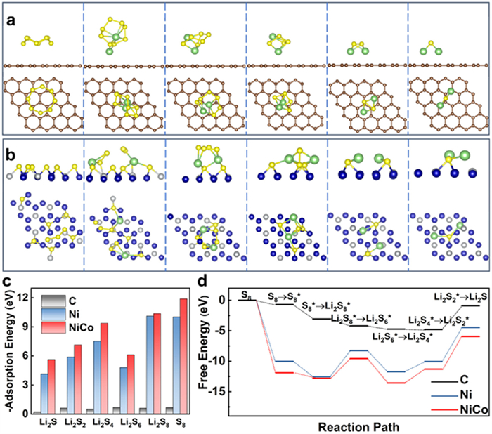
On pure carbon surface, the overall free energy of the reaction pathway is −0.92 eV, which is significantly higher than that on Ni (−1.1 eV) and NiCo (−2.0 eV). Remarkably, all reaction processes are exothermic and thermodynamically spontaneous state, and the combination of NiCo nanoparticles transforms the entire reaction process towards easiest and fastest condition. Based on the computations of free energies, it is manifest that the Li2S2 → Li2S conversion reaction with a positive free energy in LSBs is governed by the rate-determining step. The reduced overall positive energy from 3.92 eV (on pure carbon surface) to 3.60 eV due to NiCo nanoparticles in LSBs demonstrated a significant acceleration of reaction kinetics. As stated above, SAC/NiCo possesses optimal adsorption ability to polysulfides and reduced free energy of polysulfides conversion process, which can protect polysulfide molecules from partial surface vulcanization, improve the utilization rate of active substances, accelerate the catalytic conversion process and improve the reversibility of the electrochemical reaction.
In summary, we first propose a metal-ion induced in situ gelation-pyrolysis self-assembly strategy technology to construct sodium alginate carbon-based 3D polar porous hierarchical carbon composites with cross-linked network architecture and in-situ co-grown cross-linked polar nanoparticles. Interestingly, bimetallic cross-linked ions Ni2+ and Co2+ can effectively enhance the porosity of the SAC, thus providing more accommodation space for sulfur. The as-synthesized SAC/NiCo composite can serve as the sulfur hosts and displays improved electrochemical performances, attributing to the 3D hierarchical carbon matrix and in-situ implanted NiCo alloy nanoparticles. The architecture provides an adsorption-catalysis-conduction combined effect in cathodes, thus inhibiting the shuttle effect and improving the catalytic conversion kinetics of polysulfides. Accordingly, the designed SAC/NiCo cathode exbibits superior rate performance (2 C: 693.5 mAh/g) and cycling stability at 0.1 C (764.3 mAh/g after 240 cycles) owing to the synergistic enhancement arising from the metal alloy and carbon architecture. This work proposes a promising approach for developing advanced 3D porous carbonaceous composites for applications in advanced energy storage system.
The authors declare that they have no known competing financial interests or personal relationships that could have appeared to influence the work reported in this paper.
Feng Cao: Writing – review & editing, Project administration, Data curation. Chunxiang Xian: Writing – original draft, Data curation. Tianqi Yang: Software, Data curation. Yue Zhang: Project administration, Formal analysis. Haifeng Chen: Data curation, Conceptualization. Xinping He: Resources, Funding acquisition, Formal analysis. Xukun Qian: Funding acquisition, Formal analysis. Shenghui Shen: Writing – review & editing, Resources, Data curation. Yang Xia: Resources, Funding acquisition. Wenkui Zhang: Resources, Funding acquisition. Xinhui Xia: Writing – review & editing, Supervision, Resources, Project administration, Data curation.
This work is supported by National Natural Science Foundation of China (Nos. 52372235, 52073252, 22379020, 52002052, 52302316), Science and Technology Department of Zhejiang Province (Nos. 2023C01231, Q23E020046, LD22E020006, and LY21E020005), Zhejiang Provincial Postdoctoral Research Project (No. ZJ2023080), Key Research and Development Project of Science and Technology Department of Sichuan Province (No. 2022YFSY0004).
Supplementary material associated with this article can be found, in the online version, at doi:
J.B. Goodenough, K.S. Park, J. Am. Chem. Soc. 135 (2013) 1167–1176. doi: 10.1021/ja3091438
X. Shan, Y. Zhong, L. Zhang, et al., J. Phys. Chem. C 125 (2021) 19060–19080. doi: 10.1021/acs.jpcc.1c06277
C. Xian, Q. Wang, Y. Xia, et al., Small 19 (2023) 2208164. doi: 10.1002/smll.202208164
W. Lei, H. Li, Y. Tang, et al., Carbon Energy 4 (2022) 539–575. doi: 10.1002/cey2.180
C. Xian, P. Jing, X. Pu, et al., ACS Appl. Mater. Interfaces 12 (2020) 47599–47611. doi: 10.1021/acsami.0c14645
H. Li, H. Chen, Y. Xue, et al., Adv. Energy Mater. 10 (2020) 2001683. doi: 10.1002/aenm.202001683
Y. Li, J. Wu, B. Zhang, et al., Energy Storage Mater. 30 (2020) 250–259. doi: 10.1016/j.ensm.2020.05.022
D. Qiu, K. Zheng, T. Guan, et al., J. Alloys Compd. 991 (2024) 174230. doi: 10.1016/j.jallcom.2024.174230
M. Xiang, H. Wu, H. Liu, et al., Adv. Funct. Mater. 27 (2017) 1702573. doi: 10.1002/adfm.201702573
H. Chen, M. Zheng, S. Qian, et al., Carbon Energy 3 (2021) 929–956. doi: 10.1002/cey2.146
D. Yang, J. Wang, C. Lou, et al., ACS Energy Lett. 9 (2024) 2083–2091. doi: 10.1021/acsenergylett.4c00771
C. Li, D. Yang, J. Yu, et al., Adv. Energy Mater. 14 (2024) 2303551. doi: 10.1002/aenm.202303551
C. Wang, C. Yang, Y. Du, et al., Adv. Funct. Mater. 33 (2023) 2303427. doi: 10.1002/adfm.202303427
Q. Xiao, J. Yang, X. Wang, et al., Carbon Energy 3 (2021) 271–302. doi: 10.1002/cey2.96
L. Chen, Y. Yuan, R. Orenstein, et al., Energy Storage Mater. 60 (2023) 102817. doi: 10.1016/j.ensm.2023.102817
C. Li, C. Zheng, F. Cao, et al., J. Electron. Mater. 51 (2022) 4107–4114. doi: 10.1007/s11664-022-09687-4
Y. Li, Z. Qiu, L. Huang, et al., Chin. Chem. Lett. 35 (2024) 109510. doi: 10.1016/j.cclet.2024.109510
H. Shi, X. Zhao, Z.S. Wu, et al., Nano Energy 60 (2019) 743–751. doi: 10.1016/j.nanoen.2019.04.006
L. Hu, T. Yang, X. Yan, et al., ACS Nano 18 (2024) 8463–8474. doi: 10.1021/acsnano.4c00267
X. Xu, Y. Xu, J. Zhang, et al., Nano-micro Lett. 15 (2023) 56. doi: 10.1007/s40820-023-01031-7
T. Yang, W. Zhang, J. Lou, et al., Small 19 (2023) 2300494. doi: 10.1002/smll.202300494
J. Zhu, H. Su, X. Han, et al., Adv. Funct. Mater. 33 (2023) 2302229. doi: 10.1002/adfm.202302229
R. Wang, J. Qin, F. Pei, et al., Adv. Funct. Mater. 33 (2023) 2305991. doi: 10.1002/adfm.202305991
C. Xian, S. Zhang, P. Liu, et al., Small 20 (2024) e2306381. doi: 10.1002/smll.202306381
B. Liu, Y. Zhang, Z. Wang, et al., Adv. Mater. 32 (2020) e2003657. doi: 10.1002/adma.202003657
H. Zhang, L. Zhou, X. Du, et al., Carbon Energy 4 (2022) 1093–1106. doi: 10.1002/cey2.227
T. Yang, W. Zhang, Y. Liu, et al., Small 19 (2023) 2303210. doi: 10.1002/smll.202303210
D. Yang, Y. Han, M. Li, et al., Adv. Funct. Mater. 34 (2024) 2401577.
Y.X. Li, Y.S. Feng, L.X. Li, et al., Energy Storage Mater. 67 (2024) 103257. doi: 10.1016/j.ensm.2024.103257
Y.H. Liu, L.X. Li, A.Y. Wen, et al., Energy Storage Mater. 55 (2023) 652–659. doi: 10.1016/j.ensm.2022.12.028
D. Yang, C. Li, M. Sharma, et al., Energy Storage Mater. 66 (2024) 103240. doi: 10.1016/j.ensm.2024.103240
Z. Qiu, S. Shen, P. Liu, et al., Adv. Funct. Mater. 33 (2023) 2214987. doi: 10.1002/adfm.202214987
Y. Song, X. Li, C. He, Chin. Chem. Lett. 32 (2021) 1106–1110. doi: 10.1016/j.cclet.2020.08.024
W. Hua, H. Li, C. Pei, et al., Adv. Mater. 33 (2021) e2101006. doi: 10.1002/adma.202101006
G. Liu, W. Wang, P. Zeng, et al., Nano Lett. 22 (2022) 6366–6374. doi: 10.1021/acs.nanolett.2c02183
R. Wang, Z. Chen, Y. Sun, et al., Chem. Eng. J. 399 (2020) 125686. doi: 10.1016/j.cej.2020.125686
S. Shen, X. Xia, Y. Zhong, et al., Adv. Mater. 31 (2019) e1900009. doi: 10.1002/adma.201900009
L. Huang, S. Shen, Y. Zhong, et al., Adv. Mater. 34 (2022) e2107415. doi: 10.1002/adma.202107415
L. Huang, T. Guan, H. Su, et al., Angew. Chem. Int. Ed. 61 (2022) e202212151. doi: 10.1002/anie.202212151
B.L. Huang, H. Zhang, Z. Qiu, et al., Small 20 (2024) e2307579. doi: 10.1002/smll.202307579
Y. Zhong, X. Xia, S. Deng, et al., Adv. Mater. 30 (2018) e1805165. doi: 10.1002/adma.201805165
R. Zhou, S. Shen, Y. Zhong, et al., Chin. Chem. Lett. 33 (2022) 3981–3986. doi: 10.1016/j.cclet.2021.11.032
S. Shen, L. Huang, X. Tong, et al., Adv. Mater. 33 (2021) 2102796. doi: 10.1002/adma.202102796
D. Kang, Q. Liu, M. Chen, et al., ACS Nano 10 (2016) 889–898. doi: 10.1021/acsnano.5b06022
H. Zhang, Y. Lu, L. Huang, et al., Adv. Health. Mater. 13 (2024) e2303688. doi: 10.1002/adhm.202303688
S. Shen, Y. Chen, X. Gu, et al., Adv. Mater. 36 (2024) e2400245. doi: 10.1002/adma.202400245
C. Zhao, F. Huo, Y. Yang, et al., Adv. Funct. Mater. (2024) 2402175.

Figure 1 (a) Schematic diagram of the synthesis of SA/NiCo. (b) Hydrogels of different shapes. (c, d) SEM, (e-h) TEM and (i) EDS images of SAC/NiCo.

Figure 2 (a) XRD and (b) Raman of SAC, SAC/Ni and SAC/NiCo. XPS spectrum of (c) O 1s, (d) Ni 2p and (e) Co 2p signals for SAC/NiCo. (f) BET results of SAC, SAC/Ni and SAC/NiCo.

Figure 3 (a) Schematic fabrication process of SAC/NiCo-S. (b) TG results. (c) XRD, (d, e) SEM and (f) EDS results of SAC/NiCo-S.

Figure 4 (a) CV curves of SAC-S, SAC/Ni-S and SAC/NiCo-S. LSV curves from the (b) R2 reduction peak and (c) oxidation peak in CV curves. The derived Tafel plots from (d) R2 reduction peak and (e) O oxidation peak in CV curves. (f) Nyquist plots (and equivalent circuit diagram in inset). (g) Rate performance and (h) cycling performance of SAC-S, SAC/Ni-S and SAC/NiCo-S.

 扫一扫看文章

扫一扫关注我们
 DownLoad:
 下载:
下载:
