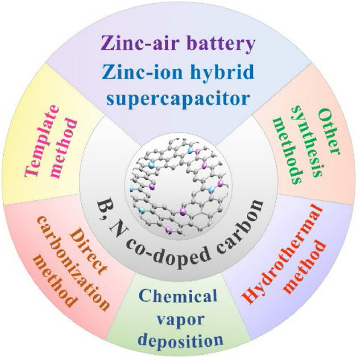
Figure 1.
Synthetic methods and applications of the BNC materials in ZESDs.
Synthesis and applications of B, N co-doped carbons for zinc-based energy storage devices
Hangwen Zheng , Ziqian Wang , HuiJie Zhang , Jing Lei , Rihui Li , Jian Yang , Haiyan Wang

The escalating energy and environmental challenges have underscored the urgent need for a transition to a greener and more sustainable energy landscape. To facilitate this conversion, it is imperative to explore environmentally friendly and cost-effective energy storage and conversion systems [1-3]. So far, lithium-ion batteries have emerged as the dominant players in the market thanks to their large specific capacity and high operating voltage; nevertheless, their widespread adoption is hindered by constraints such as limited lithium reserves and high cost [4-6]. Furthermore, the flammable organic electrolytes in lithium-ion batteries often raise significant safety concerns, necessitating the quest for safer alternatives [7]. Therefore, there is a critical and immediate demand for the development of greener, safer, and more efficient alternatives to propel the advancement of new energy industries.
As early as 1800, an innovative voltaic reactor using zinc as the negative electrode, was invented [8]. The success of the voltaic reactor has expedited the rapid development of the ZESDs [9-11]. Recently, various ZESDs such as zinc-air batteries (ZABs) [12,13], zinc-ion hybrid supercapacitors (ZHSCs) [14,15], and zinc-ion batteries [16-22], have been emerged as promising alternatives to lithium-ion batteries due to the high theoretical specific density, abundant reserves, outstanding safety, and environmental friendliness [23,24]. The blossoming of zinc-based energy storage technology has spurred research on various types of cathode materials, including carbon materials [25-28], manganese oxides [29-31], Prussian blue analogues [32-34], vanadium-based oxides [35-37]. Among the above, carbon materials featuring high conductivity, large specific surface area (SSA), tunable porous structure, and adjusted electronic structure have garnered significant interest, particularly in ZABs and ZHSCs [38,39]. However, the performance of pure carbon materials is still far from satisfactory owing to the lack of abundant adsorption sites and high intrinsic activity.
Heteroatom doping has been considered a general and promising strategy to improve the electrochemical properties of carbon materials [40,41]. Compared with the single-atom doping, the incorporation of multiple atoms with different properties into carbon materials is more fascinating [42,43]. Recently, boron (B), nitrogen (N) co-doped carbon (BNC) materials have attracted particular interest in ZESDs. It should be noted that when carbon atoms are replaced by B and N atoms, the electron donor properties and the Fermi level are changed, which are conducive to chemical adsorption and generate additional charge storage [44,45]. At the same time, the covalent bond formed by B and N is strong, which is beneficial for fixing N dopants, increasing the N content and significantly adjusting the chemical properties [46]. In addition, it has been demonstrated that B and N can collaboratively promote the formation of carbon defects and regulate the charge density [47]. Recently, using experiments and theoretical calculations, our group has proved that the B−N bonds can promote Zn ion adsorption and improve the electronic conductivity compared to other dual doped B and N sites, thus boosting the zinc-ion storage behavior [48]. In summary, the doping sites and the electronic structure of BNC have a profound impact on the electrochemical performance of ZESDs. However, to date, there are few reviews on BNC materials for ZESDs. Therefore, it is urgent to review it, which is conducive to further development and optimization.
Herein, we provide a comprehensive overview of the recent advances in BNC materials, focusing on their synthesis and applications in ZESDs (Fig. 1). Firstly, various synthetic techniques for BNC materials, including direct carbonization, template method, chemical vapor deposition (CVD), hydrothermal method, are summarized. Secondly, the key achievements on BNC materials in ZABs and ZHSCs in recent years are reviewed, providing insights into the potential benefits and limitations of BNC materials in zinc-based systems. Finally, the challenges and future development of BNC materials in ZESDs are prospected, hoping to promote the development and pave new ways for the practical application of BNC materials in this field in the future.
The direct carbonization is a widely used strategy for fabricating porous carbon materials [49-52]. As the temperature rises during the carbonization process, a series of chemical transformations take place and volatile components evaporate and escape, thus forming a porous structure. The resulting porous structure can provide a high SSA, which promotes mass transfer and electrochemical performance (Table S1 in Supporting information).
Recently, activated carbon fiber (ACC) was immersed in a mixture of urea, polyethylene oxide, propylene oxide, and boric acid, followed by a pyrolysis process at 900 ℃ to prepare a three-dimensional (3D) cross-linked BCN network on ACC (ACC@BCN) (Fig. 2a) [53]. As shown in Figs. 2b–e, each fiber of ACC@BCN is wrapped by porous BCN network. Benefiting from the interconnected network and high porosity, the ACC@BCN electrode delivers a high areal capacitance of 1018 mF/cm2 and a specific capacitance of 535.8 g/F at 1 mA/cm2 (Fig. 2f). Wang et al. employed glucose as the carbon source, ammonium chloride as the nitrogen source, and boron oxide as the boron source to prepare carbon spheres doped with B and N (B/N-CNS) [54]. During the pyrolysis process, CO, CO2, NH3, and other gases are formed, leading to abundant pores and large SSA. Thereby, the as-obtained B/N-CNS exhibit an interconnected porous structure with a large SSA of 504 m2/g (Figs. 2g–i), which favors charge storage and ion diffusion. Thus, a high capacitance and impressive rate capability are achieved with the B/N-CNS electrode (Fig. 2j).

In summary, the direct carbonization method is a simple and energy-consuming process, which is suitable for the large-scale preparation of the BCN materials. The high-temperature annealing favors the formation of porous architecture, large SSA and enhanced electric conductivity, thus boosting the energy storage or electrocatalytic performances. By controlling the direct carbonization process, the pore structure and doping amount of the BCN materials can be optimized to satisfy specific requirements for different applications. However, it is still a huge challenge to precisely control the doping sites of B and N. Therefore, more efforts should be made to regulate the pore structure and dopant sites to achieve the optimal electrochemical properties.
The template method offers a versatile approach for the synthesis of ordered porous carbon materials by replicating the texture or structure of template materials [55-59]. The template method can be categorized into hard template, soft template, and self-template methods [60,61]. Each of these templating methods has unique advantages and can be customized to precisely control the morphology and pore structure of the carbons.
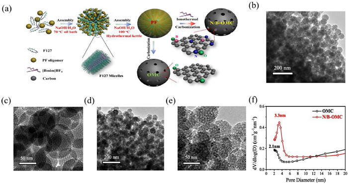
Recently, different templates have been adopted to prepare the BNC materials with different morphologies in order to achieve breakthroughs in performance [62]. For example, Qu et al. used melamine foam as a template, and polyethylene glycol, urea, and boric acid as auxiliary synthesis agents to synthesize the BCN nanotubes on a 3D carbon matrix [63]. By combining the template method and ion-thermal strategy, Chen’s group synthesized the N/B co-doped ordered mesoporous carbon spheres (N/B-OMC) [64]. In this process, F127 was served as a soft template, which was then assembled with the phenolic resin derived from the polymerization of phenol and formaldehyde. Meanwhile, 1-butyl-3-methylimidazole tetrafluoroborate ([Bmim]BF4) was taken as a medium for the ion-thermal process. Due to the presence of imidazole groups and BF4 ions, N/B co-doping can be realized after the insertion of the [Bmim]BF4 into the phenolic resin spheres (Fig. 3a). In contrast, ordered mesoporous carbon (OMC) was obtained by annealing phenol/formaldehyde resin directly. TEM images reveal that the obtained N/B-OMC material manifests a uniform spherical morphology, similar to that of OMC, suggesting that the B and N dual doping has little influence on the morphology (Figs. 3b–e). Furthermore, the N/B-OMC possesses a larger pore size and SSA compared to the OMC (Fig. 3f). The N/B-OMC thus achieves superior electrochemical performances. The invention of combining template method and ion-thermal strategy paves a new way for developing high-performance heteroatom-doped carbon materials.
Recently, ethyl cellulose and 4-(1-naphthyl)-phenylboric acid were introduced on the ZnO template to construct porous B,N-carbon nanomaterials (Fig. 4a) [65]. After annealing in NH3 atmosphere at 800 ℃, abundant micropores and carbon defects are formed in the carbon materials. SEM images show that the material retains the interconnected nanosheet structure of the ZnO template (Figs. 4b and c). Thanks to the hierarchical porous structure and the large SSA, the diffusion of reactants and the exposure of active sites can be enhanced, leading to excellent oxygen reduction reaction (ORR) activity with the initial potential reaching 0.98 V vs. the reversible hydrogen electrode (RHE) (Fig. 4d). Recently, by employing amino-functionalized graphene oxide (AGO) as the template, aniline, 3-aminophenylboric acid and m-phenylenediamine as the raw materials, the porous carbon nanomaterial (G-CBP-a) was obtained after two-step carbonization treatment, which exhibits a unique two-dimensional (2D) sheet architecture and high contents of heteroatoms (5.4% B and 5.3% N) (Fig. 4e) [66]. Combining the double-solvent impregnation with the nanoconfined-etching method, Wang et al. reported the preparation of B, N co-doped carbon (B,N@C) nanocages by using ZIF-8 template (Fig. 4f) [67]. Ammonia borane (AB) and boric acid (BA) were employed as B sources and etching agents. After pyrolysis, multimodal pores were generated in the B, N@C nanocages, contributing to superior ORR performance with an ultrahigh half-wave potential (E1/2) of 895 mV.

These findings demonstrate the feasibility of the template method in preparing BNC materials with unique morphology and pore structure. By selecting the appropriate template method and developing new templates, the electrochemical behavior of BNC materials can be enhanced. Moreover, a deeper understanding of the impacts of template on the structure, doping, and performance of BNC materials is crucial to further guide the optimization of BNC materials for energy storage and conversion applications.
CVD method shows outstanding advantages in the large-scale production of high-quality graphene [68-70]. By controlling the elementary steps of CVD, the number of layers and the structure of graphene can be adjusted precisely. Recently, CVD method was employed to fabricate BNC materials [71]. For example, to resolve the conflict between nitrogen content and electrical conductivity of N-doped carbon, Huang et al. introduced B and N dopants into carbon materials via a simple CVD method [72]. The as-prepared B-doped 3D carbon (TDC-B) maintains plentiful disordered mesopores, as observed from SEM and high-angle annular dark-field TEM (HAADF-TEM) images (Fig. 5a). Furthermore, X-ray photoelectron spectroscopy (XPS) was conducted to investigate how the B-dopant regulates the N-species (Figs. 5b and c). As shown in the N 1s XPS spectra, pyridinic N, pyrrolic N, graphitic N, and oxidic N can be found. In addition, the content of active N species increases with B dopant in TDC-B, laying the foundation for excellent electrochemical performances. Thanks to the regulation of B and N dual doping, TDC-B-0.50 exhibits an outstanding capacitive performance of 412 F/g (Fig. 5d). After 10,000 cycles in 1 mol/L H2SO4, the TDC-B-0.50 maintains a high capacitance retention of 97%, superior to most catalysts reported (Fig. 5e). This work provides an efficient way to tailor and stabilize N species in carbon materials for enhanced electrochemical performance.

In addition, the combination of CVD with other synthetic strategies is more attractive for the design of high-performance electrocatalysts [73]. In a recent work, 3D N, B co-doped carbon foam (NBC) was developed through the self-gelation of agar followed by the CVD process [74]. The obtained NBC shows a 3D carbon worm-like morphology and rich B and N heteroatoms, which favor the rapid charge and ion transportation. This work paves avenues to developing new BNC materials for energy storage devices.
Despite the numerous advantages in the CVD method, it is rarely used for the preparation of BNC materials. This limitation may be attributed to several factors, including the stringent preparation conditions, complex processes, and high costs [75]. As a result, there is a need to explore alternative strategies that are more energy-efficient and cost-effective for synthesizing BNC materials. Furthermore, a comprehensive understanding of the thermodynamics and formation mechanisms involved in the synthesis of BNC materials is essential for tuning the synthesis process and achieving desired properties.
Hydrothermal method has been demonstrated efficient for preparing BNC materials [76-78]. The properties of BNC materials can be tailored by adjusting reaction temperature, reaction time, pH, and other synthetic conditions [79-82]. Typically, the prepared product has the characteristics of high purity, good dispersion, and stable crystal structure, showing excellent performance.
A recent work describes the synthesis of B, N co-doped graphene oxide (GNB) using the hydrothermal method [80]. Specifically, the graphene oxide (GO) was added into a solution with a pH of 10 modulated by NH4OH and then transferred to a polytetrafluoroethylene reactor after mixing with N2H2. The hydrothermal reaction was conducted out at 120 ℃ for 2 h to prepare uniformly dispersed N-doped graphene (NG). Finally, the GNB was obtained through reacting with NaBH4. The as-prepared GNB maintains high-proportioned pyrrolic N, which is conductive for healing the defect planes in the graphene lattices, and thus contributes to the regulation of electronic characteristics of materials and prospects in long-term measurements (Figs. 6a and b).
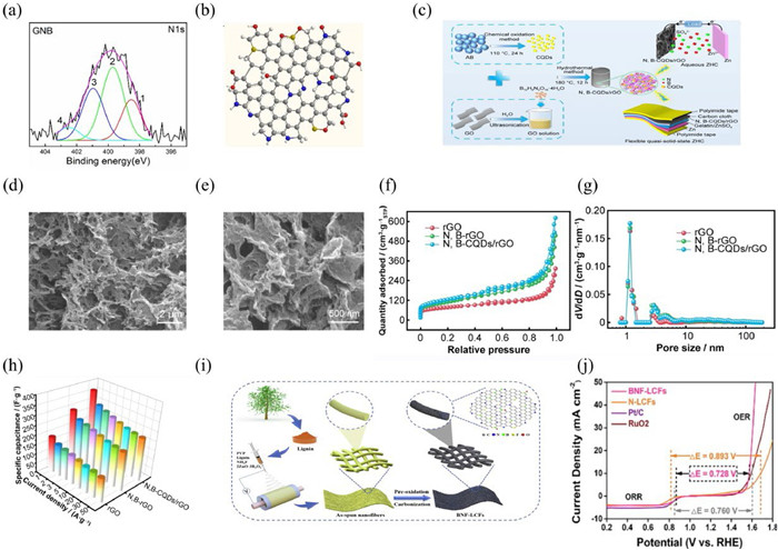
A simple one-step hydrothermal method was used to synthesize 3D N, B co-doped carbon quantum dots/reduced graphene oxide (N, B-CQDS /rGO), in which NH4B5O8 4H2O was employed as the N and B sources (Fig. 6c) [81]. The FESEM images show rich folds and porosity in the N,B-CQDs/rGO (Figs. 6d and e). The incorporation of carbon quantum dots not only effectually restrains the aggregation of rGO sheets, but also enlarges the interlayer distances, so as to improve the actual SSA of the composite aerogel to 447.9 m2/g (Fig. 6f). Moreover, the total porous volume of the N,B-CQDs/rGO (0.90 m3/g) surpasses those of the rGO and N, B-rGO (Fig. 6g). As displayed in Fig. 6h, the specific capacitances of the N,B-CQDs/rGO are much higher than that of the rGO and N,B-rGO. Therefore, N,B co-doping contributes to exposing more active sites and thereby improves the electrochemical performances in ZHSCs.
By combining microwave heating with hydrothermal techniques, Microwave hydrothermal technology has been widely applied in synthesizing nanomaterials due to the key advantages, such as rapid heating, enhanced mass transfer, and improved efficiency [36,83,84]. Importantly, microwave hydrothermal treatment can realize a homogeneous incorporation of heteroatoms due to the removal of thermal gradients in the reactors. Through microwave-assisted hydrothermal and pyrolysis processes, the synthesis of porous BNC composites was successfully realized [85]. The doping of B and N has a synergistic effect on the surface properties and electrochemical performance. According to previous reports, the increase in surface area generally enhances the charge storage capability of carbon-based materials. A maximum Brunner-Emmet-Teller (BET) surface area of 955 m2/g is achieved in BNC-10. When assembled into supercapacitors, a high energy density and a good capacitance retention rate can be obtained. This work provides an efficient and environmentally friendly way to prepare electrochemical materials.
Hydrothermal synthesis of the BNC has attracted growing interest due to its simple operation, cheap fabrication, and high yield. At present, coupling other force fields with hydrothermal systems is more intriguing and has a bright future for nanomaterial synthesis [86]. In addition, combining the hydrothermal method with other strategies such as the template method may be more appealing to achieve high-performance BNC materials. Therefore, it is hoped that hydrothermal preparation of BNC can make breakthroughs in the near future.
The electrospinning method can be used to prepare uniform fibers, which are conducive to electron transport and thus improve the electrochemical properties [82,87,88]. Recently, B, N, and F triple-doped lignin-based porous carbon nanofibers (BNF-LCFs) were prepared with biomass lignin, PCPC, zinc borate, and ammonium chloride by electrospinning and direct carbonization (Fig. 6i) [82]. The prepared BNF-LCFs catalyst exhibits a narrower energy gap (∆E) of 0.728 V compared to commercial Pt/C+RuO2, indicating its superior ORR and OER activity (Fig. 6j). The enhanced performance can be mainly attributed to the optimized electronic structures of the adjacent carbon atoms with B, N, F doping, the enhanced electron transmission and improves the stability aroused from interconnected carbon nanofibers. Sun et al. artificially prepared uniformly distributed B-O-C structure to improve surface wettability and electrolyte durability by using a spraying method [89]. For the synthesis, the aqueous solution containing boric acid, glucose, tetraethylorthosilicate, ethanol, hydrochloric acid, and deionized water is mixed and stirred. The solution is then atomized uniformly in the nitrogen division to form aerosol droplets, which are further transformed to nano-composites in a furnace at 450 ℃. The mixture was further carbonized at 900 ℃ to prepare the boron-doped nanoporous carbon (BDC). The method is suitable for preparing BNC materials on a large scale.
Compared to the previous synthetic strategies, the laser ablation method has been proved to be easier and cheaper to realize co-doping [90]. Adopting CO2 laser ablation, Manako et al. introduced B and N atoms into single-walled carbon nanohorns (BN-SWCNHs) under the N2 atmosphere [91]. The as-prepared BN-SWCNHs exhibit a flower-like architecture composed of thin graphite-like sheets (Figs. 7a and b). Raman spectra were further employed to investigate the degree of graphitization. Compared to the mono- or non-doped SWCNHs, the G’ peak around 2660.1 cm−1 for the BN-SWCNHs appears broader, which can be attributed to the coexistence of graphene sheets and tubular structures (Fig. 7c). To gain insight into the formation mechanism of BN-SWCNHs, N 1s and B 1s XPS spectra were analyzed (Figs. 7d and e). Because of the strong binding between B and N atoms, B−N bonds were found in BN-SWCNHs. The preferential formation of B−N bonds in BN-SWCNHs thus inhibits the graphitization, resulting in a mixture of CNHs and graphite-like sheets. The method paves a new way for the simple, rapid and efficient manufacture of functional carbon-based materials for energy storage and conversion.
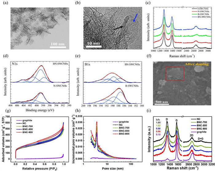
Instead of introducing nitrogen sources from other N-containing chemicals, the ball milling method demonstrates the potential of using air as the nitrogen source. Li and co-researchers synthesized the BNC materials by ball milling followed by annealing process [92]. Many smaller grains are formed in graphite after ball milling, indicating more edge defects (Fig. 7f). Thanks to the ball milling, the SSA of the BNC materials is greatly enhanced, which promotes the exposure of more active sites (Fig. 7g). Moreover, the BNC samples exhibit a mesoporous structure, which contributes to electrolyte penetration and ion diffusion (Fig. 7h). Compared to the primary graphite, the as-prepared BNC maintains stronger D bands, indicating the presence of plentiful defects (Fig. 7i). Besides, the intensity ratio between D band and G band (ID/IG) decreased with the increase of annealing temperature, manifesting a high graphitic degree and superior electric conductivity. This work offers a fresh idea for the construction of multi-doped carbon materials.
Various synthetic methods have been used to prepare BNC materials, such as direct carbonization, template method, hydrothermal and others. However, in order to promote the applications and better understand the structure-activity relationship, it is necessary to elucidate the chemical environment of BNC materials by means of comprehensive characterizations. Therefore, this section will summarize some critical characterizations that are useful for understanding BNC materials.
Generally, XPS is a conventional technology for obtaining the information about the composition and chemical bonding of the BNC materials [77,93]. Based on this, atomic structures and chemical bonds can be studied, which contributes a lot to mechanism investigation. Especially, the B 1s XPS spectrum can be deconvoluted into different B species including BC3, BCO2, BC2O, and B−N in the BNC systems. The N can be situated with five N species, that are N–O, graphitic–N, pyrrolic–N, pyridinic–N, and B−N species. Another important tool for structural analysis is Raman spectroscopy. A Raman spectrum usually consists of a certain number of peaks, each representing the corresponding wavelength position and intensity of the Raman scattered light. Each peak corresponds to a specific molecular bond vibration and can be used to quickly identify material types or distinguish between different materials. Therefore, using Raman spectroscopy, the detailed information on the chemical structure, graphitic degree, and defects of the BNC samples can be obtained based on the D, G, D’, G’ and 2D bands [94]. In addition, X-Ray absorption spectroscopy (XAS) can be divided into X-ray absorption near edge structure (XANES) and extended X-ray absorption fine structure (EXAFS) according to the absorption range. Commonly, the near edge is sensitive to chemical structure and bonds of materials. Therefore, using the normalized B 1s and N 1s K-edge XANES, the orbital hybridization, symmetry and chemical bonds in the BNC systems can be revealed [95]. Furthermore, nuclear magnetic resonance (NMR) is also an important measurement to study the molecular configuration of chemical substances. So far, solid-state NMR has been employed in several studies to understand the effect of B and N co-doping on the properties of carbons. For example, the 1H, 2H, and 13C can provide some information of the functional groups attached to the carbon materials. In particular, the 11B magic angle spinning and 15N solid-state NMR techniques are useful for determining the chemical bonds coordinated by the B and N centers. The above techniques can also be combined to figure out the chemical surroundings of the BNC materials.
Rechargeable ZABs, featuring high energy density, low cost, excellent security, and eco-friendliness have been considered as an attractive ZESD [96-98]. In general, ZABs are consisted of an air cathode and a Zn foil anode. The electrochemical performances of ZABs are closely correlated with the ORR and OER performances of air cathodes. However, the efficiency and output power of ZABs are limited by the sluggish reaction kinetics on air cathodes, which significantly impedes their practical applications [99].
Heteroatom-doped carbon materials have been demonstrated highly active in catalyzing ORR, thereby improving the performance of ZABs [12,13,100-103]. Among them, B and N co-doping technology has attracted particular attention due to the enhanced electric conductivity and improved catalytic performance by introducing additional charge carriers and active sites. For instance, the superstructure of highly ultra-thin B, N-doped carbon nanosheets (BN/C) were prepared by assisted pyrolysis of NaCl, which manifested good electrocatalytic activity towards ORR in an alkaline media (Fig. 8a) [104]. The BN/C shows a unique layered ultra-thin porous nanosheet superstructure, which can provide a high electrochemical active surface area (Fig. 8b). The survey spectrum demonstrates high contents of B and N in BN/C, thus ensuring abundant electrocatalytic active sites for ORR (Fig. 8c). To fully assess the electrocatalytic activity towards ORR, polarization curves were collected in an O2-saturated 0.1 mol/L KOH solution. BN/C outperforms other catalysts with a E1/2 of 0.81 V, which is competitive with the Pt/C catalyst (Fig. 8d). After 10,000 cycles of durability testing, no shift of E1/2 was found for the BN/C (Fig. 8e), indicating excellent stability. The rechargeable ZAB device consisting of a BN/C catalyst and RuO2 also shows excellent performance with an open circuit potential of 1.36 V, a peak power density of 115 mW/cm2, and excellent durability (Figs. 8f–h). Furthermore, a solid-state ZAB is constructed, which achieves an open circuit potential of 1.31 V (Fig. 8i). In addition, when the battery was curled into different angles, the electrochemical activity hardly changes and realizes an outstanding stability at 5.0 mA/cm2, confirming its great promise in practical applications (Fig. 8j).

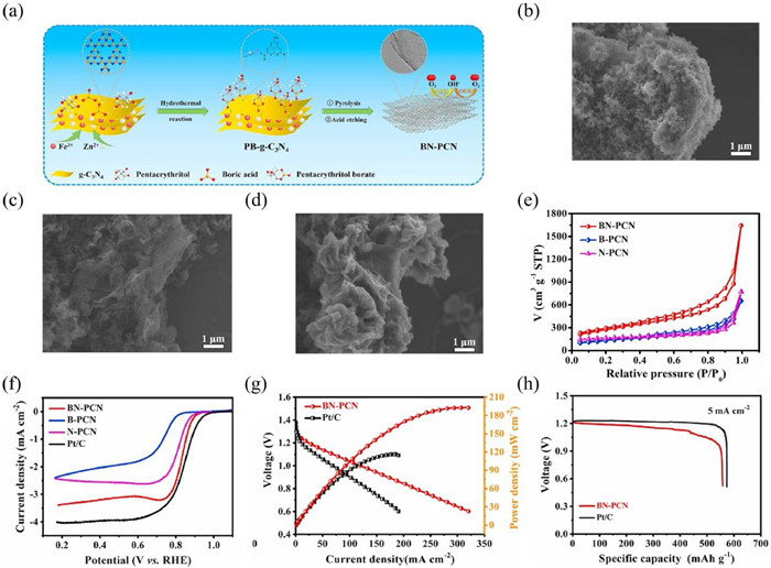
Recently, a B, N co-doped porous carbon nanosheet (BN-PCN) material was prepared as an ORR electrocatalyst for ZABs using a two-step carbonization-etching method (Fig. 9a) [105]. To demonstrate the role of B and N dual dopants, B-PCN and N-PCN were also prepared as contrast samples. As depicted in Figs. 9b-d, B-PCN show a nanorod-like structure, while N-PCN and BN-PCN exist in the form of nanosheets with multiple overlapped folds, which can be ascribed to the g-C3N4 template. Due to the different electronegativity of O and B atoms, B doping can promote the adsorption of intermediates, thus improving the ORR activity of BN-PCN. In addition, the strong interplay between B and N can optimize the electronic structure and provide rich structural defects, facilitating electron transfer and adsorption of oxygen intermediates. Additionally, the large SSA (966.46 m2/g) and high porosity can facilitate electrolyte diffusion (Fig. 9e). Benefiting from the above merits, the BN-PCN achieves superb ORR performance with a E1/2 of 0.84 V, superior to the Pt/C catalyst (Fig. 9f). The ZAB was further prepared by using the BN-PCN air cathode and Zn anode. The power density of the ZAB driven by the BN-PCN is 193.6 mW/cm2, about 1.6 times larger than the ZAB based on the Pt/C (Fig. 9g). A high specific capacity of 558.7 mAh/gZn and good energy density of 634.7 Wh/kgZn are also achieved with the BN-PCN cathode (Fig. 9h). When assembled into a ZAB, the battery can achieve a durable stability for about 100 h (~300 cycles). Moreover, it realizes higher energy efficiencies than the Pt/C-based ZAB, manifesting the splendid stability. The above results highlight the superiority of the BN-PCN for the ZABs.
B, N co-doped defective graphitic-carbon entangled Fe3C nanoparticles (D-BNGFe) was synthesized from natural biomass by high-temperature pyrolysis (Fig. 10a) [106]. For the preparation of the D-BNGFe, peanut shells were innovatively taken as the carbon source, and K3[Fe(CN)6] and NH3 as the N sources, boric acid as the B source. As displayed in Figs. 10b and c, the D-BNGFe is constituted by carbon sheet nanostructure with carbon-entangled Fe3C nanoparticles. The N element in D-BNGFe mainly exists in the form of pyridine N, which acts the active sites for ORR. Thanks to the low electronegativity of B dopants, the vacant 2pz orbitals in B atoms can conjugate with the carbon-π system, leading to the reduction of the O2 molecules at the positively charged B site. Thanks to the unique structure and rich B and N sites, the D-BNGFe catalyst exhibits excellent ORR activity with an initial potential of 0.95 V, 50 mV more negative than the Pt/C catalyst (Fig. 10d). Besides, after 10,000 cycles, the E1/2 shows only a small negative shift of 12 mV, indicating that the excellent stability of the D-BNGFe catalyst (Fig. 10e). Inspired by the outstanding behavior of the D-BNGFe catalyst, its applications in ZABs were further investigated (Fig. 10f). The constant discharge curves demonstrate the long-term stability of D-BNGFe, much better than the Pt/C and the reported non-precious cathode, reflecting the advantages of D-BNGFe in ZABs (Fig. 10g). Additionally, the ZAB assembled by D-BNGFe can achieve a stable cycle for more than 400 h, demonstrating its potential in practical applications.

To realize the bifunctionality, B, N, and F triple-doped lignin-based carbon porous nanofibers (BNF-LCFs) were synthesized by a two-step electrospinning and pyrolysis approach. In this strategy, biomass lignin, PVP, zinc borate, and ammonium fluoride were used as the precursors [63]. Thanks to the synergistic effects of B, N, and F heteroatoms and abundant defect sites, the BNF-LCFs catalyst showed satisfactory bifunctionality towards ORR and OER with a potential difference (ΔE) of 0.728 V. The liquid ZAB assembled with the BNF-LCFs delivers a large specific capacity of 791.5 mAh/g and excellent stability for about 600 cycles at 10 mA/cm2, which surpasses those of the Pt/C+RuO2. In addition, the solid ZABs also show excellent electrochemical properties and good mechanical flexibility. This work provides new ideas for the fabrication of cheap and efficient electrocatalysts for ZABs.
The above works highlight the significance of BNC materials in improving the energy density, power density, and cyclic stability of the ZABs. Compared to single doping, B and N dual doping exhibits unique advantages in improving electrical and electrochemical properties due to the synergistic interplay. It is believed that B and N dopants could enhance the electric conductivity and surface wettability. Furthermore, the B and N co-doping optimizes the electronic structure, introduces plentiful defects, and ensures enough sites, which are beneficial for the adsorption of oxygen intermediates and enhancing the ORR kinetics. However, it should be noted that most BNC materials show a single functionality towards ORR, while the OER performance is very poor. Hence, it is critical to develop bifunctional oxygen electrocatalysts by hybridizing BNC materials with other transition metal species, which is of significance to realize advanced rechargeable ZABs with high energy and power densities. Moreover, up to date, the reorganization of the active sites in BNC and a comprehensive comprehension of electronic interaction between BNC matrix and other transition metal sites are still lacking, which severely limit the development of BNC-based catalysts for ZABs.
As a newly emerging ZESD, ZHSCs that integrate the high power density of supercapacitors (SCs) and the high energy density of Zn-ion batteries have attracted extensive attention in the latest several years [15,107-111]. However, the electrochemical performance of ZHSCs is still restricted by the lack of efficient cathode materials. To enhance the adsorption of zinc ions and improve the electronic conductivity, various types of doped carbon materials have been successfully applied in the field [112-115].
Lu et al. made the first attempt to fabricate a layered B/N co-doped porous carbon (LDC) as the cathode material for ZHSCs [116]. The LDC is prepared by employing a simple intercalator-guided pyrolysis method, which includes self-assembly, pyrolysis, and deintercalation processes (Fig. 11a). SEM and TEM images reveal that the LDC is assembled by ultrathin nanosheets with wrinkled surfaces and porous structure (Figs. 11b and c). Energy dispersive spectroscopy (EDS) mapping image confirms the existence of C, N, B, and O elements (Fig. 11d). The dual doping of B/N heteroatoms is beneficial to prevent the stacking of carbon sheets, increase defects, provide more adsorption sites, and tailor the electronic feature, thus enabling efficient zinc-ion storage. Therefore, the quasi-solid Zn//gelatin/ZnSO4 (gel)//LDC ZHSC manifests fascinating performances, including good energy and power densities of 86.8 Wh/kg and 12.2 kW/kg, respectively, as well as long cyclic life as well as low self-discharge (Figs. 11e–g). Additionally, this ZHSC device maintains an excellent stability for 6500 cycles at 5 A/g with a capacity retention of 81.3%. This work demonstrates the feasibility of developing layered BNC materials for ZHSCs.

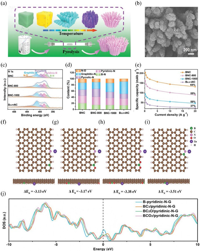
Recent studies have also proved that the incorporation of B and N into carbon materials can change the electronic structure and ameliorate the surface polarity, thus improving the capacity and rate performances of ZHSCs [112]. Despite great efforts in the synthesis of BNC materials for ZHSCs, the fundamental understanding of the active sites and the effect of doping type on the electrochemical performances are lacking. Recently, our group demonstrated that the B−N bonds play a key role in boosting Zn-ion storage [48]. A series of coralloidal BNCs were prepared by pyrolysis of urea, melamine, H3BO3, and Pluronic P123 (Figs. 12a and b). EDS mapping images confirm the existence of B, N, and C elements. By tailoring the contents of H3BO3, melamine, and calcination temperature, the BNC materials with different contents of B−N sites are prepared. As depicted in Figs. 12c and d, the content of the B−N bond in BNC is the highest. Therefore, a specific capacity of 204 mAh/g at 0.2 A/g is achieved with BNC, higher than those of the comparisons (Fig. 12e). An ultra-long cycle of 40,000 times with a Coulombic efficiency of 100% can be obtained by using BNC as the cathodic material. Density functional theory (DFT) calculations reveal that the B-pyridinic-N-G slab has a higher adsorption energy of Zn2+ ions of −3.51 eV, compared to other slabs (Figs. 12f–i). In addition, the B-pyridinic-N site can significantly enhance the electronic conductivity of graphene (Fig. 12j). These results offer a deeper understanding of the structure-property relationship of BNC in ZHSCs.
To increase the energy density, Han developed an alkaline aqueous ZHSC with a BNC cathode, a Zn anode, and KOH electrolyte [117]. The BNC material with a hierarchical pore structure and abundant defects was prepared by pyrolyzing metal-organic frameworks and H3BO3. Owing to the fast ion diffusion kinetics and charge transport, the optimized ZHSCs achieved a high energy density of 115.7 Wh/kg, outperforming most of the ZHSCs. At 10 A/g, a cycle of 10,000 times can be realized by the optimized ZHSC. This work opens a new path to enhance the electrochemical performance by constructing alkaline ZHSCs. Using spheroidizing growth of hydrothermal carbon as the drive force for assembly and melamine cyanurate nanosheets as the structure guide agent, B, N and O co-doped carbon flower (BCF) was fabricated as a superior cathodic material for ZHSCs [118]. The results showed that B/O dopants are favorable for the reversible absorption/desorption of electrolyte ions, while the presence of graphitic nitrogen sites can improve electron conductivity and offer rich defects for charge storage. Hence, the ZHSC assembled with BCF delivered a high specific capacity of 133.5 mAh/g at 1 A/g. Similarly, Li and coworkers developed B, N, and O modified ultrathin carbon nanobelts (CPTHB-Bx) for enhancing zinc-ion adsorption/desorption kinetics [119]. The CPTHB-Bx exhibited excellent rate performance with 98.5% capacitance retention after 10,000 cycles. These results all prove the synergistic role of B, N, and O co-doping in enhancing zinc-ion storage.
In summary, the incorporation of B and N dopants can promote the adsorption of zinc ions by providing sufficient zinc ion adsorption sites and changing the electronic structure. Meanwhile, B and N co-doping can improve the electronic conductivity and hydrophilicity of carbon materials, which is beneficial for charge storage. In addition, the introduction of B and N dopants can introduce the pseudocapacitive performance. Therefore, the energy density, power density, and cycle life of ZHSCs can be effectively enhanced with B/N dual doping (Table S2 in Supporting information). According to the latest work, B-pyridinic-N is the active site for zinc-ion adsorption [48]; however, how to precisely construct B-pyridinic-N active sites is still a challenge. Besides, more advanced BNC materials are urgently needed to be developed to improve the electrochemical performance of ZHSCs. Last but not the least, the role of B, N co-doping and the active sites of BNC in different electrolyte systems are worth further exploration.
BNC materials have been considered as a promising cathode material for the manufacture of high energy density and stable ZESDs. Previous reports have shown that B,N co-doping is conducive to increasing the electrochemically active surface area and improving the electronic conductivity, which are conducive to charge transfer and storage. Additionally, B,N co-doping enhances the wettability of carbon materials, which promotes the electrode-electrolyte contact. Significantly, various functional groups containing B and N can be introduced into carbon materials, and also the electronic structure of carbon sites can be effectively regulated, which are beneficial to ion/reactant adsorption and charge transfer. In this review, we provide a comprehensive summary of the synthesis and applications of BNC materials in ZESDs. Despite the great achievements that have been made, the large-scale synthesis, precise regulation of the BNC materials, as well as mechanism understanding remain major challenges, which hinder their development. The challenges faced by BNC materials can be concluded as follows:
(1) Although various synthetic methods for BNC materials have been adopted, the large-scale synthesis and precise control of the doping amount and doping types of B and N remain great challenges. Furthermore, although the combination of multiple strategies may be advantageous to achieve novel performances while simultaneously satisfying the characteristics of high efficiency, environmental friendliness, ease of operation, and energy saving, it is difficult to master the formation mechanism of BNC materials in such a complex system.
(2) Most of the BNC materials show only a single functionality towards ORR. However, when considering practical applications, how to realize bi-functionality towards ORR and OER is of great significance. In this regard, intelligent hybridization of BNC materials with other active species intelligently may be a fascinating option. However, due to the uncertainty of the doping locations of boron and nitrogen atoms, more efforts should be devoted to understanding the synergistic effect of dual doping, the interaction between BNC support, other species, and the active sites for electrocatalytic reactions.
(3) To date, the dynamic changes of active sites in BNC materials are not well understood. Thereby, precise monitoring of the changes of active sites during the charge and discharge process is helpful for further understanding of the energy storage mechanism, which can contribute to the rational design of advanced BNC materials.
(4) For a long time, the development of ZESDs has been plagued with various problems, such as competitive hydrogen evolution, dendrite, self-corrosion. Regulation of zinc anodes has been proved to be an effective strategy to improve battery performance. However, existing research on BNC materials still concentrates on improving the performance of cathode materials. Therefore, it is of great prospect for future exploration on BNC-based materials to regulate the Zn2+ migration process and inhibit zinc dendrites. More importantly, the working mechanism is urgently needed to uncover.
The authors declare that they have no known competing financial interests or personal relationships that could have appeared to influence the work reported in this paper.
Hangwen Zheng: Writing – original draft, Formal analysis, Data curation. Ziqian Wang: Writing – original draft, Formal analysis, Data curation. HuiJie Zhang: Writing – original draft, Formal analysis, Data curation. Jing Lei: Investigation, Formal analysis. Rihui Li: Validation, Formal analysis. Jian Yang: Writing – review & editing, Supervision, Funding acquisition, Conceptualization. Haiyan Wang: Writing – review & editing, Supervision, Funding acquisition, Formal analysis, Conceptualization.
This work was financially supported by the National Natural Science Foundation of China (No. 22302177), and the Public Technology Application Project of Jinhua City (No. 2022–4-067), and the Self Designed Scientific Research of Zhejiang Normal University (No. 2021ZS0604).
Supplementary material associated with this article can be found, in the online version, at doi:
Y. Liu, X. Lu, F. Lai, et al., Joule 5 (2021) 2845–2903. doi: 10.1016/j.joule.2021.10.011
P. Ye, K. Fang, H. Wang, et al., Nat. Commun. 15 (2024) 1012. doi: 10.1038/s41467-024-45320-0
H. Zhang, K. Fang, J. Yang, et al., Coord. Chem. Rev. 506 (2024) 215723. doi: 10.1016/j.ccr.2024.215723
J. Xiao, F. Shi, T. Glossmann, C. Burnett, Z. Liu, Nat. Energy 8 (2023) 329–339. doi: 10.1038/s41560-023-01221-y
Y. Wu, X. Huang, L. Huang, J. Chen, Energy Environ. Mater. 4 (2021) 19–45. doi: 10.1002/eem2.12088
L. Sun, Y. Liu, R. Shao, et al., Energy Storage Mater. 46 (2022) 482–502. doi: 10.1016/j.ensm.2022.01.042
F.Y. Li, X.L. Hu, Batter. Supercaps 4 (2021) 389–406. doi: 10.1002/batt.202000243
J.F.F. Gomez, N. Oli, S. Chang, et al., ACS Appl. Energy Mater. 7 (2024) 2048–2056. doi: 10.1021/acsaem.4c00008
H. Chen, X. Li, K. Fang, et al., Adv. Energy Mater. 13 (2023) 2302187. doi: 10.1002/aenm.202302187
C. Tian, H. Wang, L. Xie, Y. Zhong, Y. Hu, Adv. Energy Mater. 14 (2024) 2400276. doi: 10.1002/aenm.202400276
C. Tian, J. Wang, R. Sun, et al., Angew. Chem. Int. Ed. 62 (2023) e202310970. doi: 10.1002/anie.202310970
L. Yan, B. Xie, C. Yang, et al., Adv. Energy Mater. 13 (2023) 2204245. doi: 10.1002/aenm.202204245
Z. Xu, L. Yan, J. Shen, et al., Sci. China Technol. Sci. 65 (2022) 693–703. doi: 10.1007/s11431-021-1942-6
Y. Yang, D. Chen, H. Wang, et al., Chem. Eng. J. 431 (2022) 133250. doi: 10.1016/j.cej.2021.133250
H. Wang, W. Ye, Y. Yang, Y. Zhong, Y. Hu, Nano Energy 85 (2021) 105942. doi: 10.1016/j.nanoen.2021.105942
L. Li, S. Jia, M. Cao, et al., Chin. Chem. Lett. 34 (2023) 108307. doi: 10.1016/j.cclet.2023.108307
Z.J. Chen, T.Y. Shen, M.H. Zhang, et al., Adv. Funct. Mater. 34 (2024) 2314864. doi: 10.1002/adfm.202314864
Y. Feng, Y. Wang, L. Sun, et al., Small 19 (2023) 2302650. doi: 10.1002/smll.202302650
J. Wei, P. Zhang, T. Shen, et al., ACS Energy Lett. 8 (2023) 762–771. doi: 10.1021/acsenergylett.2c02646
W. Lu, C. Zhang, H. Zhang, X. Li, ACS Energy Lett. 6 (2021) 2765–2785. doi: 10.1021/acsenergylett.1c00939
K. Zhang, Q. Yu, J. Sun, Z. Tie, Z. Jin, Adv. Mater. 36 (2024) 2309838. doi: 10.1002/adma.202309838
L. Ma, G. Zhu, Z. Wang, et al., Nano Lett. 23 (2023) 5272–5280. doi: 10.1021/acs.nanolett.3c01310
Q. Li, D.H. Wang, B.X. Yan, et al., Angew. Chem. Int. Ed. 61 (2022) e202202780. doi: 10.1002/anie.202202780
X. Li, Y. Sun, L. Zhou, et al., Mater. Horiz. 11 (2024) 4133–4143. doi: 10.1039/d4mh00544a
W.J. Fan, J.Y. Wu, H.L. Wang, Mater. Res. Lett. 11 (2023) 481–516. doi: 10.1080/21663831.2023.2178860
M. Xue, J. Bai, M. Wu, et al., Energy Storage Mater. 62 (2023) 102940. doi: 10.1016/j.ensm.2023.102940
S. Ding, Q. Chen, S. Chen, Y. Tian, J. Zhang, Chin. Chem. Lett. 34 (2023) 108232. doi: 10.1016/j.cclet.2023.108232
N. Yang, L. Ji, H. Fu, et al., Chin. Chem. Lett. 33 (2022) 3961–3967. doi: 10.1016/j.cclet.2022.03.037
N. Zhang, J.C. Wang, Y.F. Guo, et al., Coord. Chem. Rev. 479 (2023) 215009. doi: 10.1016/j.ccr.2022.215009
J. Luan, H. Yuan, J. Liu, C. Zhong, Energy Storage Mater. 66 (2024) 103206. doi: 10.1016/j.ensm.2024.103206
B. Sambandam, V. Mathew, S. Kim, et al., Chem 8 (2022) 924–946. doi: 10.1016/j.chempr.2022.03.019
X. Chen, J.H. Liu, H. Jiang, et al., Energy Storage Mater. 65 (2024) 103168. doi: 10.1016/j.ensm.2023.103168
Y. Zeng, X.F. Lu, S.L. Zhang, et al., Angew. Chem. Int. Ed. 60 (2021) 22189–22194. doi: 10.1002/anie.202107697
Y.R. Ji, Y.F. Guo, X. Liu, P.F. Wang, T.F. Yi, Chem. Eng. J. 471 (2023) 144743. doi: 10.1016/j.cej.2023.144743
Q.C. Zhu, M.Y. Cheng, B.W. Zhang, et al., Adv. Funct. Mater. 29 (2019) 1905979. doi: 10.1002/adfm.201905979
L. Xie, W. Xiao, X. Shi, et al., Chem. Commun. 58 (2022) 13807–13810. doi: 10.1039/d2cc04431e
Y. Kim, Y. Park, M. Kim, et al., Nat. Commun. 13 (2022) 2371. doi: 10.1038/s41467-022-29987-x
Y. Wang, S. Sun, X. Wu, H. Liang, W. Zhang, Nano-Micro Lett. 15 (2023) 78. doi: 10.1007/s40820-023-01065-x
W. Fan, J. Wu, H. Wang, Mater. Res. Lett. 11 (2023) 481–516. doi: 10.1080/21663831.2023.2178860
Y. Li, R. Ding, Z. Jia, et al., Energy Storage Mater 57 (2023) 334–345. doi: 10.3390/foods12020334
X. Liu, C. Wang, J. Meng, et al., Chin. Chem. Lett. 34 (2023) 108745. doi: 10.1016/j.cclet.2023.108745
K. Gao, B. Wang, L. Tao, et al., Adv. Mater. 31 (2019) 1805121. doi: 10.1002/adma.201805121
W. Lu, B.B. Xie, C. Yang, et al., Small 19 (2023) 2302629. doi: 10.1002/smll.202302629
F. Xiao, Z. Lin, J. Zhang, et al., Energy Storage Mater. 41 (2021) 61–68. doi: 10.1117/12.2604785
D. Wu, F. Sun, Z. Qu, et al., J. Mater. Chem. A 10 (2022) 17225–17236. doi: 10.1039/d2ta04194d
A.K. Thakur, K. Kurtyka, M. Majumder, et al., Adv. Mater. Interfaces 9 (2022) 2101964. doi: 10.1002/admi.202101964
C.L. Zhu, H.L. Wang, W.J. Fan, et al., Rare Met. 41 (2022) 2505–2516. doi: 10.1007/s12598-022-01975-6
X. Chen, P. Ye, H. Wang, et al., Adv. Funct. Mater. 33 (2023) 2212915. doi: 10.1002/adfm.202212915
L. Huang, Z. Luo, W. Han, et al., Nano Res. 15 (2022) 5769–5774. doi: 10.1007/s12274-022-4201-1
W. Zhang, J. Yin, W. Jian, et al., Nano Energy 103 (2022) 107827. doi: 10.1016/j.nanoen.2022.107827
J. Liu, W. Guo, H. Tao, et al., Chem. Eng. J. 471 (2023) 144544. doi: 10.1016/j.cej.2023.144544
M. Kim, X. Xu, R. Xin, et al., ACS Appl. Mater. Interfaces 13 (2021) 52034–52043. doi: 10.1021/acsami.1c09107
L. Shi, J.W. Ye, H. Lu, et al., Chem. Eng. J. 410 (2021) 128365. doi: 10.1016/j.cej.2020.128365
J. Hao, J.M. Wang, S. Qin, et al., J. Mater. Chem. A 6 (2018) 8053–8058. doi: 10.1039/c8ta00683k
B. Chen, Z. Qi, B. Chen, et al., Angew. Chem. Int. Ed. 63 (2024) e202316116. doi: 10.1002/anie.202316116
K. Yuan, T.J. Gao, Y. Yang, et al., Rare Met. 42 (2023) 2643–2657. doi: 10.1007/s12598-023-02263-7
X. Sun, X. Gao, Z. Li, et al., Small Methods 8 (2024) 2300746. doi: 10.1002/smtd.202300746
M. Guo, H. Zhang, L. Luo, et al., Carbon 217 (2024) 118631. doi: 10.1016/j.carbon.2023.118631
L. Zhang, K. Huang, P. Wen, et al., Energy Storage Mater. 42 (2021) 430–437. doi: 10.1016/j.ensm.2021.07.041
B. Yan, J. Zheng, F. Wang, et al., Mater. Des. 201 (2021) 109518. doi: 10.1016/j.matdes.2021.109518
Y. Xiang, L. Lu, A.G.P. Kottapalli, Y. Pei, Carbon Energy 4 (2022) 346–398. doi: 10.1002/cey2.185
Q. Wu, M.M. Gao, G.Y. Zhang, et al., Nanotechnology 30 (2019) 185702. doi: 10.1088/1361-6528/ab0042
H. Tabassum, C. Qu, K.T. Cai, et al., J. Mater. Chem. A 6 (2018) 21225–21230. doi: 10.1039/c8ta08590k
J. Du, Y. Zhang, H. Lv, A. Chen, J. Colloid Interface Sci. 587 (2021) 780–788. doi: 10.1016/j.jcis.2020.11.037
T. Sun, J. Wang, C. Qiu, et al., Adv. Sci. 5 (2018) 1800036. doi: 10.1002/advs.201800036
Y. Zhang, X.D. Zhuang, Y.Z. Su, F. Zhang, X.L. Feng, J. Mater. Chem. A 2 (2014) 7742–7746. doi: 10.1039/c4ta00814f
X.F. Wang, C. Han, H.T. Li, et al., Nano Res. 16 (2023) 290–298. doi: 10.1007/s12274-022-4786-4
J.B. Wang, Z. Ren, Y. Hou, et al., New Carbon Mater. 35 (2020) 193–208. doi: 10.1016/S1872-5805(20)60484-X
J. Wang, T. Fan, J. Lu, et al., Int. J. Min. Met. Mater. 29 (2022) 136–143. doi: 10.1007/s12613-021-2302-6
S. Ullah, Y. Liu, M. Hasan, et al., Nano Res. 15 (2022) 1310–1318. doi: 10.1007/s12274-021-3655-x
M.I. Kairi, M. Khavarian, S. Abu Bakar, B. Vigolo, A.R. Mohamed, J. Mater. Sci. 53 (2018) 851–879. doi: 10.1007/s10853-017-1694-1
P. Sun, J. Huang, F. Xu, et al., ACS Appl. Mater. Interfaces 12 (2020) 28075–28082. doi: 10.1021/acsami.0c02535
Y. Wen, H. Zhu, J. Hao, et al., Appl. Catal. B: Environ. 292 (2021) 120144. doi: 10.1016/j.apcatb.2021.120144
J. Xu, Z. Li, P. Sun, et al., Carbon 155 (2019) 379–385. doi: 10.1016/j.carbon.2019.08.088
J.Y. Sun, Y.B. Chen, M.K. Priydarshi, et al., Adv. Mater. 28 (2016) 10333–10339. doi: 10.1002/adma.201602247
H. Luan, K. Liu, Y.H. Zhou, J.C. Sun, Ionics 28 (2022) 4997–5004 (Kiel).
L. Liu, X. Zhang, D. Zhang, et al., Chem. Eng. J. 473 (2023) 145454. doi: 10.1016/j.cej.2023.145454
Y. Pei, H. Song, Y. Liu, et al., J. Colloid Interface Sci. 600 (2021) 865–871. doi: 10.1016/j.jcis.2021.05.089
G.Q. Ma, M. Cheng, Ferroelectrics 536 (2018) 181–186. doi: 10.1080/00150193.2017.1391595
N. Gnanaseelan, L. Marasamy, A. Mantilla, et al., Int. J. Hydrog. Energy 47 (2022) 40905–40919. doi: 10.1016/j.ijhydene.2022.08.234
J.J. Yao, C. Liu, J.Y. Li, et al., Rare Met. 42 (2023) 2307–2323. doi: 10.1007/s12598-023-02265-5
Y. Wang, R. Gan, S. Zhao, et al., Appl. Surf. Sci. 598 (2022) 153891. doi: 10.1016/j.apsusc.2022.153891
M.J. Zhang, Y. Duan, C. Yin, et al., Sci. Adv. 6 (2020) eabd9472. doi: 10.1126/sciadv.abd9472
M. Khan, J. Zhai, W. Su, et al., ChemPhysMater 2 (2023) 207–216. doi: 10.1016/j.chphma.2022.08.001
L. Luo, Y. Zhou, W. Yan, et al., Electrochim. Acta 360 (2020) 137010. doi: 10.1016/j.electacta.2020.137010
G. Yang, S.J. Park, Materials 12 (2019) 1177. doi: 10.3390/ma12071177
D. Ji, Y. Lin, X. Guo, et al., Nat. Rev. Methods Prim. 4 (2024) 1. doi: 10.1038/s43586-023-00278-z
Y. Wang, X. Ge, Q. Lu, et al., Nat. Commun. 14 (2023) 6968. doi: 10.1038/s41467-023-42728-y
F. Sun, Z.B. Qu, J.H. Gao, et al., Adv. Funct. Mater. 28 (2018) 1804190. doi: 10.1002/adfm.201804190
Z. Feng, Z. Geng, S. Pan, et al., Appl. Catal. B: Environ. Energy 353 (2024) 124101. doi: 10.1016/j.apcatb.2024.124101
R. Yuge, S. Bandow, M. Yudasaka, et al., Carbon 111 (2017) 675–680 N Y.
Z. Chen, L. Hou, Y. Cao, Y. Tang, Y. Li, Appl. Surf. Sci. 435 (2018) 937–944. doi: 10.1016/j.apsusc.2017.11.159
Q. Xia, H. Yang, M. Wang, et al., Adv. Energy Mater. 7 (2017) 1701336. doi: 10.1002/aenm.201701336
R. Su, X. Tao, K. Zheng, et al., Carbon 225 (2024) 119125. doi: 10.1016/j.carbon.2024.119125
Y. Dai, H. Li, C. Wang, et al., Nat. Commun. 14 (2023) 3382. doi: 10.1038/s41467-023-39048-6
L. Yan, J. Chen, C. Yang, J. Ning, Y. Hu, Small Sci. 4 (2024) 2300094. doi: 10.1002/smsc.202300094
J.N. Liu, C.X. Zhao, J. Wang, et al., Energy Environ. Sci. 15 (2022) 4542–4553. doi: 10.1039/d2ee02440c
W.F. Wu, X. Yan, Y. Zhan, Chem. Eng. J. 451 (2023) 138608. doi: 10.1016/j.cej.2022.138608
Q. Wang, S. Kaushik, X. Xiao, Q. Xu, Chem. Soc. Rev. 52 (2023) 6139–6190. doi: 10.1039/d2cs00684g
Y. Li, P. Peng, Z.J. Liao, et al., ACS Sustain. Chem. Eng. 8 (2020) 3728–3733. doi: 10.1021/acssuschemeng.9b06840
Y. Ren, P. Ye, J. Chen, et al., J. Power Sources 545 (2022) 231908. doi: 10.1016/j.jpowsour.2022.231908
H. Wang, Y. Jiao, S. Wang, et al., Small 17 (2021) 2103517. doi: 10.1002/smll.202103517
L. Yan, H. Wang, J. Shen, et al., Chem. Eng. J. 403 (2021) 126385. doi: 10.1016/j.cej.2020.126385
R. Zhao, Q. Li, Z. Chen, et al., Carbon 164 (2020) 398–406. doi: 10.1016/j.carbon.2020.04.019
Y. Kang, W. Wang, J. Li, et al., J. Power Sources 493 (2021) 229665. doi: 10.1016/j.jpowsour.2021.229665
G. Zhang, X. Liu, L. Wang, et al., ACS Sustain. Chem. Eng. 7 (2019) 19104–19112. doi: 10.1021/acssuschemeng.9b05033
P.G. Liu, Y. Gao, Y.Y. Tan, et al., Nano Res. 12 (2019) 2835–2841. doi: 10.1007/s12274-019-2521-6
H. Wang, X. Chen, J. Zhang, et al., Appl. Surf. Sci. 598 (2022) 153819. doi: 10.1016/j.apsusc.2022.153819
Z. Xu, Z. Sun, J. Shan, et al., Adv. Funct. Mater. 14 (2023) 2302818.
S. Chen, Z. Xiang, Z. Xiao, et al., Nano Res. 16 (2023) 6922–6932. doi: 10.1007/s12274-023-5468-6
Y. Liu, S. Zheng, J. Ma, et al., Adv. Energy Mater. 12 (2022) 2200341. doi: 10.1002/aenm.202200341
H. Zhang, Y. Zhang, L.M. Zhang, et al., J. Alloys Compd. 969 (2023) 172407. doi: 10.1016/j.jallcom.2023.172407
J. Yu, X. Jia, J. Peng, et al., ACS Appl. Energy Mater. 6 (2023) 2728–2738. doi: 10.1021/acsaem.2c03311
F. Shi, Q. Liu, C. Yang, J. Qiu, L. Zang, Adv. Sustain. Syst. 7 (2023) 2200412. doi: 10.1002/adsu.202200412
J. Yao, F. Li, R. Zhou, et al., Chin. Chem. Lett. 35 (2024) 108354. doi: 10.1016/j.cclet.2023.108354
Y. Lu, Z. Li, Z. Bai, et al., Nano Energy 66 (2019) 104132. doi: 10.1016/j.nanoen.2019.104132
L. Han, X. Zhang, J. Li, et al., J. Colloid Interface Sci. 599 (2021) 556–565. doi: 10.1016/j.jcis.2021.04.114
H.L. Fan, X. Hu, S. Zhang, et al., Carbon 180 (2021) 254–264. doi: 10.1016/j.carbon.2021.04.093
Y.Y. Li, J.J. Huang, L.Q. Kang, et al., Sci. China Mater. 65 (2022) 1495–1502. doi: 10.1007/s40843-021-1923-6

Figure 2 (a) Preparation process of the ACC@BCN. (b, c) Scanning electron microscope (SEM) images of the ACC and (d, e) ACC@BNC. (f) Galvanostatic charge and discharge (GCD) profiles. Reproduced with permission [53]. Copyright 2020, Elsevier. (g) SEM of the B/N-CNS. (h) Transmission electron microscope (TEM) image, (i) N2 adsorption/desorption isotherms, and (j) specific capacitances of the B/N-CNS. Reproduced with permission [54]. Copyright 2018, Royal Society of Chemistry.

Figure 3 (a) Preparation process of the N/B-OMC. TEM images of the (b, c) OMC and (d, e) N/B-OMC. (f) Pore size distributions of the OMC and N/B-OMC. Reproduced with permission [64]. Copyright 2020, Elsevier.

Figure 4 (a) Preparation process of the B,N-carbon. SEM images of the (b) Zn-based template and (c) B,N-carbon. (d) Linear sweep voltammetry (LSV) curves. Reproduced with permission [65]. Copyright 2018, Wiley-VCH. (e) Preparation process of G-CBP-a. Reproduced with permission [66]. Copyright 2014, Royal Society of Chemistry. (f) Preparation process of the B,N@C nanocages. Reproduced with permission [67]. Copyright 2022, Tsinghua University Press.

Figure 5 (a) Preparation process of the TDC-B. (b) N 1s and (c) B 1s XPS spectra of the different TDC-B samples. (d) GCD curves at 1 A/g. (e) Cycling performance of the TDC-B-0.50. Reproduced with permission [72]. Copyright 2020, American Chemical Society.

Figure 6 (a) N 1s XPS spectra. (b) Simulated model of the GNB. Reproduced with permission [80]. Copyright 2022, Elsevier. (c) The preparation process, (d, e) SEM images of the N,B-CQDs/rGO composite. (f) N2 adsorption–desorption isotherms, (g) pore size distributions, and (h) rate performances of different samples. Reproduced with permission [81]. Copyright 2023, Youke Publishing Co., Ltd. (i) Preparation process of the BNF-LCFs. (j) ORR and oxygen evolution reaction (OER) LSVs. Reproduced with permission [82]. Copyright 2022, Elsevier.

Figure 7 (a) SEM image and (b) magnified TEM image of the BN-SWCNHs. (c) Raman spectra. (d) N 1s XPS spectra of the N-SWNCHs and BN-SWCNHs, and (e) B 1s XPS spectra of the B-SWCNHs and BN-SWCNHs. Reproduced with permission [91]. Copyright 2017, Elsevier. (f) SEM images of the BNC. (g) N2 adsorption-desorption isotherms, (h) the pore size distribution, and (i) Raman spectra of the different samples. Reproduced with permission [92]. Copyright 2018, Elsevier.

Figure 8 (a) Preparation, (b) SEM, and (c) survey spectrum of the BN/C nanosheets. (d) LSV curves in O2-saturated 0.1 mol/L KOH. (e) LSV curves before and after cycling. (f) Open circuit voltages, (g) discharge polarization curves and power density curves, (h) cycling stability of the liquid ZABs. (i) Open circuit voltage and (j) cycling stability under bending of the solid-state ZAB. Reproduced with permission [104]. Copyright 2020, Elsevier.

Figure 9 (a) Preparation process of the BN-PCN. SEM images of the (b) B-PCN, (c) N-PCN, and (d) BN-PCN. (e) Nitrogen adsorption-desorption isotherms. (f) ORR polarization curves of different samples at 5 mV/s. (g) The discharge polarization curves and power densities and (h) specific capacities of the BN-PCN and Pt/C catalysts at 5 mA/cm2. Reproduced with permission [105]. Copyright 2021, Elsevier.

Figure 10 (a) Preparation process, (b) TEM and (c) high-resolution TEM images of the D-BNGFe. (d) Polarization curves. (e) LSV curves of the D-BNGFe before and after 10,000 cycles. (f) Schematic diagram of the liquid ZABs. (g) Discharge curves at 10 mA/cm2. Reproduced with permission [106]. Copyright 2019, American Chemical Society.

Figure 11 (a) Preparation process, (b) SEM image, and (c) TEM image of the LDC. (d) EDS mapping images of C, B, N, and O in the LDC. (e) Ragone plot of the quasi-solid ZHSC. (f) Cycling behavior and coulombic efficiency of the LDC-based ZHSC. (g) Self-discharge performance. Reproduced with permission [116]. Copyright 2019, Elsevier.

Figure 12 (a) Preparation process and (b) SEM image of the BNC nano-bundles. (c) N 1s XPS spectra, (d) different contents of N species, and (e) specific capacities of the BC, BNC, and BN. (f-i) Theoretical calculation models and ΔEa of Zn atom adsorbed on different models. (j) PDOSs of the different models. Reproduced with permission [48]. Copyright 2023, Wiley-VCH.

 扫一扫看文章

扫一扫关注我们
 DownLoad:

 下载:
下载: