Figure 1.
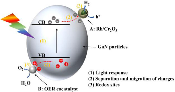
A proposed reaction mechanism of water splitting on GaN particles photocatalyst modified with dual-cocatalysts under the visible light.
Wafer-level GaN-based nanowires photocatalyst for water splitting
Kun Wang , Jiaxuan Qiu , Zefei Wu , Yang Liu , Yongqi Liu , Xiangpeng Chen , Bao Zang , Jianmei Chen , Yunchao Lei , Longlu Wang , Qiang Zhao

With population growth and economic development, global energy demand is on the rise. However, conventional fossil energy sources like coal, oil, and gas are non-renewable and finite. Also, excessive use of fossil fuels can cause severe issues such as climate degradation or environmental contamination [1-3]. Hydrogen is widely recognized as a renewable and clean energy source and offers an alternative to fossil fuels [4-8]. The photocatalytic hydrogen evolution reaction (PHER), which is based on semiconductor photocatalysts, is a straightforward and promising method to produce hydrogen [9-15].
Photoelectrochemical (PEC) devices have been reported to be used in the hydrogen production from overall water splitting (OWS) [16-25]. Employing additional bias or sacrificial reagents, the PEC can achieve a notably high solar-to-hydrogen (STH) conversion efficiency [26-31]. However, as the reaction time advances, electrode corrosion and depletion of sacrificial reagent become the primary obstacles to maintaining effective water splitting over an extended period using PEC [32]. Additionally, the usage of additional bias or sacrificial reagents escalates the cost of hydrogen production. The photocatalytic (PC) water splitting system eliminates the need for electrical wire, bias and conductive electrolyte, reducing system costs and addressing photocatalyst corrosion, stability and safety issues, unlike PEC [33,34]. Among the currently known photocatalysts, group Ⅲ-nitride semiconductors, such as Ga(In)N, possess energy bandgaps that cover a wide absorption range nearly the entire solar spectrum, making them promising for highly efficient overall water splitting. Moreover, their surfaces can be tailored to be nitrogen-rich [35], offering protection against photocorrosion and oxidation and ensuring stability in photocatalysis. Compared to conventional semiconductor particle photocatalyst systems, the wafer-level GaN NWs photocatalyst system, in which GaN nanowires are grown on a Si substrate using radio frequency plasma-assisted molecular beam epitaxy (MBE), is easy to implement and be reused, and has low costs of raw materials. Additionally, it exhibits higher resistance to light intensity, greater long-term stability, and has achieved the highest STH efficiency in overall water splitting [36-38]. To date, GaN NWs photocatalytic splitting pure water has achieved a high STH ~9.2%, which is the highest value ever reported. And the origin elements required for it are relatively low in price due to their abundant reserves on earth. More importantly, the GaN NWs photocatalyst can perform stable and efficient water splitting for a long-term using simulated seawater. It has potential to be a fabulous candidate for the application in the field of PHER from seawater splitting.
In this review, we first introduce the fundamentals of GaN photocatalysis for HER. And then strategies such as designing quadruple-band InGaN nanowires, controlling the near-surface band bending, loading dual-cocatalysts, and optimizing the temperature for improving GaN NWs photocatalytic OWS performance are systematically summarized. Furthermore, some of the essential conditions for advancing its large-scale industry-friendly application are discussed in detail. Finally, we outline the future work directions for the industrialization of GaN NWs photocatalyst in seawater splitting for hydrogen production, with a focus on its potential contribution to addressing the global energy crisis.
There are various factors that affect the performance of particles photocatalyst for water splitting, including (1) light response, (2) separation and migration of charge carries, and (3) the presence of redox sites on the surface of photocatalysts, which all impact the efficiency of the photocatalytic hydrogen evolution reaction in varying degrees [39]. To improve photocatalytic performance, it is necessary to focus on enhancing light absorption, improving separation of charge carries, and facilitating hydrogen evolution reaction (HER) and oxygen evolution reaction (OER), respectively.
The intrinsic bandgap of GaN is 3.4 eV. Additionally, the strategies, such as p-type metal doping, material composite, and structural modulation can regulate its bandgap. To extend the edge of light absorption, composite materials are being considered for development. For particulate photocatalyst, Kazuhiko et al. reported a solid solution of GaN and ZnO (GaN:ZnO), in which different percentages of Zn atoms can extend the visible-light absorption edge, thus enabling hydrogen production through water splitting under visible light [40,41]. The bandgap of GaN:ZnO is smaller than that of either single GaN or ZnO, which is conducive to water splitting [42]. Moreover, its inherent built-in electric field can facilitate the separation and transport of charge carriers, thereby reducing reverse reactions.
One effective way to enhance the efficiency of solar water-splitting hydrogen production is through the reduction and oxidation of electrons and holes respectively under photoexcitation, which largely relies on the function of cocatalysts [43-45]. Kazuhiko et al. reported that core/shell-structured Rh/Cr2O3 nanoparticles (NPs) is a great strategy as HER promoters of visible light water splitting [46]. The primary benefit of these core/shell nanoparticles is the ability of the Cr2O3 shell to impede oxygen while allowing the passage of protons and H2 molecules, thereby inhibiting the reverse reaction of hydrogen–oxygen recombination. To further improve the efficiency of hydrogen production from solar-driven water splitting, loading dual-cocatalysts for both the HER and OER to the same photocatalyst to overcome the inefficiencies caused by the lack of H2 and O2 active sites on most photocatalysts. A reaction mechanism for visible light-driven overall water splitting is illustrated in Fig. 1, where A (Rh/Cr2O3) acts as H2 evolution promoters and B (Mn3O4, Co3O4, etc.) functions as O2 evolution cocatalysts. The modification of dual-cocatalysts separates the HER and OER sites in space, and further reduces the recombination of charge carriers. In brief, these strategies have all promoted the development of catalysts in the field of photocatalysis
Although the STH conversion efficiency obtained from traditional semiconductor particles GaN photocatalyst systems appears to have plateaued, the STH of GaN NWs photocatalytic system has rapidly advanced in recent years [47-54]. This progress is attributed to the implementation of various strategies that have been widely reported, resulting in a significant improvement and reaching new levels of performance [55-59]. Next, the focus is on discussing GaN NWs photocatalytic system. And a detailed introduction is given on its advantages of this system and dedicated strategies for performance improvement.
There are two main types of semiconductor particles photocatalyst systems: suspension photocatalyst system and powder photocatalyst system. The suspension of semiconductor particles photocatalyst system (Fig. 2a) requires stirring to ensure sufficient light absorption and photocatalytic efficiency [60,61]. And as the reaction time progresses, photocatalyst particles would gradually sink and aggregate at the bottom of the liquid solution resulting in a rapid decline in its performance, which is the main reason why it cannot undergo reactions for a long time. Semiconductor particles can also be coated onto the wafer, as shown in Fig. 2b [62,63]. However, semiconductor particles would detach during the process of overall water splitting, rendering long-term and efficient overall water splitting unfeasible.

Nanowire arrays grown on Si substrates using MBE have addressed these issues [64-66]. Fig. 2c shows the scheme of wafer-level GaN-based nanowire arrays photocatalytic overall water splitting system [67]. And the excellent uniformity of GaN NWs photocatalyst nanowires grown on Si substrate by MBE is presented in Fig. 2d [68]. More noteworthy, the wafer-level GaN NWs photocatalyst is capable of efficient overall water splitting for a long-term while maintaining structural stability without the use of bias or sacrificial agents. Accordingly, the nanowires photocatalytic system based on GaN using MBE shows the potential of being adopted as a considerable hydrogen production method on an industrial scale.
Strategies such as core/shell-structured and loading dual-cocatalysts, for improving conventional GaN particle photocatalysts also have been applied to GaN NWs photocatalyst. For this nanowires arrays system, there are also distinctive strategies to improve performance.
To achieve efficient overall water splitting, photocatalysts should have a narrow bandgap to absorb light effectively and appropriate band edge positions for proton oxidation and water reduction reactions. However, it is impossible for most of conventional metal oxides (GaAs, InP, etc.) to possess a suitable band edge position [69,70]. In contrast, GaN has relatively narrow bandgap and exhibits a broad light absorption range covering nearly the entire solar spectrum, with band edge positions that can straddle the water oxidation and reduction potentials. The bandgap of GaN can be modified by incorporating an appropriate amount of indium doping [71]. Previously reported single GaN or dual-band InGaN nanostructures had low solar-to-hydrogen conversion efficiency due to limitations in indium doping, resulting in a larger bandgap and restricted absorption of specific solar photon ranges [72].
To improve light absorption, Wang et al. designed a quadruple-band InGaN nanowire structure grown on a non-planar silicon substrate, as shown in the Fig. 3a [73]. As the indium doping concentration increases, the bandgap of InGaN decreases. When indium doping reaches 35%, the bandgap of InGaN ultimately could decreases to 2.1 eV. By varying the indium doping concentration, the bandgap of InGaN can be turned from 3.4 eV to 2.1 eV, enabling absorption of solar photons up to nearly 600 nm. Photoluminescence (PL) spectra analysis reveals that increasing indium doping led to larger emission peaks. Fig. 3b shows the bandgap of InGaN with different indium doping compositions. The wide emission spectrum of the quadruple-band nanowire structure demonstrates its superior light absorption capability within the wavelength range of 370–580 nm compared to individual single-band segments (Fig. 3c).

Furthermore, the use of a non-planar silicon substrate can improve hydrophilicity, facilitating enhanced contact between water molecules and the InGaN photocatalyst. Nanowire arrays grown on planar surfaces only expose one side to sunlight irradiation, as a result, the light-receiving area of the nanowires is limited. As shown in Figs. 3d and e, SEM images of the flower-shaped InGaN nanowire structure grown on nonplanar Si substrates can achieve maximum exposure of side surfaces to light, allowing each segment of InGaN to fully absorb photons within their corresponding wavelength range [74,75]. This design significantly enhanced the photocatalytic efficiency, as depicted in Figs. 3f–h, the hydrogen production in the InGaN band with varied indium compositions grown on non-planar substrates is higher than that grown on planar substrates. Finally, the performance of the quadruple-band nanowire structure for photocatalytic water splitting and hydrogen production was investigated. Fig. 3i illustrates the evolution of hydrogen and oxygen gas during multiple reaction cycles. The approximate 2:1 ratio of hydrogen to oxygen gas indicates that water splitting using the multi-band nanowire array yielded stable and efficient results without generating additional byproducts. In conclusion, utilizing multi-band InGaN nanowires grown on non-planar substrates proves to be an effective strategy to enhance light absorption capability [73].
During photocatalytic water splitting, after fast nonadiabatic relaxation, a part of photoexcited carriers would radiatively or non-radiatively recombine [76,77], while other part of photoexcited carries could diffuse to the near-surface region of photocatalyst to drive the redox reaction for overall water splitting [78]. Simultaneously, water splitting reaction catalyzed by n-(p-) doped semiconductors is impacted by surface band bending, which could determine the spatially separated behavior of the electron-hole pairs [79,80]. As is illustrated in Fig. 4a, upward (downward) surface band bending is usually the presence in n-(p-) semiconductor photocatalysts. The energy barrier caused by the upward surface band bending in n-type semiconductors repels photoexcited electrons into the bulk region, creating an electron depletion (hole accumulation) layer on the semiconductor surface. This upward band bending is one of the major limitations causing the low overall water splitting apparent quantum efficiency (AQE) of the GaN/InGaN multiband nanowire heterostructures. In addition, the surface band bending of p-type doped metal nitrides creates an energy barrier for holes, leading to hole depletion (electron accumulation) in the surface region, and this hole depletion inhibits the water oxidation reaction while controlling the overall water splitting rate [81].

To construct p-type InGaN nanowire arrays, Kibria et al. grew vertically uniform In0.26Ga0.74N nanowire arrays on Si substrates by molecular beam epitaxy (MBE) using GaN nanowire templates. In Fig. 4b, a 45° titled SEM photograph demonstrates that In0.26Ga0.74N nanowires vertically aligned on Si substrate were fabricated successfully. The regulation and control of the energy band bending on the surface of InGaN can be achieved by doping with Mg2+. As shown in Fig. 4c, under the low concentration of Mg2+ doping, the surface region of the nanowire remains weakly n-type with large energy band bending, and with the increase of Mg2+ doping concentration, the near surface region becomes weakly p-type and therefore a smaller band bending. The room temperature PL spectra of InGaN NWs with ~26% indium composition in Fig. 4d clearly shows a single inter-band photoemission peak at ~513 nm corresponding to a bandgap of 2.42 eV [82].
In order to optimize the doped Mg2+ concentration, the effect of Mg2+ concentration on the energy band bending of In0.26Ga0.74N and the effect on the hydrogen production efficiency of overall water splitting were studied, as shown in Figs. 4e and f. With the increase of Mg2+ doping, the energy band bending of In0.26Ga0.74N becomes lower and lower, at the same time, the In0.26Ga0.74N surface changes from n-type to weak p-type, and the photocatalytic hydrogen production efficiency of the overall water splitting is also improved. However, with the further increase of Mg2+ doping and the further reduction of the surface energy band bending, the surface charge properties may become non-optimal for the efficient transfer of charge carriers to the nanowire surfaces in solution, this leads to a gradual reduction in the efficiency of overall water splitting [83]. In addition, with the increase of Mg2+ doping, the crystal quality of nanowires is also affected. Therefore, the optimal photocatalytic overall water splitting efficiency requires the control of the Mg2+ doping. Fig. 4g shows flat-band diagram of the GaN/In0.20Ga0.80N nanowire heterostructure, in which the conduction band and valence band edge positions of GaN, In0.24Ga0.76N and the underlying Si substrate clearly marked. It is seen that GaN and In0.26Ga0.74N have enough overpotential for water oxidation and reduction reactions under light irradiation [84]. Obviously, the photoexcited holes on the Si substrate do not have sufficient potential for water oxidation and do not participate in the overall water splitting reaction. In a word, the regulation of energy band bending on the surface of InGaN by controlling the Mg2+ dopant is an ideal strategy to achieve efficient and stable overall water splitting under visible light.
Use of multi-band InGaN/GaN nanowires can improve visible-light absorption. Fig. 5a shows the InGaN/GaN nanowire arrays on a Si wafer by MBE [85]. However, it is less efficient to directly split pure water due to the low activity and poor stability of single InGaN/GaN photocatalyst. In order to improve the activity and stability of photocatalyst, two cocatalysts are added. Core/shell-structured Rh/Cr2O3 NPs were prepared using two consecutive photoreduction methods under full arc illumination 300 W Xenon lamp, and were employed as a cocatalyst for the proton reduction in water splitting. Co3O4 was prepared by photooxidation deposition in 0.01 mol/L potassium iodate (KIO3) aqueous solution as the cocatalyst for water oxidation. Fig. 5b shows the GaN nanowire modified with Co3O4 and Rh/Cr2O3. Additionally, since water molecules can effectively adsorb and detach on GaN and Co3O4 surfaces, the stability of the photocatalyst and the lifetime of the artificial photosynthetic system are improved [86]. The water splitting reaction under the cocatalysts of Co3O4 and Rh/Cr2O3 exhibits significantly higher evolution rates of H2 and O2 compared to single Rh/Cr2O3, and the ratio of H2 and O2 evolution rates remains at about 2:1 [87-89]. The STH conversion efficiency of overall pure water splitting obtained by solar hydrogen production formula under the action of double cocatalyst is ~2.7%. The apparent quantum efficiency (AQE) of nanowires loaded with double cocatalyst is increased to ~37% in the wavelength range of 200–490 nm under the full arc illumination of AM1.5G filter [90]. The corresponding energy conversion efficiency (ECE) is ~14%, as shown in Fig. 5c. It can be seen from Fig. 5d, after 584 h of pure water splitting reaction, the evolution rates of H2 and O2 did not decrease significantly with the increase of reaction time [91]. It is not difficult to conclude that GaN NWs photocatalyst modified with double cocatalysts have high activity and long-term stability for its industrial application.

The performance of GaN NWs photocatalyst can be impacted by temperature, therefore a specific and appropriate temperature is necessary for the optimal operation of GaN NWs photocatalytic system [92-94]. In photocatalytic OWS, the hydrogen and oxygen evolution reaction usually compete with the hydrogen–oxygen recombination, but hydrogen–oxygen recombination is a decisive factor affecting the maximum STH efficiency [95-97]. Generally, increasing the reaction temperature promotes the rate of catalytic reaction, whereas the hydroxide–oxygen recombination reaction is also enhanced with the temperature elevation. Zhou et al. designed a temperature-dependent experiment and achieved a 9.2% of STH efficiency, which is the highest value ever reported for GaN NWs photocatalytic overall pure water splitting [65]. The designed temperature-controlled photocatalytic system and its schematic illustration are shown in Figs. 6a and b. A 300 W Xe lamp with an AM1.5G filter is mounted on a Pyrex chamber with deionized water. The chamber is pumped to vacuum, and temperature-controlled photocatalysis is performed using a bilayer chamber with circulating water provided by a PolyScience 7L heating circulator to control the temperature of the reaction chamber. Overall pure water splitting is achieved using polymerized simulated sunlight at different temperatures from 30 ℃ to 80 ℃. As shown in Fig. 6c, obviously, the STH efficiency of GaN/InGaN NWs modified with Rh/Cr2O3 and Co3O4 shows a significant dependence on temperature. From 30 ℃ to 70 ℃, the STH efficiency increases significantly as the temperature rises, reaching a maximum at 70 ℃. However, when the temperature is further increased to 80 ℃, the STH efficiency decreases. This suggests that an appropriate temperature is an important factor in determining the STH efficiency of photocatalytic OWS on InGaN/GaN NWs.

Then, temperature-dependent hydrogen–oxygen recombination effects on InGaN/GaN nanowires are observed. As indicated in Fig. 6d, hydrogen and oxygen are generated under same light conditions at varying temperatures. Upon removal of the light source, the amount of hydrogen and oxygen gradually decrease in a 1:2 ratio with time, providing direct evidence of hydrogen-oxygen recombination. Finally, they reach a temperature-dependent equilibrium value. This equilibrium content first increases with temperature and reaches its highest value at 70 ℃. However, hydrogen-oxygen recombination increases sharply at 80 ℃. The results show that 70 ℃ favors the inhibition of the hydrogen-oxygen recombination reaction while the hydrogen–oxygen recombination is enhanced as the temperature reaches 80 ℃.
To further investigate the mechanism of temperature-dependent hydrogen–oxygen recombination at the atomic scale [98], density flooding theory (DFT) calculations are also used to simulate the reaction path on the cocatalyst. As shown in Fig. 6e, the energy barrier [99-101] of hydrogen–oxygen recombination on Rh is much lower than that of Cr2O3/Co3O4, so Rh is the main hydrogen-oxygen recombination center. And the hydrogen-oxygen recombination process on Rh is mostly exothermic, so increasing the temperature in a certain range can suppress the hydrogen–oxygen recombination. But the hydrogen–oxygen recombination will dominate when the temperature is further increased to 80 ℃ which further demonstrates that 70 ℃ is the best temperature to suppress hydrogen–oxygen recombination on InGaN/GaN NWs. To conclude, this study has shown that the optimum reaction temperature for the GaN-based photocatalyst system is 70 ℃. For practical use in industrial applications, this temperature shows potential as a reaction temperature of GaN NWs photocatalytic system.
Based on the above strategies, it is possible to enhance the efficiency of GaN NWs photocatalyst for water splitting. Then, for the industrial-friendly application of GaN NWs photocatalyst system, we discuss in detail some essential conditions for advancing the industrialization. Ultimately, GaN NWs photocatalyst system holds potential as candidate for large-scale industry-friendly hydrogen production from splitting seawater [85,102-104].
The GaN NWs photocatalyst device consists essentially of silicon wafer and Ga(In)N nanowires, therefore, the expense of this device is determined primarily by the costs of nitrogen, gallium, and silicon wafers. Notably, the production of silicon wafers exceeds 6.5 million square meters per year, which largely contributes to the consumption of the electronics market. GaN is the second most heavily invested semiconductor material after silicon and has widespread application in industry [105], with a market capitalization exceeding $100 billion. The world possesses abundant reserves of silicon, indium and gallium, which dictates their comparatively low price. Due to the 25% indium content in Ga(In)N on commonly utilized silicon wafers within the industry, sunlight absorption is significantly enhanced. Accordingly, Ga(In)N on silicon wafers is an optimal choice for the device to efficiently produce hydrogen via direct pure water splitting under sunlight [106].
The semiconductor with photocatalytic ability, which is commonly used, is not stable under light and the occurrence of corrosion phenomenon varies. Injecting gas phase oxygen into the solution further confirmed that semiconductor particles absorb a large amount of oxygen under light, leading to the oxidation of the semiconductor material. The structure of GaN-based nanowire semiconductors grown on silicon substrates using MBE surprisingly reduces oxygen absorption, efficiently deterring photocorrosion [107-109]. In addition, the light intensity of 38 suns (3800 mW/cm2) is the maximum light intensity that can be achieved in indoor tests so far, and is also the highest light intensity reported in indoor photocatalytic water splitting [110]. Experiments have shown that STH varied little over a range of light intensities of 13 to 38 suns, indicating that the light intensity of concentrated sunlight has a little effect on the performance of GaN-based photocatalyst. This further proves that GaN NWs photocatalyst has high resistance on light intensity.
In the field of photocatalytic hydrogen production, the search for a catalyst with long-term stability is of critical importance. Traditional photocatalytic systems are often plagued by stability, whereas GaN NWs photocatalyst exhibit excellent stability [85,111]. As evidenced by experimental reports demonstrating their ability to sustain hydrogen production for nearly 600 h. Throughout extended hydrogen production periods, the appearance of GaN nanowire remained unchanged, and, critically, its performance did not diminish, maintaining high efficiency in hydrogen production. The long-term stability and high performance of GaN NWs photocatalysts lay the groundwork for their industrial application.
In most of this literature, pure water has been used to produce hydrogen. Due to population growth, rapid urbanization, and industrialization, the demand for pure water is on the rise. Unfortunately, sources of pure water on earth are extremely limited. The production of pure water hydrogen consumes precious resources, and the cost of seawater desalination is prohibitive [112]. Therefore, splitting seawater has the potential to become the ideal approach for hydrogen production [113]. However, the complexities of the substances found in seawater, alongside the presence of impurities and variations in pH, can have a significant impact on both the stability and effectiveness of photocatalytic hydrogen production. For this reason, it is crucial to conduct extensive research into the intricate ways in which these factors influence the process [114].
The mechanism of photocatalytic seawater decomposition involves several steps. First, the p-GaN nanowire array absorbs sunlight and generates electron–hole pairs. The photogenerated electrons are then transferred to the conduction band of the nanowire, while the photogenerated holes remain in the valence band. In the presence of seawater, the photogenerated holes can oxidize both H2O and Cl− present in the solution [115]. The oxidation of H2O leads to the production of O2, while the oxidation of Cl− can result in the formation of Cl2, HClO, or ClO−. The photogenerated electrons in the conduction band can reduce protons (H+) from water, leading to the production of H2. This reduction reaction occurs at the surface of the p-GaN nanowire [116]. Overall, the photocatalytic seawater splitting process involves the simultaneous oxidation of water and chloride ions and the reduction of protons to produce O2 and H2, respectively. The reaction formulas are followed by [117]:
|
|
(1) |
|
|
(2) |
Guan et al. proposed a method to use p-GaN-based nanowire arrays to split seawater into hydrogen and oxygen without any impressed voltage or sacrificial agent [117]. The effect of seawater complexes and pH on catalytic hydrogen production is also investigated. Natural seawater typically contains numerous ions, with NaCl being the primary component of interest, and the influence of Cl− on hydrogen production efficiency is carefully examined. Furthermore, aside from monitoring seawater elements, research has also been conducted regarding the impact of water pH on the evolution of hydrogen generation during the water splitting [118].
After the oxidation of Cl−, additional H+ and O2 can be produced, increasing the hydrogen/oxygen production of seawater splitting [119]. Hydrogen evolution of NaCl aqueous solutions has been significantly enhanced (Fig. 7a). Compared with pure water, the hydrogen production efficiency of NaCl aqueous solutions with neutral pH is higher, as shown in Fig. 7b, which is in accordance with the result of NaCl industrial electrolysis. It can be seen from Fig. 7c that pure water splitting got better performance at pH ~5, which is similar to the conclusion reported by Domen et al. under alkaline conditions, N3− ions are easily oxidized and consumes on the surface of the photocatalyst, resulting in low photoactivity.

Then p-InGaN segments were inserted into GaN nanowire to improve the light absorption range. Hydrogen evolution rate of pure water splitting is significantly enhanced by loading cobalt oxide cocatalyst and the rate of simulated seawater is about 27% higher than that of pure water splitting (Fig. 7d). Fig. 7e shows the stability of InGaN/GaN photocatalyst in simulated seawater splitting. As shown in Fig. 7f, the hydrogen evolution rate of natural seawater has slightly diminished compared to simulated seawater due to the complex mineral composition and alkaline conditions. The inorganic ions present in natural seawater interact with photogenerated electrons on photocatalyst and subsequently impede its effectiveness [120]. When compared to pure water splitting, the hydrogen evolution performance of seawater is still improved due to the beneficial intermediate process of chlorine oxidation reaction, while minerals do not significantly interfere with catalytic activity [121]. The solar-powered seawater splitting on GaN-based nanowire arrays is highly efficient, stable, and occurs without external assistance, realizing the long-awaited potential of generating limitless clean and sustainable energy from the sun and seawater [122,123].
Various advanced strategies have been reported to improve the efficiency of pure water splitting by wafer-level GaN NWs photocatalysts. The GaN NWs system is more stable, efficient, and resistant to light intensity than other photocatalytic systems, and in terms of its raw materials, it also has lower costs. More importantly, this system can split seawater for hydrogen production. All these characteristics make it a potential candidate for a large-scale industrial-friendly approach to seawater splitting for hydrogen production.
Great progress having been achieved in GaN NWs photocatalyst system, there remain various challenges in industrial applications. First, the STH efficiency of photocatalytic overall water splitting for hydrogen production has not yet met the standards for large-scale industrial application. Only when the STH efficiency of photocatalytic hydrogen production from overall water splitting reaches 10% can it be applied industrially. Despite reports of achieving over 9% STH efficiency in photocatalysis, it necessitates an intricately designed system to regulate the optimal reaction temperature for water splitting. Second, the influence of impurities in real seawater on the overall seawater splitting efficiency of the photocatalytic system and the stability of the photocatalyst in real seawater are still uncertain. Finally, whether wafer-level GaN nanowires photocatalyst can be produced on a large-scale and how to achieve this remain practical challenges that need to be addressed.
In future work, the synergistic integration of optimal reaction temperature strategies with additional methodologies, such as p-type metal Mg doping for near-surface band structure modulation of GaN nanowires and varying indium compositions for the fabrication of quadruple-band GaN nanowires, holds the potential to further elevate STH efficiency to meet the requirements for large-scale industrial applications. The impact of impurities, suspended solids, and microorganisms present in seawater on photocatalysts need to be taken into account and examined. If it is possible that deposition of seawater desalination materials on substrates enables simultaneous hydrogen production from water splitting and water purification, this would be a significant advancement. Presently, the GaN nanowire system photocatalytic water splitting for hydrogen production is still in the laboratory-scale stage, with a long way to go before achieving large-scale implementation. A 100-m2-scale photocatalytic hydrogen production system has been assembled from small photocatalyst sheet reactor units, utilizing SrTiO3 photocatalyst, achieving a STH conversion efficiency of 1%, as reported. Large-scale reactors have not been developed in the GaN nanowire system as like as in SrTiO3 system yet. In the future, it is entirely possible to construct large-scale hydrogen production reactor using wafer-level GaN nanowire photocatalyst system. It is predicted that in the near future, photocatalytic seawater splitting for producing hydrogen will offer promising prospects for clean energy worldwide.
The authors declare that they have no known competing financial interests or personal relationships that could have appeared to influence the work reported in this paper.
Kun Wang: Writing – original draft. Jiaxuan Qiu: Investigation. Zefei Wu: Investigation. Yang Liu: Investigation. Yongqi Liu: Investigation. Xiangpeng Chen: Investigation. Bao Zang: Investigation. Jianmei Chen: Investigation. Yunchao Lei: Investigation. Longlu Wang: Writing – review & editing. Qiang Zhao: Writing – review & editing.
This work was financially supported by the Natural Science Foundation of China (No. 51902101, 22479079), Innovation Support Programme (Soft Science Research) Project Achievements of Jiangsu Province (BK20231514), the Youth Natural Science Foundation of Hunan Province (No. 2021JJ40044), Natural Science Foundation of Jiangsu Province (No. BK20201381), Science Foundation of Nanjing University of Posts and Telecommunications (Nos. NY219144, NY221046), and the National College Student Innovation and Entrepre-neurship Training Program (No. 202210293083Y).
S. Li, K. Dong, M. Cai, et al., eScience 4 (2023) 100208.
C. Wang, C. You, K. Rong, et al., Acta Phys. Chim. Sin. 39 (2023) 2212053.
K. Dong, C. Shen, R. Yan, et al., Acta Phys. Chim. Sin. 40 (2023) 2310013. doi: 10.3866/pku.whxb202310013
H. Gong, X. Zhang, G. Wang, et al., Mol. Catal. 485 (2020) 110832. doi: 10.1016/j.mcat.2020.110832
S.S. Tak, O. Shetye, O. Muley, et al., Int. J. Hydrogen Energy 47 (2022) 37282–37301. doi: 10.1016/j.ijhydene.2022.06.225
Q. Luo, S. Yin, X. Sun, et al., Appl. Surf. Sci. 609 (2023) 155400. doi: 10.1016/j.apsusc.2022.155400
S. Han, S. Noh, Y.T. Yu, et al., ACS Appl. Mater. Interfaces 12 (2020) 58028–58037. doi: 10.1021/acsami.0c17811
X. Li, J. Yu, M. Jaroniec, Chem. Soc. Rev. 45 (2016) 2603–2636. doi: 10.1039/C5CS00838G
T. Hisatomi, K. Domen, Nat. Catal. 2 (2019) 387–399. doi: 10.1038/s41929-019-0242-6
T. Ishaq, M. Yousaf, I.A. Bhatti, et al., Int. J. Hydrogen Energy 46 (2021) 39036–39057. doi: 10.1016/j.ijhydene.2021.09.165
C. Zhang, C. Xie, Y. Gao, et al., Angew. Chem. 134 (2022) e202204108. doi: 10.1002/ange.202204108
C. Zhang, C. Xie, Y. Gao, et al., Angew. Chem. Int. Ed. Engl. 61 (2022) e202204108. doi: 10.1002/anie.202204108
J. Kosco, S. Gonzalez-Carrero, C.T. Howells, et al., Nat. Energy 7 (2022) 340–351. doi: 10.1038/s41560-022-00990-2
R. Shwetharani, H.R. Chandan, M. Sakar, et al., Int. J. Hydrogen Energy 45 (2020) 18289–18308. doi: 10.1016/j.ijhydene.2019.03.149
K. Khan, X. Tao, M. Shi, et al., Adv. Funct. Mater. 30 (2020) 2003731. doi: 10.1002/adfm.202003731
A. Abdullah, F. Tariq, M.A. Kulkarni, et al., Mat. Today Phys. 36 (2023) 101165. doi: 10.1016/j.mtphys.2023.101165
K.T. Fountaine, H.J. Lewerenz, H.A. Atwater, et al., Nat. Commun. 7 (2016) 13706. doi: 10.1038/ncomms13706
W.-H. Cheng, M.H. Richter, M.M. May, et al., ACS Energy Lett. 3 (2018) 1795–1800. doi: 10.1021/acsenergylett.8b00920
B. AlOtaibi, H.P. Nguyen, S. Zhao, et al., Nano Lett. 13 (2013) 4356–4361. doi: 10.1021/nl402156e
N. Anbarasan, S. Sadhasivam, M. Mukilan, et al., Nanotechnology 31 (2020) 425405. doi: 10.1088/1361-6528/aba211
L. Ravi, K. Boopathi, P. Panigrahi, et al., Appl. Surf. Sci. 449 (2018) 213–220. doi: 10.1016/j.apsusc.2018.01.306
V. Ganesh, A. Pandikumar, M. Alizadeh, et al., Int. J. Hydrogen Energy 45 (2020) 8198–8222. doi: 10.1016/j.ijhydene.2020.01.048
N. Han, P. Liu, J. Jiang, et al., J. Mater. Chem. A 6 (2018) 19912–19933. doi: 10.1039/c8ta06529b
Y. Abbas, Z. Zuhra, N. Akhtar, et al., ACS Appl. Energy Mater. 1 (2018) 3529–3536. doi: 10.1021/acsaem.8b00346
E. Butanovs, A. Kuzmin, S. Piskunov, et al., Appl. Surf. Sci. 536 (2021) 147841. doi: 10.1016/j.apsusc.2020.147841
A. Abdullah, I.V. Bagal, A. Waseem, et al., Mat. Today Phys. 28 (2022) 100846. doi: 10.1016/j.mtphys.2022.100846
K. Sivula, R. van de Krol, Nat. Rev. Mater. 1 (2016) 1–16.
B. Zhou, X. Kong, S. Vanka, et al., Nat. Commun. 9 (2018) 3856. doi: 10.1038/s41467-018-06140-1
A. Abdullah, A. Waseem, I.V. Bagal, et al., ACS Appl. Energy Mater. 4 (2021) 13759–13765. doi: 10.1021/acsaem.1c02486
S. Ye, W. Feng, J. Li, et al., J. Electroanal. Chem. 927 (2022) 116975. doi: 10.1016/j.jelechem.2022.116975
P. Huang, D. Hu, Q. Zhao, et al., Int. J. Hydrogen Energy 48 (2023) 4264–4275. doi: 10.1016/j.ijhydene.2022.10.256
S. S, A. G, N. A, et al., Int. J. Hydrogen Energy 46 (2021) 26381–26390. doi: 10.1016/j.ijhydene.2021.05.144
P.G. Moses, C.G. Van de Walle, Appl. Phys. Lett. 96 (2010) 021908. doi: 10.1063/1.3291055
D. Wang, A. Pierre, M.G. Kibria, et al., Nano Lett. 11 (2011) 2353–2357. doi: 10.1021/nl2006802
C. Zhuang, Y. Chang, W. Li, et al., ACS Nano 18 (2024) 5206–5217. doi: 10.1021/acsnano.4c00217
J. Benton, J. Bai, T. Wang, Appl. Phys. Lett. 105 (2014) 223902. doi: 10.1063/1.4903246
S. Chu, X. Kong, S. Vanka, et al., Semicond. Semimet. 97 (2017) 223–255.
M.G. Kibria, H.P. Nguyen, K. Cui, et al., ACS Nano 7 (2013) 7886–7893. doi: 10.1021/nn4028823
J. Di, G. Hao, G. Liu, et al., Coord. Chem. Rev. 482 (2023) 215057. doi: 10.1016/j.ccr.2023.215057
K. Maeda, T. Takata, M. Hara, et al., J. Am. Chem. Soc. 127 (2005) 8286–8287. doi: 10.1021/ja0518777
K. Maeda, K. Teramura, T. Takata, et al., J. Phys. Chem. B 109 (2005) 20504–20510. doi: 10.1021/jp053499y
K. Zhang, T. Chen, Y. Abbas, et al., Matter 4 (2021) 1054–1071. doi: 10.1016/j.matt.2020.12.024
C. Li, D. Zhu, S. Cheng, et al., Chin. Chem. Lett. 33 (2022) 1141–1153. doi: 10.1016/j.cclet.2021.07.057
C. Cheng, S. Zong, J. Shi, et al., Appl. Catal. B: Environ. 265 (2020) 118620. doi: 10.1016/j.apcatb.2020.118620
Z. Liang, Y. Xue, X. Wang, et al., Chem. Eng. J. 421 (2021) 130016. doi: 10.1016/j.cej.2021.130016
K. Maeda, N. Sakamoto, T. Ikeda, et al., Chem. Eur. J. 16 (2010) 7750–7759. doi: 10.1002/chem.201000616
Y. Wang, S. Vanka, J. Gim, et al., Nano Energy 57 (2019) 405–413. doi: 10.3390/atmos10070405
L. Chen, X. Yu, Z. Hua, et al., ACS Appl. Energy Mater. 6 (2023) 3769–3777. doi: 10.1021/acsaem.2c03978
P. Tyagi, C. Ramesh, J. Kaswan, et al., J. Alloys Compd. 805 (2019) 97–103. doi: 10.1016/j.jallcom.2019.07.071
E. Butanovs, K. Kadiwala, A. Gopejenko, et al., Appl. Surf. Sci. 590 (2022) 153106. doi: 10.1016/j.apsusc.2022.153106
T. Rao, W. Cai, H. Zhang, et al., J. Mater. Chem. C 9 (2021) 5323–5342. doi: 10.1039/d0tc05609j
W.J. Dong, Z. Mi, J. Mater. Chem. A 11 (2023) 5427–5459. doi: 10.1039/d2ta09967e
S. Fang, Y.H. Hu, Int. J. Energy Res. 43 (2019) 1082–1098. doi: 10.1002/er.4259
N. Li, F. Xiang, A. Fratalocchi, Adv. Sustain. Syst. 5 (2021) 2000242. doi: 10.1002/adsu.202000242
M. Zhang, S. Zhao, Z. Zhao, et al., ACS Appl. Mater. Interfaces 13 (2021) 10916–10924. doi: 10.1021/acsami.0c21976
H. Pang, W. Zhou, H. Hu, et al., Appl. Catal. A: Gen. 654 (2023) 119084. doi: 10.1016/j.apcata.2023.119084
D. Hansora, Matter 6 (2023) 2501–2502. doi: 10.1016/j.matt.2023.05.006
B. Ren, X. Zhang, M. Zhao, et al., AIP Adv. 8 (2018) 015206. doi: 10.1063/1.5009307
R.M. Doughty, F.A. Chowdhury, Z. Mi, et al., J. Chem. Phys. 153 (2020) 144707. doi: 10.1063/5.0021273
D.M. Fabian, S. Hu, N. Singh, et al., Energy Environ. Sci. 8 (2015) 2825–2850. doi: 10.1039/C5EE01434D
C.A. Rodriguez, M.A. Modestino, D. Psaltis, et al., Energy Environ. Sci. 7 (2014) 3828–3835. doi: 10.1039/C4EE01453G
M. Li, W. Luo, B. Liu, et al., Appl. Phys. Lett. 99 (2011) 112108. doi: 10.1063/1.3640223
A.T. Garcia-Esparza, T. Shinagawa, S. Ould-Chikh, et al., Angew. Chem. Int. Ed. 56 (2017) 5780–5784. doi: 10.1002/anie.201701861
F. Pantle, M. Karlinger, S. Wörle, et al., J. Appl. Phys. 132 (2022) 184304. doi: 10.1063/5.0098016
K. Mudiyanselage, K. Katsiev, H. Idriss, et al., J. Cryst. Growth 547 (2020) 125818. doi: 10.1016/j.jcrysgro.2020.125818
P. Li, T. Xiong, S. Sun, et al., J. Alloys Compd. 825 (2020) 154070. doi: 10.1016/j.jallcom.2020.154070
F.A. Chowdhury, M.L. Trudeau, H. Guo, et al., Nat. Commun. 9 (2018) 1707. doi: 10.1038/s41467-018-04067-1
P. Zhou, I.A. Navid, Y. Ma, et al., Nature 613 (2023) 66–70. doi: 10.1038/s41586-022-05399-1
R. Fan, S. Cheng, G. Huang, et al., J. Mater. Chem. A 7 (2019) 2200–2209. doi: 10.1039/c8ta10165e
C. Zhao, L. Li, Y. Zhu, et al., Comput. Theor. Chem. 1225 (2023) 114179. doi: 10.1016/j.comptc.2023.114179
R. Yuan, Q. Luo, Z. Zhang, et al., CrystEngComm 23 (2021) 2469–2480. doi: 10.1039/d1ce00070e
J. Lin, Y.-T. Mo, J.-X. Chai, et al., Appl. Surf. Sci. 645 (2024) 158754. doi: 10.1016/j.apsusc.2023.158754
Y. Wang, Y. Wu, K. Sun, et al., Mat. Horiz. 6 (2019) 1454–1462. doi: 10.1039/c9mh00257j
H. Chen, P. Wang, X. Wang, et al., Nano Energy 83 (2021) 105768. doi: 10.1016/j.nanoen.2021.105768
S. Wang, P. Shao, T. Zhi, et al., Adv. Photon. Nexus 2 (2023) 036003.
H.P. Nguyen, M. Djavid, K. Cui, et al., Nanotechnology 23 (2012) 194012. doi: 10.1088/0957-4484/23/19/194012
S. Tembhurne, F. Nandjou, S. Haussener, Nat. Energy 4 (2019) 399–407. doi: 10.1038/s41560-019-0373-7
Q. Shen, G. Gao, J. Xue, et al., Int. J. Hydrogen Energy 45 (2020) 26688–26700. doi: 10.1016/j.ijhydene.2020.07.015
M. Liu, Y. Wang, X. Kong, et al., iScience 17 (2019) 208–216. doi: 10.1016/j.isci.2019.06.032
Z. Zhang, J.T. Yates Jr., Chem. Rev. 112 (2012) 5520–5551. doi: 10.1021/cr3000626
M.G. Kibria, F.A. Chowdhury, S. Zhao, et al., Nat. Commun. 6 (2015) 6797. doi: 10.1038/ncomms7797
X. Yu, P. Yu, D. Wu, et al., Nat. Commun. 9 (2018) 1545. doi: 10.1038/s41467-018-03935-0
Z. Yin, L. Xie, W. Yin, et al., Chin. Chem. Lett. 35 (2024) 108628. doi: 10.1016/j.cclet.2023.108628
B. Diffey, Photochem. Photobiol. 91 (2015) 553–557. doi: 10.1111/php.12422
X. Guan, F.A. Chowdhury, Y. Wang, et al., ACS Energy Lett. 3 (2018) 2230–2231. doi: 10.1021/acsenergylett.8b01377
W. Liu, L. Cao, W. Cheng, et al., Angew. Chem. Int. Ed. 56 (2017) 9312–9317. doi: 10.1002/anie.201704358
M. Gao, F. Tian, X. Zhang, et al., Nanomicro Lett. 15 (2023) 129.
L. Liao, Q. Zhang, Z. Su, et al., Nat. Nanotechnol. 9 (2014) 69–73. doi: 10.1038/nnano.2013.272
F. Wang, L. Xie, N. Sun, et al., Nanomicro Lett. 16 (1) (2023) 32.
H. Wang, H. Qi, X. Sun, et al., Nat. Mater. 22 (2023) 619–626. doi: 10.1038/s41563-023-01519-y
J. Liu, Y. Liu, N. Liu, et al., Science 347 (2015) 970–974. doi: 10.1126/science.aaa3145
M. Li, W. Yin, J. Pan, et al., Chem. Eng. J. 471 (2023) 144691. doi: 10.1016/j.cej.2023.144691
P. Fan, Y. He, J. Pan, et al., Chin. Chem. Lett. 35 (2024) 108513. doi: 10.1016/j.cclet.2023.108513
W. Yin, Y. Cai, L. Xie, et al., Nano Res. 16 (4) (2022) 4381–4398.
Y. Gao, M. Zhang, Y. Mao, et al., Energy Convers. Manag. 252 (2022) 115125. doi: 10.1016/j.enconman.2021.115125
J.H. Kim, D. Hansora, P. Sharma, et al., Chem. Soc. Rev. 48 (2019) 1908–1971. doi: 10.1039/c8cs00699g
Z. Li, Z. Jiang, W. Zhou, et al., Inorg. Chem. 60 (2021) 1991–1997. doi: 10.1021/acs.inorgchem.0c03478
Y. Zhang, J. Di, X. Zhu, et al., Appl. Catal. B: Environ. 323 (2023) 122148. doi: 10.1016/j.apcatb.2022.122148
P. Christopher, H. Xin, A. Marimuthu, et al., Nat. Mater. 11 (2012) 1044–1050. doi: 10.1038/nmat3454
Y. Zhang, H. Zhang, A. Liu, et al., J. Am. Chem. Soc. 140 (2018) 3264–3269. doi: 10.1021/jacs.7b10979
J. Wang, Y. Zhang, S. Jiang, et al., Angew. Chem. 135 (2023) e202307808. doi: 10.1002/ange.202307808
Y. Goto, T. Hisatomi, Q. Wang, et al., Joule 2 (2018) 509–520. doi: 10.1016/j.joule.2017.12.009
A. Kubacka, M. Fernandez-Garcia, G. Colon, Chem. Rev. 112 (2012) 1555–1614. doi: 10.1021/cr100454n
H. Nishiyama, T. Yamada, M. Nakabayashi, et al., Nature 598 (2021) 304–307. doi: 10.1038/s41586-021-03907-3
X. Shen, Y.A. Small, J. Wang, et al., J. Phys. Chem. C 114 (2010) 13695–13704. doi: 10.1021/jp102958s
Y. Wang, Y. Zhang, X. Xin, et al., Science 381 (2023) 291–296. doi: 10.1126/science.adg0164
C.M. Taylor, A. Ramirez-Canon, J. Wenk, et al., J. Hazard. Mater. 378 (2019) 120799. doi: 10.1016/j.jhazmat.2019.120799
S. Fan, I. Shih, Z. Mi, Adv. Energy Mater. 7 (2016) 1600952.
Y. Xiao, S. Vanka, T.A. Pham, et al., Nano Lett. 22 (2022) 2236–2243. doi: 10.1021/acs.nanolett.1c04220
Q. Wang, M. Nakabayashi, T. Hisatomi, et al., Nat. Mater. 18 (2019) 827–832. doi: 10.1038/s41563-019-0399-z
M.G. Kibria, R. Qiao, W. Yang, et al., Adv. Mater. 28 (2016) 8388–8397. doi: 10.1002/adma.201602274
A. Kumar, K.R. Phillips, G.P. Thiel, et al., Nat. Catal. 2 (2019) 106–113. doi: 10.1038/s41929-018-0218-y
W.J. Dong, Y. Xiao, K.R. Yang, et al., Nat. Commun. 14 (2023) 179. doi: 10.1038/s41467-023-35782-z
C. Liu, N. Zhang, Y. Li, et al., Nat. Commun. 14 (2023) 4266. doi: 10.1038/s41467-023-40010-9
L. Xie, L. Wang, X. Liu, et al., Angew. Chem. Int. Ed. 63 (5) (2024) e202316306. doi: 10.1002/anie.202316306
L. Wang, F. Zhang, N. Sun, et al., Chem. Eng. J. 474 (2023) 145792. doi: 10.1016/j.cej.2023.145792
X. Guan, F.A. Chowdhury, N. Pant, et al., J. Phys. Chem. C 122 (2018) 13797–13802. doi: 10.1021/acs.jpcc.8b00875
C.-J. Chang, Z. Lee, C.-F. Wang, Int. J. Hydrogen Energy 39 (2014) 20754–20763. doi: 10.1016/j.ijhydene.2014.06.144
W. Hu, L. Xie, C. Gu, et al., Coord. Chem. Rev. 506 (2024) 215715. doi: 10.1016/j.ccr.2024.215715
R.K. Karlsson, A. Cornell, Chem. Rev. 116 (2016) 2982–3028. doi: 10.1021/acs.chemrev.5b00389
W. Chen, J. Du, H. Zhang, et al., Chin Chem Lett. 35 (2024) 109168. doi: 10.1016/j.cclet.2023.109168
J. Su, Y. Wei, L. Vayssieres, J. Phys. Chem. Lett. 8 (2017) 5228–5238. doi: 10.1021/acs.jpclett.7b00772
S. Vanka, K. Sun, G. Zeng, et al., J. Mater. Chem. A 7 (2019) 27612–27619. doi: 10.1039/c9ta09926c

Figure 1 A proposed reaction mechanism of water splitting on GaN particles photocatalyst modified with dual-cocatalysts under the visible light.

Figure 2 (a, b) Two types of semiconduction particles photocatalyst water splitting system. (c) The schematic illustration of a wafer-level GaN NWs photocatalytic overall water splitting system. Reproduced with permission [67]. Copyright 2018, Nature Publishing Group. (d) A 45° tilted field-emission SEM image of the GaN/InGaN NWs by MBE. Scale bar: 500 nm. Reproduced with permission [68]. Copyright 2023, Nature Publishing Group.

Figure 3 (a) Schematic illustration of light absorption on the quadruple-band InGaN stacks with varied indium compositions. (b, c) Room-temperature PL spectrum of single-band InGaN nanowires with varied indium compositions and quadruple-band InGaN nanowires. (1) GaN, (2) In0.20Ga0.80N, (3) In0.27Ga0.73N, and (4) In0.35Ga0.65N. (d, e) Top-view scanning electron microscopy (SEM) images of InGaN nanowire grown on nonplanar Si substrates. Scale bars: 5 mm and 1 mm. H2 gas production of single-band In0.20Ga0.80N (f), In0.27Ga0.73N (g), and In0.35Ga0.65N (h) nanowires at different Mg cell temperatures grown on Si substrates. (i) H2 and O2 gas generation measured in multiple cycles. Reproduced with permission [73]. Copyright 2018, Royal Society of Chemistry.

Figure 4 (a) Impact of surface band bending on the overall water splitting reaction. (b) Schematic of the structure of In0.26Ga0.74N nanowires (NWs) and SEM photograph of In0.26Ga0.74N NWs grown on a Si substrate. Scale bar, 1 mm. (c) Schematic diagram of the effect of non-uniform Mg-doped on the near-surface energy band diagrams of low Mg-doped nitride nanowires and higher Mg-doped nitride nanowires. (d) PL spectrum of as-grown In0.26Ga0.74N NWs. (e) EFS - EVS for different Mg-doped In0.26Ga0.74N NW samples derived from angle resolved X-ray photoelectron spectroscopy (ARXPS) valence spectrum as shown in the insets. (f) H2 evolution rate of overall water splitting under different Mg doping. (g) Flat-band diagram of the GaN/In0.20Ga0.80N nanowire heterostructure. Reproduced with permission [81]. Copyright 2015, Nature Publishing Group.

Figure 5 (a) SEM image of GaN/InGaN nanowire arrays on a Si wafer. Scale bar, 500 nm. High-resolution transmission electron microscopy (HRSTEM) image from a InGaN/GaN interface. Scale bar, 5 nm. (b) TEM image of GaN/InGaN nanowire modified with Rh/Cr2O3 and Co3O4. Scale bar, 20 nm. The inset shows Scanning transmission electron microscopy bright field (STEM-BF) and Scanning transmission electron microscopy high-angle annular dark field (STEM-HAADF) images of Rh/Cr2O3 (scale bars, 5 nm) and Co3O4 nanostructures (scale bar, 5 nm and 2 nm). (c) Evolution rates of H2 and O2 in pure water splitting on single- and dual-cocatalyst loading GaN/InGaN NWs. (d) Average evolution rate of H2 and O2 from each cycle during a long-term repeated course of water splitting under concentrated sunlight. Reproduced with permission [85]. Copyright 2018, American Chemical Society.

Figure 6 (a) Temperature-controllable photocatalytic OWS system. (b) Schematic illustration of the temperature-controllable photocatalytic OWS system. (c) Temperature-dependent STH efficiency of the GaN/InGaN NWs modified with Rh/Cr2O3 and Co3O4. (d) Temperature-dependent hydrogen–oxygen recombination reaction. (e) Free-energy profile of hydrogen–oxygen recombination on the cocatalyst Co3O4, Rh and Cr2O3. Reproduced with permission [65]. Copyright 2023, Nature Publishing Group.

Figure 7 (a) H2 evolution rate from aqueous solutions of different NaCl concentrations. (b) H2 evolution rate from NaCl aqueous solutions of different pH. (c) H2 evolution rate from pure water of different pH. (d) H2 evolution rate in pure water and in 0.5 mol/L NaCl aqueous solution under illumination equipped with a AM1.5G filter with (w.) and without (w.o.) the water oxidation cobalt oxide cocatalyst. (e) Time course of H2 and O2 evolution of GaN/InGaN NWs from a 0.5 mol/L NaCl aqueous solution under illumination equipped with an AM1.5G filter. (f) H2 evolution rates of different aqueous solution under illumination equipped with a AM1.5G filter. Reproduced with permission [117]. Copyright 2018, American Chemical Society.

 扫一扫看文章

扫一扫关注我们
 DownLoad:
 下载:
下载: