Table 1.
Various types of RMBs cathode materials performance.
Citation:
Runjing Xu, Xin Gao, Ya Chen, Xiaodong Chen, Lifeng Cui. Research status and prospect of rechargeable magnesium ion batteries cathode materials[J]. Chinese Chemical Letters,
2024, 35(11): 109852.
doi:
10.1016/j.cclet.2024.109852

Research status and prospect of rechargeable magnesium ion batteries cathode materials
English
Research status and prospect of rechargeable magnesium ion batteries cathode materials
Abstract:
Rechargeable magnesium ion batteries (RMBs) are investigated as lithium-ion batteries (LIBs) alternatives owing to their favorable merits of high energy density, abundance and low expenditure of Mg, as well as especially non-toxic safety and low risk of dendrite formation in anodes, which endows them to be more easily assembled in electric-power vehicles for the extended application of civilian-military fields. Nevertheless, the high charge density, strong polarization effect, and slow diffusion kinetics of Mg2+ remain a large obstacle and thus enormous efforts have to be paid to mend the gap with commercial demand for cathode materials. At present, RMBs cathode materials mainly contain transition metal sulfides/oxides, polyanionic compounds and Prussian blue analogs, and several methods such as nano structuring, doping regulation and coating modification have been applied to materials design for better performance. In this paper, the current research status of RMBs cathode materials at home & abroad is arranged and summarized along with challenges of development in the future focusing on synthesis of RMBs cathode materials with high energy density as well as satisfactory cycling performance. And this analysis aims to provide reference and basis for researchers working on RMBs technology advancement.
-
Key words:
- Magnesium ion batteries
- / Sulfide
- / Oxide
- / Polyanionic compounds
- / Prussian blue analogue
-
1. Introduction
Ever-growing demand for reliable, steady supply of energy as society and the economy rapidly develop [1], has led to prominent crisis such as energy shortages and environmental pollution. To address this issue, developing and utilizing solar, tidal and wind energy as renewable energy sources is considered promising candidates [2]. However, the intermittency, uneven distribution, and low energy density hinder their further application. Therefore, the development of energy conversion and storage becomes critical for the commercial process of aforementioned renewable energy. Over the past few decades, driven by growing demand, high-capacity secondary battery technology has attracted widespread attention [3–6]. In the early stages of battery commercialization, lead-acid batteries and nickel-cadmium batteries gained much market acceptance due to cost advantage, whereas their intrinsic drawback involving comparatively low energy density and toxic characteristic become the obstructive factor for subsequent development. Nowadays, LIBs are one of the most widely applied rechargeable batteries but still face series of challenges, especially in Earth abundance of Lithium element aspect. Additionally, during charge/discharge cycles, the propagation and growth of lithium dendrites could result in internal short circuit and degraded battery performance, which frequently arise safety concern. To meet these challenges in LIBs commercialization, efforts have shifted towards secondary battery technologies that utilize naturally abundant materials with better safety instinct such as magnesium ion, zinc ion or calcium ion-based batteries systems [7–10]. Amongst these alternatives, magnesium ion-based systems offer excellent comprehensive battery performance compared with other secondary battery systems making them a promising candidate for the next-generation battery technology.
In 2000, the novel battery system utilizing MgxMo3S4 cathode material and Mg(AlCl2EtBu)2/THF electrolyte was reported by Aurbach’s group with an initial discharge specific capacity of up to 100 mAh/g. In this system, Mg ions can be inserted reversibly with relatively fast dynamics compared with previous studies [11], and the energy density is significantly improved, which makes it possible to commercialize magnesium ion batteries. This research has a significant impact on rechargeable magnesium ion batteries (RMB) and promises further breakthroughs in energy density, cost effectiveness and safety. Since then, extensive researches on RMBs have been carried out because of the high theoretical volume and mass-specific capacity, natural abundance, low cost and intrinsic safety [12–15]. Researchers have been exploring new cathode materials for RMBs that exhibit excellent performance features, including high energy density, good cycling stability and satisfactory safety characteristics, as well as excellent Mg2+ reversible de-intercalation capability [16,17].
Current MIBs still face many challenges, including the slow solid-state diffusion of highly polarized Mg2+ in host and the formation of a barrier layer on the surface of magnesium metal, which also leads to low operating voltage and decayed discharge capacity, thus seriously hindering the development of high-performance RMBs [18]. Several measures have been proposed to address the existing problems. For instance, cathodes materials with high specific surface area or special pore structure are utilized to decrease the Mg2+ diffusion distance to the host. Carbon coating is utilized to modify or form compound materials with multi-walled carbon nanotubes to enhance electronic conductivity. Doping method is also employed to enlarge layer spacing and facilitate the migration of Mg2+ [19,20]. Widespread attention has been aroused about RMBs both domestically and internationally. Hence, this paper reviews research progress on cathode materials for RMBs, specifically transition metal sulfides, transition metal oxides, polyanionic compounds as well as Prussian blue analogues [21–24] and hope to provide a better understanding of current research status on cathode materials for RMBs while offering insights for future studies. The various types of cathode materials are summarized in Table 1 [25–50].
Table 1
2. The storage mechanisms of Mg-ion
At present, cathode materials for magnesium-ion batteries can be primarily categorized into three major classes: inorganic insertion-type (such as Mo6S8, polyanionic compounds), inorganic conversion-type (metal oxides, MT2 (M = Mo, Ti, W, Cu; T = S or Se)), and organic materials. These materials achieve the storage and release of magnesium ions through different chemical reaction mechanisms. It is noteworthy that cathode materials play a crucial role in electrochemical mechanisms, with their performance directly determining the energy density, cycling stability, and safety of the batteries. This section primarily aims to provide theoretical support for researchers by discussing the magnesium storage mechanisms of different types of cathode materials.
Generally, inorganic insertion-type materials mainly involve the deintercalation of Mg2+ to facilitate the charging and discharging processes of the battery. Specifically, during charging, Mg2+ migrate out of the cathode lattice and move to the anode through the electrolyte. During discharging, Mg2+ receives electrons at the cathode to form magnesium metal, which embeds into the cathode material. Therefore, the requirements for inorganic insertion-type materials generally include stable crystal structure, high magnesium ion mobility, and low Mg2+ diffusion barrier, which are beneficial for enhancing the magnesium storage and rate performance of cathode materials.
Inorganic conversion-type materials typically involve the breaking and formation of chemical bonds, hence exhibiting higher theoretical energy densities. Taking metal oxides as an example, as magnesium ions migrate from the anode to the cathode interface, the conversion of magnesium metal oxides occurs due to the thermodynamic instability of the crystal structure, ultimately forming a mixture of magnesium and metal. It is important to note that this process disrupts the crystal structure of the cathode, resulting in poor cycling performance and lower practical discharge capacity.
Organic cathode materials generally achieve energy storage and release through coordination reactions between magnesium ions and organic molecules. Additionally, the weak interaction between the main part of organic materials and Mg2+ facilitates ion transport, aiding in the rapid diffusion of Mg2+ within the organic cathode. Although organic cathodes possess various advantages, the continuous dissolution of small molecule materials during discharge limits the cycle life of the battery.
In summary, the electrochemical mechanisms of cathode materials for magnesium-ion batteries primarily encompass these three types. With further research, diversified compounds such as oxide-sulfide composites, oxide-organic compounds, are also widely studied as cathode materials for magnesium-ion batteries. These composite materials combine the advantages of different types of materials, holding promise for enhancing battery performance and cycling stability.
3. Transition metal chalcogenides
3.1 Chevrel phase compound: Mo6T8 (T = S or Se)
When divalent cations are incorporated into solid materials, their redistribution within the local crystal structure is complex. This results in slow diffusion of Mg2+ in solid host materials and poor electrochemical performance when various inorganic host materials are used as intercalation materials for rechargeable magnesium ion batteries (RMBs). However, Mo6T8 (T = S or Se) is a unique intercalation material that can embed univalent and polyvalent cations such as Li+, Na+, Zn2+, Mg2+, Cu2+, Fe2+. The crystal structure of Mo6T8 is shown in Fig. 1a [51]. The Chevrel phase has a crystal structure that consists of stacked Mo6S8 blocks with six molybdenum atoms forming octahedrons within a cube composed of eight sulfur atoms. Mg2+ is embedded between these Mo6S8 blocks and occupies two main interstitials [52,53]. The Mo6S8 structure of Chevrel phase is shown in Fig. 1b [54]. Due to the high conductivity of the Chevrel phase at room temperature and its high efficiency for embedding Mg2+, it is considered the preferred cathode material for RMBs.
Figure 1
 Figure 1. Structure and preparation of materials. (a) Schematic diagram of the graphic structure of Mo6T8. Reproduced with permission [51]. Copyright 2017, Wiley-VCH Verlag GmbH & Co. KGaA. (b) Schematic diagram of crystal structure of Mo6S8. Reproduced with permission [54]. Copyright 2006, American Chemical Society. (c) The crystal structures of Mo6Se8 and Mo6S8. Reproduced with permission [55]. Copyright 2016, Royal Society of Chemistry. (d) Schematic diagram of the preparation of Mo6S8 nanosheets. Reproduced with permission [63]. Copyright 2013, American Chemical Society. (e) Diagram of deposition/dissolution mechanism during CuxMo6S8 reaction.
In 2000, Aurbach conducted a study on Mo6S8 material by removing copper electrochemically from CuMo3S4 and the electrochemical performance of Chevrel phase Mo6S8 with organic electrolyte was studied for the first time. The results showed that the Chevrel phase had a capacity attenuation of less than 15% after 2000 cycles at 100% discharge depth. The maximum specific discharge capacity of the material was found to be 130 mAh/g and its average discharge voltage was only 1.2 V (vs. Mg/Mg2+). Despite the low voltage level, its remarkable cycling performance stimulated interest in the research of such materials. The series of characterization methods including XRD have been applied to study the diffusion mechanism of Mg2+ and changes in crystal structure during Mg embedding [55,56]. Liu et al., for instance, discovered through first-principles calculations that Chevrel phase compounds could serve as electrode materials for rapid transport of Mg2+. They also explored the embedding mechanism of Mg2+, revealing a brand-new embedding mechanism.
However, the low specific capacity (~100 mAh/g) and low charge/discharge voltage (~1.1 V vs. Mg2+/Mg) of Chevrel-phase Mo6S8 can only be achieved by embedding two Mg2+ in each structural unit after the first complete oxidation of the Mo6S8 electrode. At the same time, Mg2+ cannot be completely removed during charging due to the partial charge trapping effect of Mo6S8 at room temperature. Given that the migration potential of Mg2+ decreases at high temperatures and the diffusion kinetics of Mg2+ in the Chevrel phase is faster, the only way to obtain a higher capacity is to charge and discharge the cell at high temperatures (60–80 ℃). Aurbach et al. [25] showed that when the cell was operated at high temperature (~ 60 ℃), the complete de-embedding of Mg2+ could be achieved. For the partial charge trapping effect of Mo6S8, the trapping effect of Mg2+ can be reduced when S in Mo6S8 is replaced or partially replaced by selenium [57]. The crystal structures of Mo6Se8 and Mo6S8 are shown in Fig. 1c [55]. Moreover, when selenium replaces part of sulfur, it causes trigonal distortion in the crystal structure, which reduces the activation barrier and accelerates Mg2+ embedding, making Mo6Se8 more favorable for the diffusion migration of Mg2+ in solid materials. It is reported that sulfur/selenide has lower electrostatic interaction force with magnesium ions compared to oxide, thus the diffusion kinetics of magnesium ions in sulfur/selenide will be enhanced, but the voltage plateau of the battery will be limited [58]. Besides, the crystalline constructed by sulfur/selenide anions with large radius appears as loose structure, which results in the structural instability during the electrochemical cycles [59]. According to recent studies [60], the ion trapping phenomenon present in sulfides may be related to the arrangement of cationic sites, while selenides can change the geometry of the cationic site composition due to the difference in the size of the anions, thus weakening the trapping effect. Chevrel phase Mo6S8-ySey (0 < y < 2) showed excellent cycling and multiplicity performance when used as cathode materials for RMBs. This improvement in the achieved performance is due to the fact that the presence of selenium in the anionic backbone of the Chevrel phase increases its polarizability, thus increasing the kinetics of solid-state diffusion of Mg ions in the host. Moreover, the presence of Se atoms in these hosts alters the geometry of the inner and outer rings of the Mg insertion sites present in the Chevrel phase. As a result, jumping of Mg ions between these sites (a key condition for fast ion transport in these hosts) may be easier than in pure sulfide Chevrel phases, which avoids charge trapping.
It is important to note that Mo6S8 cannot be directly synthesized. Cu2Mo6S8 can only be obtained through high temperature solid phase hydrothermal or molten salt methods, followed by several days of leaching to remove the Cu element [52,61,62]. Such time-consuming process hinders it commercial application and corresponding simplified synthesis has been explored [63–65]. The synthesis process of Cu2Mo6S8 is shown in Fig. 1d. Mao et al. proposed a simpler solution chemistry method involving heat treatment in a mixed atmosphere of H2 and Ar to produce CuMo6S8 crystals with sizes ranging from 1 to 1.5 µm. When cycled with AlCl3/THF at 0.4 mol 2 (PhMgCl) and 20 mA/g for 50 cycles, Mo6S8 exhibited a specific discharge capacity of 76 mAh/g [63]. As shown in Fig. 1e, the additional capacity of CuxMo6S8 could be attained, which attributed to the deposition/dissolution of Cu on the surface of Mo6S8 during Mg2+ insertion and extraction. To achieve mass production, Romain Berthelot developed a fast microwave synthesis method for Mo6S8 material which exerted reversible specific capacity exceeding 80 mAh/g in EtMgCl-Et2AlCl-THF electrolyte [64].
In general, Chevrel phase is an excellent host material for Mg2+ due to its unique crystal structure that facilitates rapid deintercalation of Mg2+ whereas it has limitations such as low capacity and voltage. Although many studies have improved upon these limitations and achieved promising results, future research must focus on further improving the discharge voltage and capacity of cathode materials to meet the requirements for electronic devices with high energy density.
3.2 Layered structure MT2 (M = Mo, Ti, W, Cu; T = S or Se)
Since the proposal of nanotechnology in the early 1990s, it has been fully demonstrated that nanomaterials can shorten ion diffusion distance and accelerate ion and electron transfer kinetics. Therefore, some researchers suggest using nanocrystalline materials to enhance the performance of RMBs by speeding up embedding kinetics of Mg2+ and obtaining high power and energy density [66]. Two-dimensional layered TiS2 is a promising cathode material for RMBs because of its orderly stacking structure with many TiS2 plates where Mg2+ migrates between stable octahedral and tetrahedral positions. It is worth mentioning that the optimal values of grain size are critical for crystal structures. On the one hand, excessive reduction of the particle size would create more defects which block the Mg2+ pathway [67], and increase the contact area with the electrolyte along with the occurrence of enormous parasitic reactions, increasing the number of grain boundaries that hinder the diffusion of cations within the cell. On the other hand, the oversized particles lead to long-range diffusion for Mg2+, which exert the huge resistance at the electrode/electrolyte interface during cycling and results in the deteriorated electrochemical performance of the batteries [68].
To further enhance mobility of Mg2+, increasing working temperature, introducing a small amount of water, or partially replacing S in TiS2 with Se are effective methods [69–71]. When a small amount of H2O is introduced, hydrated magnesium ions can be formed, and the charge shielding effect of H2O can reduce the polarization strength of Mg2+, thus improving the electrochemical performance of the battery. Qualitative analysis showed that adding Se would expand the diffusion channel of Mg2+ and facilitate rapid migration while reducing interaction between Mg2+ and host material since Ti-Se bond is longer than Ti-S bond. The crystal structures of TiS2 and TiSe2 are shown in Figs. 2a and b. Electrochemical cycling was performed at 60 ℃ in THF (APC/THF) electrolyte and Mg anode. Where the charge/discharge curves of the cells are shown in Fig. 2c and cycling tests are shown in Fig. 2d. Liu et al. developed WSe2 nanowire thin film on tungsten foil directly by chemical vapor deposition which exhibited specific discharge capacity up to 203 mAh/g as cathode material for RMBs with coulombic efficiency reaching 98.5% after 160 cycles. At a higher current density of 800 mA/g, its specific capacity still remained at a high level of 142 mAh/g (about 83.5% of total capacity), indicating excellent structural stability when adopted as cathode material for RMBs [61]. As shown in Fig. 2e, TiS2 was used as the model compound. The diffusion behavior of Mg2+ and MgCl+ in the layered material was also calculated by first principles. The diffusion of Mg2+ in layered TiS2 has been extensively investigated by theoretical modeling work, showing that the migration potential barrier decreases significantly with lattice expansion. Therefore, further expansion of TiS2 has an effect on the Mg2+ and MgCl+ mobility, and the Mg2+ migration potential decreases from 1.06 eV to 0.51 eV owing to the smaller total binding energy between Mg and S in TiS2.
Figure 2
 Figure 2. (a) Crystal structure of TiS2. Reproduced with permission [69]. Copyright 2016, American Chemical Society. (b) Crystal structure of TiSe2. Reproduced with permission [70]. Copyright 2015, Springer Nature. (c) Crystal structure of discharge and charge profiles of layered TiS2. (d) Discharge (red) and charge (blue) capacity and Coulombic efficiency (green) evolution at a C/10 rate. Reproduced with permission [69]. Copyright 2016, American Chemical Society. (e) Calculation of magnesium ion diffusion in TiS2 by first principles. Reproduced with permission [71]. Copyright 2017, Springer Nature.
MoS2 with layered structure provides a two-dimensional channel for Mg2+ diffusion and various shapes of MoS2 host materials are extensively applied as cathode materials in RMBs [72]. Researches on synthesizing different forms of MoS2 cathode materials have been reported, such as hollow cage fullerene nanoparticles, fiber flocculent, and spherical nanovesicles using Na2MoO4 and various vulcanizing agents through solution chemical reaction [73]. Electrochemical tests were also conducted with Mg(AlCl3Bu)2/THF as the electrolyte, which showed low reversible capacity (5–25 mAh/g), cycling efficiency of only 10%−40%, and voltage platform at about 1.5 V. To improve the reversible capacity of MoS2, Chen et al. synthesized graphene-like layered MoS2 (G-MoS2) by the solvothermal method and used it as the cathode material for RMBs and magnesium nanoparticles as the anode for electrochemical performance testing. An operating voltage of 1.8 V and a reversible discharge specific capacity of 170 mAh/g were observed during this charging and discharging process [33]. The experimental results show that the monolayer of G-MoS2 provides a more efficient path for the migration of Mg2+, thus enhancing the electrochemical performance of the cathode material. Further analysis reveals that compared to typical bulk MoS2, G-MoS2 synthesized via solvent-thermal method possesses a greater interlayer spacing. Upon magnesium intercalation, this interlayer separation expands, consequently offering more active sites. This enhancement not only leads to an increase in cathode discharge specific capacity but also mitigates capacity decay. Furthermore, in comparison to the previously mentioned full-cell with a discharge capacity of 35 mAh/g, both the cathode and anode undergo corresponding morphological optimizations. In addition, some researchers have improved the electrochemical properties of MoS2 by expanding the layer spacing and improving the diffusion kinetics of Mg2+ between MoS2 layers. The addition of an appropriate amount of poly(ethylene oxide) (PEO) to MoS2 can expand the MoS2 layer spacing from 0.62 nm to 1.45 nm, which provides a larger channel for the diffusion of Mg2+ and significantly improves the diffusion mobility of Mg2+ [34].
CuS have been recognized as one of the most promising cathode materials for rechargeable magnesium batteries due to their high theoretical capacity and unique conversion-type mechanism. However, the solid-state diffusion of bivalent Mg2+ ions in CuS host lattice is subjected to huge electrostatic interaction and thus sluggish kinetics. To overcome this problem, several strategies have been reported, such as size reduction, morphology engineering, interlayer expansion, and atomic substitution [74–77]. During the intercalation of Mg2+ at the CuS cathode, CuS has been partly reduced to Cu2S, and then transformed to Cu metal. According to the magnesium storage mechanism of CuS, the theoretical specific capacity is as high as 560 mAh/g, which is much higher than that of Mo6S8 [78]. Du et al. adopted anion substitution strategy and crystal engineering to regulate electrochemical reaction kinetics and reinforce magnesium storage performances of tubular CuS cathodes. Benefitting from anion substitution and crystal facet regulation, the lattice well-exposed Se-substituted CuS cathodes exhibited excellent capacity (372.9 mAh/g at 100 mA/g) and remarkable cycling stability (1600 cycles at 2.0 A/g), and a good rate capability (112.4 mAh/g 1 at 2.0 A/g). Electrochemical kinetics investigation further suggests that anionic Se-substitution and crystal facet regulation can significantly optimize electrochemical reaction kinetics and accelerate diffusion rate of Mg2+ ions [79].
At present, transition metal sulfides like Chevrel phase, TiS2 and MoS2 are currently the most studied RMBs cathode materials [80,81]. Among them, Chevrel phase has the lowest specific capacity and voltage while TiS2 and MoS2 exhibit relatively high capacity with excellent cycling performance. However, energy density needs to be improved by optimizing microstructure regulation and co-doping in future research.
4. Transition metal oxide
4.1 Vanadium oxide
Transition metal oxides have stable oxygen-metal bonds, high ionic properties, and a high anodic oxidation potential. V2O5 crystal structure is divided into α-V2O5 and β-V2O5 (Figs. 3a and b) [82]. V2O5 is widely used in RMBs due to its ability to provide a high working voltage and excellent electrochemical performance when used as the cathode material for lithium-ion batteries (LIBs) [83,84]. The V2O5 crystal consists of a polyhedral layer composed of V2O5 that is favorable for Mg2+ deintercalation. As shown in Figs. 3c and d [85], the reversible electrochemical process of Mg2+ is revealed. The figure above reveals our approach to synthesizing the ζ-V2O5 phase and the "topochemical cycling" of the structure through initial magnesiation by reaction with di-n-butylmagnesium in heptane and subsequent demagnesiation by reaction with NOBF4 in acetonitrile, each of which preserves the framework of the original oxide. Pereira-Ramos et al. reported on the reversible electrochemical reduction of Mg2+ in Mg(ClO4)2/fused dimethyl sulfone and Mg (CF3SO3)2/sulfosulfone electrolytes at 150 ℃, showing that Mg2+ embeds into V2O5 to form Mg0.5V2O5. However, it exhibits poor cycling performance at low current density (100 µA/cm).
Figure 3
 Figure 3. Structure diagram of (a) α-vanadium pentadioxide, (b) β-vanadium pentadioxide. Reproduced with permission [82]. Copyright 2022, American Chemical Society. (c) Structure diagram of schematic description of the migration path of Mg2+ in V2O5. (d) Reaction mechanism diagram of V2O5 in MIBs. Reproduced with permission [85]. Copyright 2018, Elsevier Inc. (e) The formation diagram of Mg0.3V2O5·1·1H2O with double layer structure. Reproduced with permission [35]. Copyright 2019, Elsevier Inc. Growth diagram of hydrated V2O5 nanosheet formed by adding water and condensation reaction (f) without polyethylene oxide (PEO) and (g) with PEO. (h) Diagram of reaction mechanism of V2O5 in MIBs. Reproduced with permission [36]. Copyright 2017, Elsevier Inc.
Novak et al. [86] found that reversible de-embedding of Mg2+ could only be achieved when water molecules were present in the electrolyte. When an acetonitrile solution of 1 mol Mg(ClO4)2 + 1 mol H2O was used as the electrolyte, V2O5 exhibited a discharge capacity of about 170 mAh/g, which is a great improvement compared with that of pure V2O5 (less than 50 mAh/g), but the capacity rapidly decayed after 20 cycles. The reason is that when a small amount of H2O is present in the electrolyte or material, hydrated magnesium ions can be formed, which can reduce the polarization strength of Mg2+ by the charge shielding effect of H2O, thus improving the electrochemical performance of V2O5. However, when the anode material is magnesium metal, the introduction of water will result in the formation of a passivation film unfavorable to the diffusion of Mg2+. Subsequently, studies on hydrated V2O5 gels [87–90] and aerogels [91] have emerged. Due to the different water content, the gels not only have strong Mg de-embedding ability, but also have a large surface area of porous structure, which is favorable for the de-embedding of Mg2+ in the host material. In addition, Son et al. [92] reported the redox capacity of V2O5 for the de-embedding process of Mg2+ in a non-aqueous electrolyte. Mg (TFSI)2/PC at 0.5 mol/L was used as the electrolyte for a magnesium-ion battery, and magnesium metal was used as the anode. The cell exhibited a discharge specific capacity of only 130 mAh/g, and the specific capacity decayed rapidly after a few cycles [93]. Sanja et al. reported the performance of nanostructured bilayer V2O5 as cathode material, with magnesium metal as an anode and an electrolyte of 1 mol/L Mg(ClO4)2 dissolved in acetonitrile. The cell exhibited a discharge specific capacity of 160 mAh/g at a current density of 20 mA/g. The electrochemical performance difference between the cells with aqueous electrolyte and non-aqueous electrolyte demonstrates that the reasonable choice of electrolyte helps to improve the comprehensive performance of RMBs when magnesium metal is employed as anode [94].
To improve the performance of the materials focusing on these shortcomings such as slow diffusion kinetics and poor cycling performance of V2O5 cathode materials, structural design is considered as the common strategy. Yuan et al. studied the electrochemical properties of Cu-doped V2O5 nanotubes as cathode materials in organic electrolyte containing magnesium; they found that doping Cu can enlarge the layer spacing which is conducive to rapid removal of Mg2+ ions from host material [95]. Yanan et al. developed a high-performance cathode material Mg0.3V2O5·1·1H2O with 1D nanostructure, which endows the short Mg2+ diffusion length and large contact area between electrode and electrolyte (Fig. 3e). The analysis shows that water molecules and pre-embedded Mg2+ play a crucial role in the electrochemical performance: Water not only widens the lattice spacing of Mg0.3V2O5·1·1H2O, allowing Mg2+ to embed and de-embed, but also shields the Mg2+ charge, leading to fast kinetics and rate performance [35]. Preper et al. investigated the modification of the layer spacing and interlayer composition of hydrated V2O5 dry gels by doping poly (ethylene oxide) within the V2O5 layer to improve the electrochemical storage of magnesium ions within the structure. The synthesis process of V2O5-PEO is shown in Figs. 3f and g. The V2O5-PEO nanocomposites have a higher Mg2+ diffusion coefficient compared to V2O5 dry gels. Owing to the structure of V2O5-PEO nanocomposites, it has about 5 times higher magnesium ion charge storage capacity than V2O5 dry gels. The reaction mechanism of V2O5-PEO cathode material is shown in Fig. 3h. Kim et al., on studying VOx nanotubes with vanadium in different oxidation states (V3+/V4+/V5+) as RMBs cathode materials found that charge transfer resistance at electrode/electrolyte interface was the smallest for VOx nanotubes when vanadium was trivalent(V3+), resulting in better cycling performances [96].
4.2 Manganese oxide
MnO2 is widely applicated in batteries field because of its rich resources, low toxicity, and polycrystalline merits. The spinel phase LiMn2O4 achieved the earliest commercial application in LIBs due to its high energy density and superior rate performance [97]. By replacing Li+ in LiMn2O4 with Mg2+ and Zn2+, the Mn ion at the octahedral site takes the form of Mn3+, which is the same as the cubic spinel LiMn2O4 twisted into tetragonal spinel Li2Mn2O4 with the insertion of excess Li ions. The structure diagram of LiMn2O4 is shown in Fig. 4a, where MgMn2O4 and ZnMn2O4 remain spinel structure after the insertion of magnesium and zinc ions. The results show that λ-MnO2 has large specific capacity and good cycling performance, and can be used for intercalation of Mg and Zn ions in water system [98,99]. In 1990, Gregory et al. reported the electrochemical debinding of Mg in Mn2O3 and Mn3O4 manganese oxide compounds using magnesium perchlorate/THF electrolyte. This unique polycrystalline MnO2 is often combined with organic magnesium halide or magnesium perchlorate non-aqueous electrolyte solutions for application in RMBs. Manganese can form multiple stable phases with oxygen and research on manganese oxide compounds as cathode materials for RMBs mainly focuses on different phases of MnO2 [11]. A specific capacity of 85 mAh/g was observed for Todorkite-type Mg0.21MnO2.03·0·24H2O synthesized by hydrothermal treatment in a 1 mol/ L magnesium perchlorate electrolyte [100]. Zhang et al. [101] reported the redox capacity of Hollandite-type α-MnO2 during Mg2+ de-embedding in non-aqueous electrolyte. The initial capacity of α-MnO2 is about 240 mAh/g, which can be charged and discharged repeatedly, but the capacity of the material decreases rapidly due to the dramatic deformation of the α-MnO2 structure from tetragonal to orthorhombic phases during magnesiation. It has been reported that Hollandite-type MnO2 has a high discharge specific capacity of up to 280 mAh/g in the voltage range of 0.8 V to 3.0 V (vs. Mg/ Mg2+) when 0.2 mol/L (Mg2(µ-Cl)3·6(OC4H8))-((N(Si(CH3)3)2)nAlCl4-n) (n = 1, 2) (Mg-HMDS)/ THF is utilized as the electrolyte [101]. When magnesium metal was used as the anode material and magnesium perchlorate dissolved in acetonitrile solution was used as the electrolyte, Hollandite-type MnO2 exhibited a specific capacity of discharge of only 85 mAh/g, and such decayed performance originates from the limited choice of proper anode materials and electrolytes [38].
Figure 4
 Figure 4. Structure and mechanism diagram. (a) LiMn2O4, λ-MnO2 with voids after removal of Li+, crystal structure of MMn2O4 (M = Mg, Zn) after intercalation of M2+. Reproduced with permission [98]. Copyright 2014, Elsevier Inc. (b) Reaction mechanism diagram of U-Mn3O4 and C-Mn3O4 in MIBs. Reproduced with permission [41]. Copyright 2016, American Chemical Society. (c) Mechanism diagram of layered MnO2 polycrystalline (birnessite phase) as cathode material for MIBs. (d) A structural explanation of the transformation of spinel-Mn3O4 to Mg-B electrode in aqueous phase. (e) A graphical depiction of the insertion of hydrated Mg2+ and Mn in the reaction process. Reproduced with permission [39]. Copyright 2015, American Chemical Society. (f) Different types of MnO2 crystal structures. Reproduced with permission [103]. Copyright 2017, American Chemical Society.
In addition, Wang et al. reported spinel-type Mn3O4 as a cathode material for MIB with high coulombic efficiency and good cycling stability. The reaction process of U-Mn3O4 and C-Mn3O4 is shown in Fig. 4b. The spongy nano-Mn3O4 powder comprises an interconnected mesoporous network with well-dispersed nanoparticles (~10 nm) and a large specific surface area (102 m2/g). Such structural configuration facilitates electrolyte penetration, significantly improves the utilization of electroactive materials, generates high ion fluxes channel at the electrode-electrolyte interface, and provides more active sites for electrochemical reactions [41]. The mechanism of layered MnO2 as a cathode material for MIBs is shown in Fig. 4c [102].
Furthermore, Sun et al. synthesized layered MnO2 polycrystals (Birnessite phase) as a nanostructured phase supported by conductive carbon cloth and compared its electrochemical and structural changes when cycled as cathode material in MIBs under nonaqueous or aqueous conditions. Figs. 4d and e illustrate the transformation of Mn3O4 electrode into Mg-B electrode and the insertion of Mg2+ hydration and mixing of Mg/Mn during battery discharge. Nam et al. investigated an unconventional method of incorporating crystalline water into the layered structure of MnO2, as crystalline water can effectively shield the electrostatic interaction within Mg2+ and the host anion. In aqueous solution, the reduced interfacial energy loss due to Mg2+ hydration resulted in large reversible capacity (231.1 mAh/g) and excellent cycling performance (62.5% retention after 10,000 cycles) of Birnessite MnO2 at high operating voltages, revealing the importance of effective charge shielding in the host and rapid Mg2+ transfer across the cathodic interface [39]. Meanwhile, in the aqueous electrolyte of MIBs, co-insertion of H+ and Mg2+ may occur, which contributes significantly to the capacity of the aqueous battery. MnO2 can exist in Hollandite (α-MnO2), water-MnO2 layered δ- and λ-spinel phases (revision: MnO2 can exist in Hollandite (α-MnO2), layered Birnessite structure (δ-MnO2), Spinel phases (λ-MnO2) and tunnel structure under the Ramsdellite family (R-MnO2)) as shown in Fig. 4f [103]. The δ-MnO2 layered oxide is reported to be a hydrated layered oxide used to insert polycrystalline cations. The layered structure of Birnessite δ-MnO2 provides a two-dimensional channel for ion de-embedding. The electrochemical properties of Birnessite δ-MnO2 cathodes were investigated using magnesium metal as the anode and acetonitrile solution of magnesium perchlorate as the electrolyte, which was also combined with acetylene black. The capacity of the α-MnO2 composite was almost zero after 20 cycles, while the Birnessite δ-MnO2 composite had a 50% retention of the initial capacity after 25 cycles [104]. Recently, Wang et al. expanded the layer spacing of Birnessite MnO2 from 0.70 nm to 0.97 nm by introducing K+ and H+ plasma which nearly doubled its capacity from 58.6 mAh/g to 110.8 mAh/g. This expansion also enhanced the diffusion channel of Mg2+, resulting in an improvement in electrochemical performance [105], which sheds light on a novel idea for improving Mg2+ reactivity. Moreover, we investigated the charging and discharging mechanism of δ-MnO2 as cathode material for aqueous magnesium-ion batteries. Our results show that there is a two-step process during the discharge of δ-MnO2, including the subsequent insertion of H+ and Mg2+ [106]. Two pairs of redox peaks based on manganese oxide as the cathode in aqueous MIB have been frequently observed before, which may be attributed to the co-insertion of H+ and Mg2+ [107]. Huang et al. [108] show that proton co-insertion into tunneling materials is determined by a combination of interfacial derivation and internal diffusion. At the interface, the insertion kinetics of hydrated magnesium ions are poor and thus accumulate and hydrolyze to produce protons; in tunneling, the co-insertion/lattice water molecules impede the diffusion of magnesium ions while facilitating the diffusion of protons. The overall capacity contribution of proton insertion to aqueous cells is significant. Proton co-insertion is widespread in aqueous magnesium ion batteries and enables high performance in divalent ion aqueous batteries. Lee et al. demonstrated that under low pH conditions (pH ≤ 3.0), proton insertion can precede the insertion of divalent ions. The number of protons in the electrolyte is no longer negligible under low pH conditions, so the overall redox potential and capacity may be affected by protons. In addition to pH, the relative ratio between the mass of the cathode material and the amount of electrolyte appears to be another important parameter to consider when evaluating the effect of protons in aqueous batteries [109].
4.3 Molybdenum oxide
Compared to molybdenum sulfide, molybdenum oxide is less frequently studied in the context of RMBs. Spahr et al. were among the first to investigate Li+ and Mg2+ migration in layered MoO3, reporting on the embedding behavior of Mg2+ within such material [110]. Their findings suggest that battery capacity attenuation primarily results from changes to the host material’s internal structure during cycling and the impurity peak appears on CV curves caused by irreversible reactions between electrolytes and electrode materials. Moreover, the crystal structure of α-MoO3 is shown in Fig. 5 [111]. Pandey et al. introduced a magnesium ion conducting gel polymer which exerts a reversible specific capacity of 175 mAh/g after 10 cycles using MoO3. It can be found that using MoO3 as the cathode material and Mg ion-conducting gel polymer as the electrolyte can obviously reduce the capacity degradation of the battery after long cycles [112]. Gershinsky et al. prepared a thin film of orthorhombic MoO3 as cathode material for RMBs. In a non-aqueous electrolyte system, a discharge specific capacity of 210 mAh/g was observed at an operating voltage of 2.2–2.8 V when 0.1 mol/L MgTFSI2 was used as the electrolyte [113]. MoO3 has attracted much attention from researchers because of its stable layered structure for Mg2+de-embedding. Recently, Incorvati et al. attempted to investigate the embedding behavior of Mg2+ by adding some fluorine to layered α-MoO3 by fluorination. In general, the proper fluorination of α-MoO3 can decrease the lattice energy of MoO3, thus improving the electronic conductivity and the diffusion rate of Mg2+. Unlike most layered materials, α-MoO2.8F0.2 can maintain its layered structure. The introduction of fluorine can free the electrons between Mg-O layers, thus enhancing the ion diffusion kinetics in α-MoO2.8F0.2. The addition of fluorine can also regulate the volumetric changes resulting from Mg2+ diffusion and decrease the diffusion potential of Mg2+ [114].
Figure 5
 Figure 5. Crystal structure of the syngonal octahedron α-MoO3, with molybdenum atoms in purple and oxygen atoms in red. Reproduced with permission [111]. Copyright 2018, Elsevier Inc.
When transition metal oxides are used as cathode materials for RMBs, their smaller interlayer van der Waals force facilitates Mg2+ deintercalation. Magnesium intercalation kinetics depend largely on ion mobility within these materials, which is influenced by three structural factors: (1) Connectivity between conductive sites; (2) size differences between diffusion channels/cavities and equilibrium points; and (3) interaction intensity between equilibrium sites and host structures. Substituting oxygen for sulfur or selenium in layered materials can increase Mg2+ mobility by expanding its diffusion channel while weakening its interaction strength with the main lattice. Additionally, layered transition metal oxides typically have greater voltages than transition metal sulfides or selenides, making them more energy-dense overall despite poor cycling performance thus far. Future work may improve cycling performance through non-aqueous electrolyte introduction, shorter Mg2+ diffusion paths, or auxiliary material additions.
5. Polyanionic compound
Polyanionic compounds are emerging as cathode materials for RMBs. These compounds have large anionic structural units and a strong covalent bond between their elements, resulting in a 3D frame-structure that gives space for other highly coordinated metal ions to occupy. Polyanionic compounds exhibit higher voltage and discharge capacity, as well as better cyclic stability compared to sulfides and oxides.
5.1 Transition metal silicate
Li2MSiO4 (M = transition metal) materials have a high energy density as each transition metal atom transmits two electrons [115]. These materials also exhibit structural stability, allowing reversible embedding of Mg2+ without causing significant damage to the lattice structure and magnesium ion capturing. Additionally, silicate is an environment friendly and low-cost material. Consequently, researchers have explored the electrochemical properties of Mg1.03 Mn0.97-SiO4, MgFeSiO4, and MgCoSiO4 [116,117]. The crystal structure of MgCoSiO4 is shown in Fig. 6a [118]. From previous researchers, we know the 2D skeleton of Li2FeSiO4 and the 3D skeleton of FeSiO4 and MgFeSiO4. The 3D frame can bind Mg ions in the void (Fig. 6b) and lattice structure diagram of MgMSiO4 is shown in Fig. 6c [13,119]. Typical charge/discharge curves of MgCoSiO4 nanoparticles at C/50 current rate are shown in Fig. 6d. Furthermore, Fig. 6e shows that the average Coulombic efficiency steadily increases during electrochemical cycling and can reach 99%. Nuli et al. prepared olivine structure silicate cathode material using sol-gel method and solid phase reaction technology to study its electrochemical performance in RMBs [120]. The results showed that the cathode material had a discharge voltage platform of 1.6 V and a discharge capacity of 244 mAh/g when prepared by sol-gel method. Mesoporous Mg1.03Mn0.97-SiO4 was synthesized using mesoporous silicon dioxide as the precursor and silicon source [121,122]. Compared with non-porous materials, this kind of mesoporous material facilitates diffusion and migration of Mg2+, which results in higher discharge capacity and working voltage when utilized as RMB cathode material. Chen et al., in recent years, synthesized MgMSiO4/C (M = Fe, Mn, Co) composite material through sol-gel method and molten salt method while using PhMgCl2-AlCl3/THF solution (APC) as electrolyte along with AZ31 magnesium alloy as anode material to conduct research on its electrochemical properties [13,116,123,124]. However, the results indicated that the large diffusion barrier for Mg2+ in MgMSiO4 materials exists and diffusion process is difficult at room temperature. Furthermore, the MgMSiO4/C in APC electrolyte exerts poor electrochemical performance on account of the incompatibility between MgMSiO4/C and APC electrolyte. Therefore, future studies should focus on reducing the diffusion and migration barriers of Mg2+ accompanied by increasing its ion mobility.
Figure 6
 Figure 6. Structure and electrochemical performance diagram. (a) Schematic diagram of the ion exchange method for the synthesis of MgFeSiO4 from Li2FeSiO4. Reproduced with permission [118]. Copyright 2014, Elsevier Inc. (b) The lattice structure diagram of MgMSiO4. Reproduced with permission [13]. Copyright 2017, Elsevier Inc. (c) Crystal structure of MgCoSiO4. Reproduced with permission [119]. Copyright 2012, Elsevier Inc. (d, e) Electrochemical performances of MgCoSiO4 nanocrystals in Mg-ion batteries tested in the potential range of −1.0 ~ 1.0 V. Reproduced with permission [13]. Copyright 2017, Elsevier Inc.
5.2 NASICON compound
Na3V2(PO4)3 with a rhomboid NASICON structure provides up to 3 V voltage, which is higher than the MgMSiO4 and Chevrel phases. Although its open three-dimensional channel facilitates rapid diffusion of Mg2+, its electrical conductivity requires further improvement. Researchers typically compound it with carbon to enhance its electronic conductivity [125,126]. Zhao et al. prepared mesoporous Na3V2(PO4)3/C microspheres and then obtained Na3V2(PO4)3/C phase (ED-NV ratio P/C) through electrochemical Sodium removal [127]. The process of embedding Mg2+ in ED-NVP/C at 0.3 mol/L Mg (TFSI)2/MeCN was also studied. The electrochemical reaction is well reversible, where the reversible processes of sodium and magnesium ions are shown in Fig. 7a. Fig. 7b shows the NVP/C preparation process. Figs. 7c and d demonstrate the reversible electrochemical process from the characterization of XPS and XRD respectively. Alcantara et al. investigated the charging and discharging mechanism of Na3V2(PO4)3 in a 0.5 mol/L [Mg(NTf2)2]/C4H10O2 solution and found that during sodium/magnesium insertion, magnesium partially replaces sodium, stabilizing the crystal structure [128], thus improving cycle stability. Polyanionic compounds with unique structures, good thermal stability, high energy density, and without obvious magnesium ion capture phenomenon have been widely studied as RMBs cathode materials. Transition metal silicate materials generally exhibit high theoretical specific capacity, high working voltage, and excellent cycling performance; however, their diffusion barrier for Mg2+ ions are relatively high due to lack of suitable one-dimensional diffusion channels resulting in lower actual capacity compared to theoretical capacity. To improve electrochemical performance, grain size reduction or introduction of nano conductive carbon materials can be considered along with operating at higher temperatures for transition metal silicates material. NASICON compounds have a higher working voltage but require improved kinetics for Mg2+ ion diffusion within host material; therefore, introducing a suitable second phase to improve conductivity is feasible but requires further exploration of its mechanism.
Figure 7
 Figure 7. Structure and electrochemical performance diagram. (a) Illustration of the electrochemical desodiation and (de)magnesiation processes. (b) The synthesis process of the NVP/C. (c) XPS spectra of V 2p3/2 during electrochemical reaction of NVP/C electrode. (d) In-situ XRD analysis of NVP/C electrodes during electrochemical reactions. Reproduced with permission [127]. Copyright 2017, Wiley-VCH Verlag GmbH & Co. KGaA., Reproduced with permission [128]. Copyright 2017, Elsevier Inc.
6. Prussian blue analogue
In recent years, researchers have shown great interests in Prussian blue analogues, a type of metal-organic framework material with an open and adjustable crystal structure [129,130]. In Fig. 8, we summarize the structure of Prussian blue in different states, including Prussian blue analogues (PBAs) with a 3D open frame lattice (Fig. 8a), two vacancies involved transition metal ions and their six-C lect N-ligands (Fig. 8b), diffusion of inserted ions through channels (100) (Fig. 8c), and Fig. 8d shows that the linked vacancies can provide an alternative method for metal ion diffusion. Cupric ferricyanide hydrate (K0.1Cu[Fe(CN)6]0.7·3.6H2O) or nickel ferricyanide hydrate (K0.6Ni1.2Fe (CN)6·3.6H2O) are the most commonly used Prussian blue analogues in electrochemical studies. Kim et al., for instance, prepared a nano-Prussian blue compound Na0.69Fe2(CN)6 as the cathode material for RMBs. When using an acetonitrile solution of 0.3 mol/L Mg (TFSI)2 as the electrolyte, they observed a voltage platform of 3.0 V (vs. Mg/Mg2+), a reversible discharge capacity of 70 mAh/g, and higher retention rates after 35 cycles [131]. In addition, the Prussian blue analogs could also be used as cathode materials in water-based rechargeable batteries [132,133]. Mizuno et al. found that in aqueous electrolyte, Mg2+ can be reversibly in K0.1Cu[Fe(CN)6]0.7·3·6H2O, and the discharge specific capacity of 50 mAh/g was investigated with current density of 0.1 A/g [134]. At the same time, in the MIBs aqueous electrolyte, there may be a co-insertion of H+ and Mg2+. By synthesizing nickel ferricyanide (NiHCF), Wang et al. showed a long cycle life and excellent rate performance in Mg (NO3)2 electrolyte. After 2000 cycles, the specific capacity was 60 mAh/g and the Coulombic efficiency was about 99% [135]. PBAs not only have excellent cycling and rate performance properties, but also work in water-based electrolytes. Water-based electrolytes are known to be safer and more environment friendly than organic electrolytes. In recent years, water-based electrolytes have been used in the research of PBAs batteries. Similar to the effect of water molecules in V2O5 hydration, the presence of water molecules in the structural interval of PBAs helps to reduce the polarization effect of Mg2+. When using a water-based electrolyte, an oxide film forms on the surface of the magnesium metal anode hindering diffusion of Mg2+ and reducing battery performance. This is a key problem that future PBAs batteries must address.
Figure 8
 Figure 8. The structure of Prussian blue in different states. (a-d) Three-dimensional structure of Prussian blue analogs during electrochemical reactions. (e) Diagram of possible mechanistic changes in Prussian blue analogs. Reproduced with permission [138]. Copyright 2021, Elsevier Inc.
The open frame structure of PBAs allows for the release of Mg2+, which has high voltage, cycle stability, and rate performance [136]. The current battery energy density of mobile phones is generally 300–500 Wh/kg [137]. However, to meet the demand for high energy density of electronic devices, its specific capacity needs further improvement. However, the further development of PBAs still faces some challenges that hinder their practical application and commercialization. They are summarized as follows: (1) PBA materials undergo irreversible phase changes during deep discharge/charging; (2) Owing to the fact that PBAs are prepared in aqueous solutions, vacancies and coordination water in their crystal frameworks inevitably remain in the PBAs, thus weakening the crystallinity and contributing to the reduction of capacity retention and cycling stability; (3) Owing to the application of aqueous electrolytes and the narrow electrochemistry of aqueous electrolytes window, side reactions (oxygen precipitation reaction, dissolution of PBAs) can occur. (4) The electrochemical reaction mechanism of the PBA cathode is complex and varies with the intercalation ion species, PBA composition and electrolyte system. The above is shown in Fig. 8e [138].
Currently, research on RMBs is in its initial stages with many theoretical mechanisms not yet mature or unified. The development of RMB is severely hampered by the slow diffusion kinetics of Mg2+ in the cathode, the lack of high-performance electrolytes, and the hardship of applying Mg anodes. Due to the unique complex interactions and incompatibilities of cathode, anode and electrolyte, it is challenging to choose the appropriate solution to enhance the whole performance of RMB.
7. Organic polymers
Organic cathodes, due to their high theoretical capacity, flexible molecular structure, and abundance of raw materials, are regarded as promising cathode materials. Among these, carbonyl compounds (with the general chemical formula 2R-C=O, where R = H, CH2, and phenyl group, etc.) have garnered widespread attention in recent years. For instance, carbonyl compound DMBQ based on benzoquinone exhibits higher room-temperature discharge capacity compared to most inorganic cathode materials. Liao et al. investigated the electrochemical performance of DMBQ, revealing a discharge voltage of 2.0 V and a first-cycle discharge capacity of 226 mAh/g at 0.2 C rate, demonstrating excellent room-temperature magnesium storage capability [139,140]. Sano et al. indicate that using DMBQ as the active material for rechargeable magnesium batteries, the electrode exhibits a discharge capacity of 260 mAh/g and an average voltage of 0.9 V compared to the reference magnesium electrode [141]. Senoh et al. employed magnesium anode, ethylene diamine-based electrolyte, and DMBQ cathode to construct rechargeable batteries, achieving a discharge capacity of 260 mAh/g, which remains high even after 20 cycles. However, during discharge, carbonyl small molecules tend to dissolve in the electrolyte, hampering the cycling performance of DMBQ, which calls for improvement. Polymerizing organic small molecules can effectively prevent their dissolution [142]. Liao et al. synthesized 2,6-polyanthraquinone (26PAQ) and 1,4-polyanthraquinone (14PAQ) via polymerization, both exhibiting initial capacities exceeding 100 mAh/g, with 14PAQ retaining 83% of its initial capacity after 1000 cycles, demonstrating superior cycling stability. This may be attributed to the placement of the redox-active quinone groups on one side of the polymer chain in 14PAQ, providing rotational flexibility and reducing steric hindrance, thereby enhancing the structural stability of the polymer. Additionally, due to carbonyl groups being located on the same side of the polymer chain, Mg2+ can be chelated by adjacent carbonyl groups, ensuring stability [143]. Another effective approach involves constructing a membrane layer between the cathode and the separator to mitigate the dissolution of organic small molecules. Yao et al. modified a layer of graphene oxide between the separator and the cathode, capturing soluble intermediate Mg1PTO on the cathode side, effectively inhibiting the dissolution of organic cathode pyrene-4,5,9,10-tetrone (PTO), achieving electrode cycling for over 700 cycles with a discharge capacity of 315 mAh/g [144]. Furthermore, the choice of electrolyte significantly affects the performance of organic cathodes. For instance, Yao et al.’s investigation into the magnesium storage mechanism of carbonyl compounds DMBQ, 14PAQ, and P(NDI2OD-T2) in electrolytes with and without chlorine revealed differences. In fluorine-containing electrolytes, due to the higher dissociation barrier of Mg-Cl, carbonyl groups preferentially react with MgCl+, leading to significant electrolyte consumption, while in electrolytes containing only magnesium salt, carbonyl groups only react with Mg+, resulting in comparable specific capacities to those in fluorine-containing electrolytes, with the type of charge carriers not affecting the actual discharge capacity of organic electrodes [145].
Organic sulfides (with the general chemical formula R-S-S-R, where R = phenyl group and cyclopentane, etc.) can also achieve magnesium storage through reversible cleavage and formation of disulfide bonds (S-S). Nuliyana et al. for the first time utilized 2,5-dimercapto-1,3,4-thiadiazole (DMcT) as a non-polymeric cathode material in MIBs, with a first-cycle discharge capacity of 16.8 mAh/g [146]. Moreover, using poly(2,2′-dithiobisbenzeneamine) (PDTDA) containing S-S bonds as an organic cathode can achieve a specific capacity of 78mAh/g [147]. Dominko et al. synthesized polyhydroquinone benzodioxathiolane (PHBQS) via solvent-thermal synthesis using sulfur and hydroquinone as raw materials, achieving a discharge voltage of approximately 2.0 V compared to Mg and a maximum specific capacity of 158 mAh/g in MgCl2−Mg (TFSI)2 tetraglyme: 1,3-dioxolane electrolyte [148]. Wiik et al. utilized organic sulfur compound di(5-methylene-2-thioxo-1,3-dithiolan-4-ylidene) malononitrile (PMTT) as a source of redox-active sulfur and achieved a high initial discharge capacity of 295 mAh/g in its pristine form with carbon black as a conductive additive, maintaining 76% of the capacity after 100 cycles. This is attributed to the unique chemical properties of PMTT and the molecular mixture of active and inactive components it generates [149]. However, organic sulfur cathodes are still limited by their poor cycling performance, requiring further research for improvement. Additionally, organic radicals with redox activity can also be used as cathode materials for MIBs, with the general chemical formula N-3R (R = H, O, phenyl, etc.). For example, poly(2,2,6,6-tetramethylpiperidin-1-oxyl methacrylate) (PTMA) due to its fast electron transfer characteristics was initially applied in lithium-ion batteries and has recently been attempted in MIBs to address the issue of sluggish Mg2+ diffusion. Nuliyana et al. used PTMA/graphene nanocomposites as cathodes in MIBs, which exhibited a rapid decline in capacity to one-fourth of the initial capacity after only 5 cycles, with a low first-cycle discharge capacity of 81.2 mAh/g and a low operating voltage window of 0.3–1.8 V [150]. This is largely due to the solubility of organic radicals in the electrolyte or side reactions with the electrolyte, resulting in poor stability [151]. Choi et al. attempted to study PTMA in a 0.3 mol/L Mg(TFSI)2/glycine and diglyme electrolyte system, successfully increasing the electrochemical stability window of PTMA/Mg cells to 1.75–3.4 V, thereby improving the energy density of organic radical cathodes to some extent, but their cycling stability has not been significantly improved [152].
8. Conclusion and prospect
Molybdenum sulfide is the most extensively studied anode material among common RMBs cathode materials, exhibiting better cycling performance than oxides due to its smaller structural rigidity. However, it still suffers from Mg2+ trapping effect and slow diffusion kinetics. Although nanostructure design and high-temperature cycling can improve Mg2+ diffusion rate, they do not meet current requirements. Transition metal sulfides are the most widely studied RMBs cathode materials, and TiS2 and MoS2 have relatively large capacity and well cycling performance. Nevertheless, the energy density of transition metal sulfides still needs to be improved, and the performance can be optimized in terms of microstructure regulation and co-doping to improve the reactivity in the future. Layered vanadium oxides have high capacity and working voltage and the transfer performance of Mg2+ could be enhanced by refining grain size, increasing specific surface area, and adding water. Manganese oxides with layered Birnessite type or spinel structure exhibit better cycling performance than Bollandite type materials with tunnel structure. The orthogonal structure of molybdenum oxide has a charge trapping effect, and prolonged ion de-embedding may lead to irreversible changes in the structure of the material, but the thin film ameliorates these problems. The overall electrochemical performance of the transition metal oxides is still poor and can be improved in future studies by introducing non-aqueous electrolytes, shortening the Mg2+ diffusion path, and adding auxiliary materials. To achieve satisfactory energy density of MIBs, the cathodes with high operating voltage with oxide frameworks companied with Mg metal are urgently pursued. However, the limited choices of electrolytes (such as non-aqueous electrolytes) could simultaneously meet the needs of matching high voltage cathodes as well as preferable compatibility with metallic magnesium anode, which restricts the cathode functionality in MIBs. For transition metal silicate materials, the material has a mesoporous structure that is more conducive to enhancing the electrochemical properties of RMBs, but the grain size requires further reduction, which will result in a notable improve in the electrical conductivity of Mg2+. NASICON-type compounds have higher operating voltages than transition metal silicate materials, but the diffusion rate of Mg2+ in the host material needs to be improved, for which the introduction of a suitable second phase to improve its electrical conductivity is a feasible option. The Prussian blue materials have open and adjustable ion channels, which can realize the rapid migration of Mg2+. However, the oxide film formed on the anode surface of magnesium metal will hinder the diffusion of Mg2+ and reduce the electrochemical performance of the material, which can be improved by introducing a suitable second phase to enhance its electrochemical performance, and the mechanism can be investigated more deeply. Despite unique advantages over other rechargeable batteries, finding suitable cathode materials for RMBs remains challenging owing to the bivalence of Mg2+. Current research mainly focuses on changing internal structural characteristics or introducing carbon materials to improve electrical conductivity without exploring electrochemical mechanisms thoroughly.
To develop RMBs cathode materials with higher energy density and cycling stability for mobile electronic devices and electric vehicles, it requires further improvements in the design of structure and composition: (1) Furthermore, the design of micro/nano composite cathode materials with optimized particle morphology represents a critical approach to further enhancing the performance of magnesium-ion batteries. By carefully tailoring the particle size and morphology of the composite materials, it is possible to retain the advantageous short diffusion distances associated with nano-sized materials while mitigating the electrochemical accumulation issues typically observed with micron-sized materials. This optimization involves the integration of nano-scale active materials within a micro-scale matrix, ensuring a well-balanced combination of high surface area and structural stability. By minimizing the diffusion pathways for magnesium ions and electrons, these composite cathode materials can exhibit improved ion transport kinetics and enhanced electrochemical reversibility. Additionally, the controlled morphology helps to alleviate mechanical stress during cycling, thereby prolonging the operational lifespan of the battery. Through the strategic design of micro/nano composite cathode materials, magnesium-ion batteries can achieve superior performance characteristics, including enhanced energy density, cycling stability, and overall efficiency, thereby advancing their application in emerging energy storage technologies. (2) Compounding nano-materials with conductive carbon, such as carbon nanotubes (CNTs) or graphene, represents a highly effective strategy for further enhancing the electrochemical performance of magnesium-ion batteries. The incorporation of conductive carbon additives serves to improve electronic conductivity within the electrode material, facilitating more efficient electron transfer during charge and discharge processes. Additionally, carbon-based materials can act as a structural support, helping to maintain the integrity of the electrode structure and mitigate mechanical degradation caused by repeated cycling. Importantly, the use of conductive carbon additives helps to inhibit the agglomeration of nano-materials, ensuring a more uniform distribution and optimized utilization of active materials within the electrode. By synergistically combining nano-materials with conductive carbon, magnesium-ion batteries can achieve enhanced electrochemical performance, including higher specific capacities, improved rate capabilities, and prolonged cycling stability, thereby accelerating their commercial viability for diverse energy storage applications. (3) In conjunction with the aforementioned strategies, constructing new nanostructures such as hollow, mesoporous, or core-shell architectures represents a promising avenue for enhancing the performance of magnesium-ion batteries. These innovative nanostructures offer several advantages, including increased surface area, enhanced electrolyte permeability, and improved mechanical stability. By adopting hollow or mesoporous structures, the effective contact area between the electrolyte and electrode material is maximized, facilitating rapid ion diffusion and electron transport. Furthermore, core-shell configurations provide an additional level of protection against volume expansion during cycling, thereby mitigating electrode degradation and ensuring long-term cycling stability. Through the integration of these advanced nanostructures, magnesium-ion batteries can achieve higher capacities while simultaneously addressing challenges associated with volume changes, ultimately advancing the development of next-generation energy storage devices. (4) In addition to the introduction of anion groups co-embedded with Mg2+, the advancement of magnesium-ion battery technology further hinges upon the design of multi-component materials capable of facilitating multi-electron transfer processes during electrochemical cycling. This entails the development of electrode materials with tailored nanostructures and compositions that enable efficient and reversible conversion reactions involving multiple electron transfers per active site. Furthermore, the utilization of matched non-corrosive electrolytes is imperative to ensure long-term stability and compatibility with the electrode materials. By meticulously engineering both the electrode and electrolyte components to synergistically promote multi-electron transfer mechanisms while minimizing detrimental side reactions, the performance and durability of magnesium-ion batteries can be significantly enhanced, paving the way for their widespread adoption in various energy storage applications. (5) The incorporation of anion groups co-embedded with Mg2+ plays a pivotal role in mitigating solvation effects within the electrolyte, thereby significantly enhancing the diffusion kinetics of magnesium ions. By strategically embedding anion groups alongside Mg2+, the coordination environment surrounding the magnesium ions is effectively modified. This modification reduces the propensity for solvent molecules to form stable solvation shells around the Mg2+, thereby facilitating their more rapid migration within the electrolyte and at the electrode-electrolyte interface. Consequently, this tailored design not only promotes faster ion transport but also enhances the overall electrochemical performance of magnesium-ion batteries, leading to improved charge/discharge rates, enhanced cycling stability, and increased energy efficiency. (6) In the holistic optimization of magnesium-ion battery cathode design, simultaneous considerations are given to both the anode and electrolyte to ensure comprehensive performance enhancement. This approach acknowledges the interconnectedness of various components within the battery system, recognizing that improvements in the cathode must be complemented by advancements in the anode and electrolyte to achieve optimal overall performance. By integrating design strategies that address the requirements and challenges across all battery components, such as electrode morphology, interfacial stability, and ion transport properties, a synergistic enhancement of the battery system’s efficiency, capacity, and lifespan can be achieved. Consequently, this holistic approach not only facilitates the realization of high-performance magnesium-ion batteries but also contributes to the advancement of next-generation energy storage technologies. (7) The selection and design of new cathode materials can be significantly augmented by leveraging advanced computational techniques such as artificial intelligence (AI), big data analysis, and theoretical calculations. These computational approaches offer powerful tools for accelerating the discovery and optimization of cathode materials by providing insights into their structure-property relationships and guiding the synthesis process. Through AI algorithms and machine learning models trained on vast databases of material properties and synthesis parameters, researchers can efficiently identify promising candidate materials with desirable electrochemical properties. Additionally, big data analysis enables the extraction of valuable knowledge from large datasets of experimental and theoretical data, facilitating the identification of trends and correlations that inform the design of novel cathode materials. Furthermore, theoretical calculations, including density functional theory (DFT) simulations and molecular dynamics (MD) simulations, offer valuable insights into the atomic-scale mechanisms governing material behavior, aiding in the rational design of cathode materials with tailored properties. By integrating these computational approaches into the material design workflow, researchers can accelerate the discovery of high-performance cathode materials while optimizing synthesis routes and experimental conditions, ultimately enhancing the efficiency and effectiveness of material synthesis for magnesium-ion batteries and beyond. (8) To enhance the cycle life of cathode materials, future development strategies should focus on mitigating degradation mechanisms that occur over prolonged cycling. This may involve the optimization of electrolyte formulations to minimize side reactions at the electrode-electrolyte interface, the engineering of stable electrode-electrolyte interfaces through surface coatings or interfacial modifications, and the design of robust electrode architectures to accommodate volume changes during cycling. Additionally, advancements in material synthesis techniques, informed by computational modeling and data-driven approaches, can lead to the discovery of cathode materials with improved structural stability and cycling performance. (9) Enhancing the operating voltage of cathode materials is essential for maximizing the energy output and efficiency of magnesium-ion batteries. Future research efforts should aim to increase the redox potential of cathode materials through the exploration of novel chemistries and compositional modifications. This may involve the incorporation of elements with higher oxidation states or the development of new crystal structures that enable higher voltage operation. Additionally, strategies to stabilize high-voltage phases and prevent voltage fade over cycling will be critical for extending the operational lifespan of magnesium-ion batteries. In summary, the problems faced by several different types of magnesium ion battery cathode materials and the solutions are summarized in Fig. 9.
Figure 9
 Figure 9. Problems and solutions faced by four types of magnesium ion batterys cathode materials.
Continued exploration can lead to the development of RMBs cathode materials with high capacity, voltage, and stability for future massive energy storage.
Declaration of competing interest
The authors declare that they have no known competing financial interests or personal relationships that could have appeared to influence the work reported in this paper.
CRediT authorship contribution statement
Runjing Xu: Conceptualization, Formal analysis, Investigation, Project administration, Writing – original draft. Xin Gao: Formal analysis, Software, Validation, Writing – original draft. Ya Chen: Data curation, Funding acquisition, Project administration, Resources, Supervision, Writing – original draft. Xiaodong Chen: Conceptualization, Data curation, Formal analysis, Investigation, Supervision, Writing – review & editing. Lifeng Cui: Conceptualization, Formal analysis, Funding acquisition, Methodology, Project administration, Supervision, Writing – review & editing.
Acknowledgements
This work was financially supported by the National Natural Science Foundation of China (Nos. 21804008, 52102209), the International Technological Collaboration Project of Shanghai (No. 17520710300), and Anhui Provincial Natural Science Foundation (No. 2108085QE197), and Guangdong Basic and Applied Basic Research Foundation (Nos. 2022A1515010834, 2020A1515110221).
-
-
[1]
S. Bi, S. Wang, F. Yue, Z. Tie, Z. Niu, Nat. Commun. 12 (2021) 6991. doi: 10.1038/s41467-021-27313-5
-
[2]
S. Sarmah, B.K.K. Lakhanlal, D. Deka, Rev. Energy Environ. 12 (2023) 35.
-
[3]
K.L. Guo, S.H. Qi, H.P. Wang, et al., Small Sci. 2 (2022) 18.
-
[4]
R. Zhang, X. Shen, Y.T. Zhang, et al., J. Energy Chem. 71 (2022) 29–35. doi: 10.1016/j.jechem.2021.12.020
-
[5]
Y. Man, P. Jaumaux, Y. Xu, et al., Sci. Bull. 68 (2023) 1819–1842. doi: 10.1016/j.scib.2023.07.027
-
[6]
Y. Du, Z. Zhang, Y. Xu, J. Bao, X. Zhou, Acta Phys. Chim. Sin. 38 (2022) 2205017.
-
[7]
J.L. Li, J. Fleetwood, W.B. Hawley, W. Kays, Chem. Rev. 122 (2022) 903–956. doi: 10.1021/acs.chemrev.1c00565
-
[8]
X. Lei, X. Liang, R. Yang, et al., Small 18 (2022) 19.
-
[9]
H.W. Song, Y. Li, F. Tian, C.X. Wang, Adv. Funct. Mater. 32 (2022) 11.
-
[10]
Y. Fei, H. Wang, Y. Xu, et al., Chem. Eng. J. 480 (2024) 148255. doi: 10.1016/j.cej.2023.148255
-
[11]
T.D. Gregory, R.J. Hoffman, R.C. Winterton, J. Electrochem. Soc. 137 (1990) 775–780. doi: 10.1149/1.2086553
-
[12]
L. Wang, S.S. Welborn, H. Kumar, et al., Adv. Energy Mater. 9 (2019) 7.
-
[13]
Q.D. Truong, M.K. Devaraju, I. Honma, J. Power Sources 361 (2017) 195–202. doi: 10.1016/j.jpowsour.2017.06.084
-
[14]
Z.Y. Li, X.K. Mu, Z. Zhao-Karger, et al., Nat. Commun. 9 (2018) 13. doi: 10.1038/s41467-017-02546-5
-
[15]
T. Lu, Z.H. Zhang, B.B. Chen, et al., Mater. Today Energy 17 (2020) 7.
-
[16]
Z.H. Zhang, S.M. Dong, Z.L. Cui, et al., Small Methods 2 (2018) 15.
-
[17]
Z.M. Liang, C.M. Ban, Angew. Chem. Int. Ed. 60 (2021) 11036–11047. doi: 10.1002/anie.202006472
-
[18]
Y.W. Cheng, H.J. Chang, H. Dong, et al., J. Mater. Res. 31 (2016) 3125–3141. doi: 10.1557/jmr.2016.331
-
[19]
W.J. Zhou, M. Zhang, X.Y. Kong, W.W. Huang, Q.C. Zhang, Adv. Sci. 8 (2021) 21.
-
[20]
M. Rashad, M. Asif, Y.X. Wang, Z. He, I. Ahmed, Energy Storage Mater. 25 (2020) 342–375. doi: 10.1016/j.ensm.2019.10.004
-
[21]
X.J. He, R.C. Wang, H.M. Yin, et al., Appl. Surf. Sci. 584 (2022) 8.
-
[22]
Z.T. Wang, Y.Q. Zhu, H. Peng, et al., Electrochim. Acta 374 (2021) 7.
-
[23]
N. Wu, Y.J. Yang, Q.Y. Zhang, X. Zhang, X.N. Du, J. Mater. Sci. 55 (2020) 16674–16682. doi: 10.1007/s10853-020-05195-0
-
[24]
A.I. Komayko, S.V. Ryazantsev, I.A. Trussov, et al., ChemSusChem 14 (2021) 1574–1585. doi: 10.1002/cssc.202002916
-
[25]
D. Aurbach, Z. Lu, A. Schechter, et al., Nature 407 (2000) 724–727. doi: 10.1038/35037553
-
[26]
T.B. Liu, Y.Y. Shao, G.S. Li, et al., J. Mater. Chem. A 2 (2014) 3430–3438. doi: 10.1039/c3ta14825d
-
[27]
ACS Energy Letters, A new high-profile, J. Speedy Publ. 1 (2016) 1–2 ACS Energy Lett. .
-
[28]
X.Q. Sun, P. Bonnick, V. Duffort, et al., Energy Environ. Sci. 9 (2016) 2273–2277. doi: 10.1039/C6EE00724D
-
[29]
Y. Zhao, D. Wang, D. Yang, et al., Energy Storage Mater. 23 (2019) 749–756. doi: 10.1016/j.ensm.2019.04.004
-
[30]
B. Liu, T. Luo, G. Mu, et al., ACS Nano 7 (2013) 8051–8058. doi: 10.1021/nn4032454
-
[31]
J. Li, Y. Xu, Y. He, et al., J. Phys. Chem. Lett. 13 (2022) 5726–5733. doi: 10.1021/acs.jpclett.2c01299
-
[32]
J. Zhu, X. Zhang, H. Gao, et al., J. Power Sources 518 (2022) 230731. doi: 10.1016/j.jpowsour.2021.230731
-
[33]
Y. Liang, R. Feng, S. Yang, et al., Adv. Mater. 23 (2011) 640–643. doi: 10.1002/adma.201003560
-
[34]
Y. Liang, H.D. Yoo, Y. Li, et al., Nano Lett. 15 (2015) 2194–2202. doi: 10.1021/acs.nanolett.5b00388
-
[35]
Y. Xu, X. Deng, Q. Li, et al., Chem 5 (2019) 1194–1209. doi: 10.1016/j.chempr.2019.02.014
-
[36]
S.D. Perera, R.B. Archer, C.A. Damin, et al., J. Power Sources 343 (2017) 580–591. doi: 10.1016/j.jpowsour.2017.01.052
-
[37]
X.W. Deng, Y.A. Xu, Q.Y. An, et al., J. Mater. Chem. A 7 (2019) 10644–10650. doi: 10.1039/C8TA11236C
-
[38]
S. Rasul, S. Suzuki, S. Yamaguchi, M. Miyayama, Solid State Ion 225 (2012) 542–546. doi: 10.1016/j.ssi.2012.01.019
-
[39]
K.W. Nam, S. Kim, S. Lee, et al., Nano Lett. 15 (2015) 4071–4079. doi: 10.1021/acs.nanolett.5b01109
-
[40]
D. Zhang, D. Li, J. Zhang, T. Sun, J. Electroanal. Chem. 901 (2021) 115764. doi: 10.1016/j.jelechem.2021.115764
-
[41]
L. Wang, K. Asheim, P.E. Vullum, A.M. Svensson, F. Vullum-Bruer, Chem. Mater. 28 (2016) 6459–6470. doi: 10.1021/acs.chemmater.6b01016
-
[42]
L.F. Wan, J.T. Incorvati, K.R. Poeppelmeier, D. Prendergast, Chem. Mater. 28 (2016) 6900–6908. doi: 10.1021/acs.chemmater.6b02223
-
[43]
Z.D. Huang, T. Masese, Y. Orikasa, T. Mori, K. Yamamoto, RSC Adv. 5 (2015) 8598–8603. doi: 10.1039/C4RA14416C
-
[44]
T. Sun, H. Du, S. Zheng, Z. Tao, J. Power Sources 515 (2021) 230643. doi: 10.1016/j.jpowsour.2021.230643
-
[45]
Y. Zhang, G. Liu, C. Zhang, et al., Chem. Eng. J. 392 (2020) 123652. doi: 10.1016/j.cej.2019.123652
-
[46]
L. Zhou, Q. Liu, Z. Zhang, et al., Adv. Mater. 30 (2018) 1801984. doi: 10.1002/adma.201801984
-
[47]
D.-M. Kim, Y. Kim, D. Arumugam, et al., ACS Appl. Mater. Interfaces 8 (2016) 8554–8560. doi: 10.1021/acsami.6b01352
-
[48]
H. Dong, Y.F. Li, Y.L. Liang, et al., Chem. Commun. 52 (2016) 8263–8266. doi: 10.1039/C6CC03081E
-
[49]
L. Chen, J.L. Bao, X. Dong, et al., ACS Energy Lett. 2 (2017) 1115–1121. doi: 10.1021/acsenergylett.7b00040
-
[50]
M. Asif, M. Rashad, J.H. Shah, S.D.A. Zaidi, J. Colloid Interface Sci. 561 (2020) 818–828. doi: 10.1016/j.jcis.2019.11.064
-
[51]
L. Mei, J. Xu, Z. Wei, et al., Small 13 (2017) 1701441. doi: 10.1002/smll.201701441
-
[52]
S.H. Choi, J.S. Kim, S.G. Woo, et al., ACS Appl. Mater. Inter. 7 (2015) 7016–7024. doi: 10.1021/am508702j
-
[53]
Z.K. Wang, J.F. Huang, J.Y. Li, Int. J. Mod. Phys. B 34 (2020) 7.
-
[54]
E. Levi, E. Lancry, A. Mitelman, et al., Chem. Mater. 18 (2006) 3705–3714. doi: 10.1021/cm060715m
-
[55]
L.W.F. Wan, J. Wright, B.R. Perdue, et al., Phys. Chem. Chem. Phys. 18 (2016) 17326–17329. doi: 10.1039/C6CP02412B
-
[56]
L.W.F. Wan, D. Prendergast, J. Am. Chem. Soc. 136 (2014) 14456–14464. doi: 10.1021/ja505967u
-
[57]
H.D. Yoo, I. Shterenberg, Y. Gofer, et al., Energy Environ. Sci. 6 (2013) 2265–2279. doi: 10.1039/c3ee40871j
-
[58]
J. Zhang, Z. Chang, Z. Zhang, et al., ACS Nano 15 (2021) 15594–15624. doi: 10.1021/acsnano.1c06530
-
[59]
H. Chen, J.J. Mu, Y.H. Bian, et al., New Carbon Mater. 38 (2023) 510–519. doi: 10.1016/S1872-5805(23)60731-0
-
[60]
S.M. Lindsay, M.A. Ratner, Adv. Mater. 19 (2007) 23–31. doi: 10.1002/adma.200601140
-
[61]
Y.W. Cheng, L.L. Luo, L. Zhong, et al., ACS Appl. Mater. Interfaces 8 (2016) 13673–13677. doi: 10.1021/acsami.6b03197
-
[62]
J. Yue, X.Y. Zhu, F.D. Han, et al., ACS Appl. Mater. Interfaces 10 (2018) 39645–39650. doi: 10.1021/acsami.8b12610
-
[63]
B. Liu, T. Luo, G.Y. Mu, et al., ACS Nano 7 (2013) 8051–8058. doi: 10.1021/nn4032454
-
[64]
F. Murgia, P. Antitomaso, L. Stievano, L. Monconduit, R. Berthelot, J. Solid State Chem. 242 (2016) 151–154. doi: 10.1016/j.jssc.2016.07.022
-
[65]
M. Mao, Z. Lin, Y. Tong, et al., ACS Nano 14 (2020) 1102–1110. doi: 10.1021/acsnano.9b08848
-
[66]
M.M. Huie, D.C. Bock, E.S. Takeuchi, A.C. Marschilok, K.J. Takeuchi, Coord. Chem. Rev. 287 (2015) 15–27. doi: 10.1016/j.ccr.2014.11.005
-
[67]
H.H. Ryu, B. Namkoong, J.H. Kim, et al., ACS Energy Lett. 6 (2021) 2726–2734. doi: 10.1021/acsenergylett.1c01089
-
[68]
A. Soloy, D. Flahaut, J. Allouche, et al., ACS Appl. Energy Mater. 5 (2022) 5617–5632.
-
[69]
X. Sun, P. Bonnick, L.F. Nazar, ACS Energy Lett. 1 (2016) 297–301. doi: 10.1021/acsenergylett.6b00145
-
[70]
Y. Gu, Y. Katsura, T. Yoshino, H. Takagi, K. Taniguchi, Sci. Rep. 5 (2015) 12486. doi: 10.1038/srep12486
-
[71]
H.D. Yoo, Y. Liang, H. Dong, et al., Nat. Commun. 8 (2017) 339. doi: 10.1038/s41467-017-00431-9
-
[72]
B.F. Li, Z. Li, H.Y. Chen, et al., Mater. Today Energy 27 (2022) 101047. doi: 10.1016/j.mtener.2022.101047
-
[73]
C.W. Kang, J. Park, G.H. Kim, et al., ACS Appl. Mater. Interfaces 15 (2023) 7887–7898. doi: 10.1021/acsami.2c14951
-
[74]
Z. Wang, S. Rafai, C. Qiao, et al., ACS Appl. Mater. Interfaces 11 (2019) 7046–7054. doi: 10.1021/acsami.8b20533
-
[75]
J. Shen, Y. Zhang, D. Chen, et al., J. Mater. Chem. A 7 (2019) 21410–21420. doi: 10.1039/C9TA07470H
-
[76]
Y. Shen, Y. Wang, Y. Miao, et al., Adv. Mater. 32 (2020) 1905524. doi: 10.1002/adma.201905524
-
[77]
K.V. Kravchyk, R. Widmer, R. Erni, et al., Sci. Rep. 9 (2019) 7988. doi: 10.1038/s41598-019-43639-z
-
[78]
F. Xiong, Y. Fan, S. Tan, et al., Nano Energy 47 (2018) 210–216. doi: 10.1016/j.nanoen.2018.02.060
-
[79]
C. Du, Z. Han, H. Peng, et al., J. Power Sources 546 (2022) 231673. doi: 10.1016/j.jpowsour.2022.231673
-
[80]
Y. Li, D.H. Xu, D.H. Zhang, et al., Int. J. Electrochem. Sci. 14 (2019) 11102–11109. doi: 10.20964/2019.12.49
-
[81]
Z.L. Tao, L.N. Xu, X.L. Gou, J. Chen, H.T. Yuan, Chem. Commun. 18 (2004) 2080–2081.
-
[82]
R. Trócoli, P. Parajuli, C. Frontera, et al., ACS Appl. Energy Mater. 5 (2022) 11964–11969. doi: 10.1021/acsaem.2c02371
-
[83]
K. Zhu, Y. Meng, H.L. Qiu, et al., J. Alloy. Compd. 650 (2015) 370–373. doi: 10.1016/j.jallcom.2015.07.122
-
[84]
X. Zhang, D. Li, Q. Ruan, et al., Mater. Today Energy 32 (2023) 23.
-
[85]
J.L. Andrews, A. Mukherjee, H.D. Yoo, et al., Chem 4 (2018) 564–585. doi: 10.1016/j.chempr.2017.12.018
-
[86]
V. Shklover, T. Haibach, F. Ried, R. Nesper, P. Novak, J. Solid State Chem. 123 (1996) 317–323. doi: 10.1006/jssc.1996.0186
-
[87]
M. Bervas, L.C. Klein, G.G. Amatucci, Solid State Ion 176 (2005) 2735–2747. doi: 10.1016/j.ssi.2005.09.009
-
[88]
I. Stojkovic, N. Cvjeticanin, S. Markovic, M. Mitric, S. Mentus, Acta Phys. Pol. A 117 (2010) 837–840. doi: 10.12693/APhysPolA.117.837
-
[89]
S.H. Lee, R.A. DiLeo, A.C. Marschilok, K.J. Takeuchi, E.S. Takeuchi, ECS Electrochem. Lett. 3 (2014) 87–90. doi: 10.1149/2.0021408eel
-
[90]
C.Y. Lee, A.C. Marschilok, A. Subramanian, K.J. Takeuchi, E.S. Takeuchi, Phys. Chem. Chem. Phys. 13 (2011) 18047–18054. doi: 10.1039/c1cp21658a
-
[91]
P.E. Tang, J.S. Sakamoto, E. Baudrin, B. Dunn, J. Non-Cryst. Solids 350 (2004) 67–72. doi: 10.1016/j.jnoncrysol.2004.07.072
-
[92]
S.B. Son, T. Gao, S.P. Harvey, et al., Nat. Chem. 10 (2018) 532–539. doi: 10.1038/s41557-018-0019-6
-
[93]
R. Xu, X. Gao, Y. Chen, et al., Mater. Today Phys. 36 (2023) 101186. doi: 10.1016/j.mtphys.2023.101186
-
[94]
S. Tepavcevic, Y. Liu, D. Zhou, B. Lai, et al., ACS Nano 9 (2015) 8194–8205. doi: 10.1021/acsnano.5b02450
-
[95]
L.F. Jiao, H.T. Yuan, Y.J. Wang, et al., Electrochem. Commun. 7 (2005) 431–436. doi: 10.1016/j.elecom.2005.02.017
-
[96]
R.H. Kim, J.S. Kim, H.J. Kim, et al., J. Mater. Chem. A 2 (2014) 20636–20641. doi: 10.1039/C4TA05564K
-
[97]
J.H. Lee, K.J. Kim, Electrochim. Acta 102 (2013) 196–201. doi: 10.1016/j.electacta.2013.03.170
-
[98]
C. Yuan, Y. Zhang, Y. Pan, et al., Electrochim. Acta 116 (2014) 404–412. doi: 10.1016/j.electacta.2013.11.090
-
[99]
C. Dong, H. Kobayashi, I. Honma, Mater. Today Energy 30 (2022) 6.
-
[100]
N. Kumagai, S. Komaba, H. Sakai, N. Kumagai, J. Power Sources 97-8 (2001) 515–517.
-
[101]
R.G. Zhang, X.Q. Yu, K.W. Nam, et al., Electrochem. Commun. 23 (2012) 110–113. doi: 10.1016/j.elecom.2012.07.021
-
[102]
X. Sun, V. Duffort, B.L. Mehdi, N.D. Browning, L.F. Nazar, Chem. Mater. 28 (2016) 534–542. doi: 10.1021/acs.chemmater.5b03983
-
[103]
P. Canepa, G.S. Gautam, D.C. Hannah, et al., Chem. Rev. 117 (2017) 4287–4341. doi: 10.1021/acs.chemrev.6b00614
-
[104]
S. Rasul, S. Suzuki, S. Yamaguchi, M. Miyayama, Electrochim. Acta 82 (2012) 243–249. doi: 10.1016/j.electacta.2012.03.095
-
[105]
M.Q. Wang, S.S.K. Yagi, J. Alloy. Compd. 820 (2020) 7.
-
[106]
Z.Z. Liu, X. Li, J. He, et al., J. Energy Chem. 68 (2022) 572–579. doi: 10.1016/j.jechem.2021.12.016
-
[107]
B. Tekin, R. Demir-Cakan, Solid State Ion 335 (2019) 67–73. doi: 10.1016/j.ssi.2019.02.015
-
[108]
M. Huang, X. Wang, J. Wang, et al., Angew. Chem. Int. Ed. 62 (2023) e202308961. doi: 10.1002/anie.202308961
-
[109]
C. Lee, Y. Hong, D. Kim, et al., Adv. Funct. Mater. 33 (2023) 2303763. doi: 10.1002/adfm.202303763
-
[110]
M.E. Spahr, P. Novak, O. Haas, R. Nesper, J. Power Sources 54 (1995) 346–351. doi: 10.1016/0378-7753(94)02099-O
-
[111]
T. Tojo, H. Tawa, N. Oshida, R. Inada, Y. Sakurai, J. Electroanal. Chem. 825 (2018) 51–56. doi: 10.1016/j.jelechem.2018.08.008
-
[112]
G.P. Pandey, R.C. Agrawal, S.A. Hashmi, J. Solid-State Electrochem. 15 (2011) 2253–2264. doi: 10.1007/s10008-010-1240-4
-
[113]
G. Gershinsky, H.D. Yoo, Y. Gofer, et al., Langmuir 29 (2013) 10964–10972. doi: 10.1021/la402391f
-
[114]
M.L. Mao, T. Gao, S.Y. Hou, C.S. Wang, Chem. Soc. Rev. 47 (2018) 8804–8841. doi: 10.1039/C8CS00319J
-
[115]
H.N. Girish, G.Q. Shao, RSC Adv. 5 (2015) 98666–98686. doi: 10.1039/C5RA18594G
-
[116]
Y. Li, Y.N. Nuli, J. Yang, T. Yilinuer, J.L. Wang, Chin. Sci. Bull. 56 (2011) 386–390. doi: 10.1007/s11434-010-4247-4
-
[117]
Y.P. Zheng, Y.N. NuLi, Q. Chen, et al., Electrochim. Acta 66 (2012) 75–81. doi: 10.1016/j.electacta.2012.01.037
-
[118]
T. Masese, Y. Orikasa, T. Mori, et al., Solid State Ion 262 (2014) 110–114. doi: 10.1016/j.ssi.2013.11.018
-
[119]
Y. Zheng, Y. NuLi, Q. Chen, et al., Electrochim. Acta 66 (2012) 75–81. doi: 10.1016/j.electacta.2012.01.037
-
[120]
Z.Z. Feng, J. Yang, Y.N. NuLi, J.L. Wang, J. Power Sources 184 (2008) 604–609. doi: 10.1016/j.jpowsour.2008.05.021
-
[121]
Y.N. Nuli, J. Yang, Y.S. Li, J.L. Wang, Chem. Commun. 46 (2010) 3794–3796. doi: 10.1039/c002456b
-
[122]
Y.N. Nuli, J. Yang, Y.P. Zheng, J.L. Wang, J. Inorg. Mater. 26 (2011) 129–133. doi: 10.3724/SP.J.1077.2011.00129
-
[123]
X.Z. Chen, F.L. Bleken, O.M. Lovvik, F. Vullum-Bruer, J. Power Sources 321 (2016) 76–86. doi: 10.1016/j.jpowsour.2016.04.094
-
[124]
T. Mori, T. Masese, Y. Orikasa, et al., Phys. Chem. Chem. Phys. 18 (2016) 13524–13529. doi: 10.1039/C6CP00448B
-
[125]
Z. Yang, G.L. Li, J.Y. Sun, et al., Energy Storage Mater. 25 (2020) 724–730. doi: 10.1016/j.ensm.2019.09.014
-
[126]
S. Li, Y.F. Dong, L. Xu, et al., Adv. Mater. 26 (2014) 3545–3553. doi: 10.1002/adma.201305522
-
[127]
J. Zeng, Y. Yang, S.B. Lai, et al., Chem. Eur. J. 23 (2017) 16898–16905. doi: 10.1002/chem.201704303
-
[128]
M. Cabello, R. Alcantara, F. Nacimiento, et al., Electrochim. Acta 246 (2017) 908–913. doi: 10.1016/j.electacta.2017.06.080
-
[129]
J. Peng, W. Zhang, Q.N. Liu, et al., Adv. Mater. 34 (2022) 20.
-
[130]
M.S. Qin, W.H. Ren, R.X. Jiang, et al., ACS Appl. Mater. Interfaces 13 (2021) 3999–4007. doi: 10.1021/acsami.0c20067
-
[131]
D.M. Kim, Y. Kim, D. Arumugam, et al., ACS Appl. Mater. Interfaces 8 (2016) 8554–8560. doi: 10.1021/acsami.6b01352
-
[132]
L. Li, Z. Hu, Y. Lu, et al., Angew. Chem. Int. Ed. 60 (2021) 13050–13056. doi: 10.1002/anie.202103475
-
[133]
Q.N. Liu, Z. Hu, M.Z. Chen, et al., Adv. Funct. Mater. 30 (2020) 15.
-
[134]
Y. Mizuno, M. Okubo, E. Hosono, et al., J. Mater. Chem. A 1 (2013) 13055–13059. doi: 10.1039/c3ta13205f
-
[135]
R.Y. Wang, C.D. Wessells, R.A. Huggins, Y. Cui, Nano Lett. 13 (2013) 5748–5752. doi: 10.1021/nl403669a
-
[136]
L. Yu, X.G. Zhang, J. Colloid Interface Sci. 278 (2004) 160–165. doi: 10.1016/j.jcis.2004.05.028
-
[137]
L.L. Chen, W.L. Song, N. Li, et al., Adv. Mater. 32 (2020) 2001212. doi: 10.1002/adma.202001212
-
[138]
L. Ma, H. Cui, S. Chen, et al., Nano Energy 81 (2021) 105632. doi: 10.1016/j.nanoen.2020.105632
-
[139]
X.Q. He, R.Q. Cheng, X.Y. Sun, et al., J. Magnes. Alloy 11 (2023) 4359–4389. doi: 10.1016/j.jma.2023.11.008
-
[140]
B.F. Pan, D.H. Zhou, J.H. Huang, et al., J. Electrochem. Soc. 163 (2016) A580–A583. doi: 10.1149/2.0021605jes
-
[141]
H. Sano, H. Senoh, M. Yao, et al., Chem. Lett. 41 (2012) 1594–1596. doi: 10.1246/cl.2012.1594
-
[142]
H. Senoh, H. Sakaebe, H. Tokiwa, et al., ECS Trans. (USA) 69 (2015) 33–39.
-
[143]
B. Pan, J. Huang, Z. Feng, et al., Adv. Energy Mater. 6 (2016) 1600140. doi: 10.1002/aenm.201600140
-
[144]
H. Dong, O. Tutusaus, Y. Liang, et al., Nat. Energy 5 (2020) 1043–1050. doi: 10.1038/s41560-020-00734-0
-
[145]
H. Dong, Y. Liang, O. Tutusaus, et al., Joule 3 (2019) 782–793. doi: 10.1016/j.joule.2018.11.022
-
[146]
Y. NuLi, Z. Guo, H. Liu, et al., Electrochem. Commun. 9 (2007) 1913–1917. doi: 10.1016/j.elecom.2007.05.009
-
[147]
Y.N. NuLi, Q. Chen, W.K. Wang, et al., Sci. World J. 1 (2014) 107918.
-
[148]
J. Bitenc, K. Pirnat, G. Mali, et al., Electrochem. Commun. 69 (2016) 1–5. doi: 10.1016/j.elecom.2016.05.009
-
[149]
H. Kaland, J. Hadler-Jacobsen, F.H. Fagerli, et al., ACS Appl. Energy Mater. 3 (2020) 10600–10610. doi: 10.1021/acsaem.0c01655
-
[150]
Q. Chen, Y.N. Nuli, W. Guo, et al., Acta Phys. Chim. Sin. 29 (2013) 2295–2299. doi: 10.3866/PKU.WHXB201309241
-
[151]
S. Gu, S. Wu, L. Cao, et al., J. Am. Chem. Soc. 141 (2019) 9623–9628. doi: 10.1021/jacs.9b03467
-
[152]
S.Y. Ha, Y.W. Lee, S.W. Woo, et al., ACS Appl. Mater. Interfaces 6 (2014) 4063–4073. doi: 10.1021/am405619v
-
[1]
-
Figure 1 Structure and preparation of materials. (a) Schematic diagram of the graphic structure of Mo6T8. Reproduced with permission [51]. Copyright 2017, Wiley-VCH Verlag GmbH & Co. KGaA. (b) Schematic diagram of crystal structure of Mo6S8. Reproduced with permission [54]. Copyright 2006, American Chemical Society. (c) The crystal structures of Mo6Se8 and Mo6S8. Reproduced with permission [55]. Copyright 2016, Royal Society of Chemistry. (d) Schematic diagram of the preparation of Mo6S8 nanosheets. Reproduced with permission [63]. Copyright 2013, American Chemical Society. (e) Diagram of deposition/dissolution mechanism during CuxMo6S8 reaction.
Figure 2 (a) Crystal structure of TiS2. Reproduced with permission [69]. Copyright 2016, American Chemical Society. (b) Crystal structure of TiSe2. Reproduced with permission [70]. Copyright 2015, Springer Nature. (c) Crystal structure of discharge and charge profiles of layered TiS2. (d) Discharge (red) and charge (blue) capacity and Coulombic efficiency (green) evolution at a C/10 rate. Reproduced with permission [69]. Copyright 2016, American Chemical Society. (e) Calculation of magnesium ion diffusion in TiS2 by first principles. Reproduced with permission [71]. Copyright 2017, Springer Nature.
Figure 3 Structure diagram of (a) α-vanadium pentadioxide, (b) β-vanadium pentadioxide. Reproduced with permission [82]. Copyright 2022, American Chemical Society. (c) Structure diagram of schematic description of the migration path of Mg2+ in V2O5. (d) Reaction mechanism diagram of V2O5 in MIBs. Reproduced with permission [85]. Copyright 2018, Elsevier Inc. (e) The formation diagram of Mg0.3V2O5·1·1H2O with double layer structure. Reproduced with permission [35]. Copyright 2019, Elsevier Inc. Growth diagram of hydrated V2O5 nanosheet formed by adding water and condensation reaction (f) without polyethylene oxide (PEO) and (g) with PEO. (h) Diagram of reaction mechanism of V2O5 in MIBs. Reproduced with permission [36]. Copyright 2017, Elsevier Inc.
Figure 4 Structure and mechanism diagram. (a) LiMn2O4, λ-MnO2 with voids after removal of Li+, crystal structure of MMn2O4 (M = Mg, Zn) after intercalation of M2+. Reproduced with permission [98]. Copyright 2014, Elsevier Inc. (b) Reaction mechanism diagram of U-Mn3O4 and C-Mn3O4 in MIBs. Reproduced with permission [41]. Copyright 2016, American Chemical Society. (c) Mechanism diagram of layered MnO2 polycrystalline (birnessite phase) as cathode material for MIBs. (d) A structural explanation of the transformation of spinel-Mn3O4 to Mg-B electrode in aqueous phase. (e) A graphical depiction of the insertion of hydrated Mg2+ and Mn in the reaction process. Reproduced with permission [39]. Copyright 2015, American Chemical Society. (f) Different types of MnO2 crystal structures. Reproduced with permission [103]. Copyright 2017, American Chemical Society.
Figure 5 Crystal structure of the syngonal octahedron α-MoO3, with molybdenum atoms in purple and oxygen atoms in red. Reproduced with permission [111]. Copyright 2018, Elsevier Inc.
Figure 6 Structure and electrochemical performance diagram. (a) Schematic diagram of the ion exchange method for the synthesis of MgFeSiO4 from Li2FeSiO4. Reproduced with permission [118]. Copyright 2014, Elsevier Inc. (b) The lattice structure diagram of MgMSiO4. Reproduced with permission [13]. Copyright 2017, Elsevier Inc. (c) Crystal structure of MgCoSiO4. Reproduced with permission [119]. Copyright 2012, Elsevier Inc. (d, e) Electrochemical performances of MgCoSiO4 nanocrystals in Mg-ion batteries tested in the potential range of −1.0 ~ 1.0 V. Reproduced with permission [13]. Copyright 2017, Elsevier Inc.
Figure 7 Structure and electrochemical performance diagram. (a) Illustration of the electrochemical desodiation and (de)magnesiation processes. (b) The synthesis process of the NVP/C. (c) XPS spectra of V 2p3/2 during electrochemical reaction of NVP/C electrode. (d) In-situ XRD analysis of NVP/C electrodes during electrochemical reactions. Reproduced with permission [127]. Copyright 2017, Wiley-VCH Verlag GmbH & Co. KGaA., Reproduced with permission [128]. Copyright 2017, Elsevier Inc.
Figure 8 The structure of Prussian blue in different states. (a-d) Three-dimensional structure of Prussian blue analogs during electrochemical reactions. (e) Diagram of possible mechanistic changes in Prussian blue analogs. Reproduced with permission [138]. Copyright 2021, Elsevier Inc.
Figure 9 Problems and solutions faced by four types of magnesium ion batterys cathode materials.
-

 DownLoad:

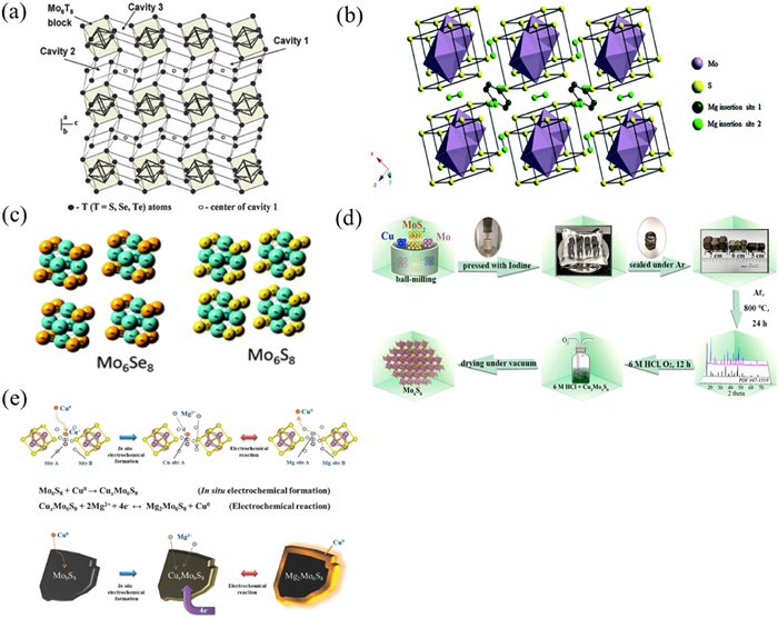
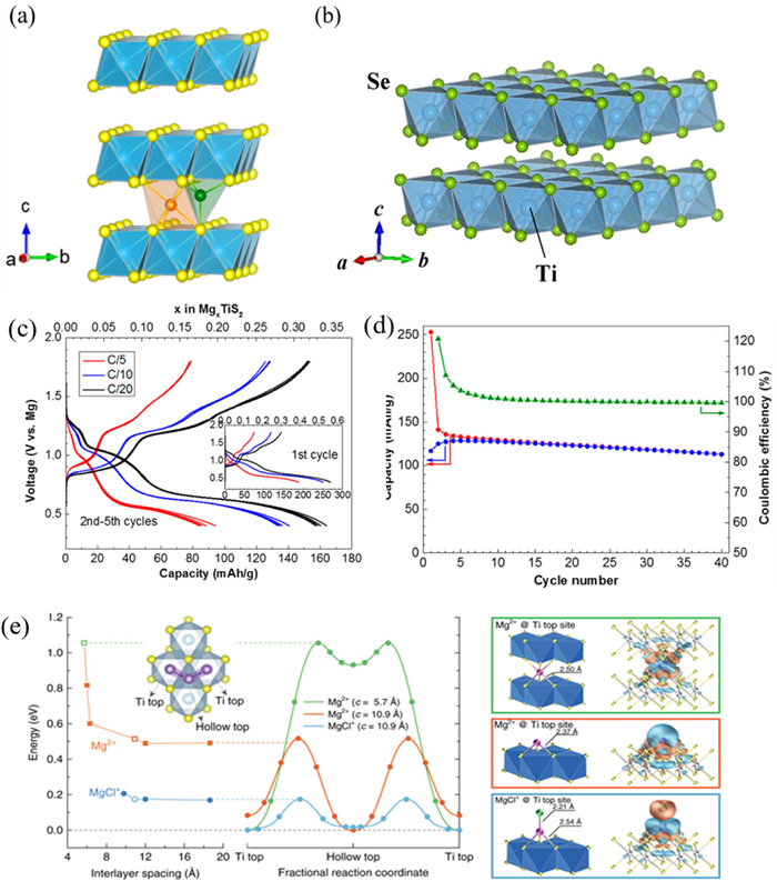
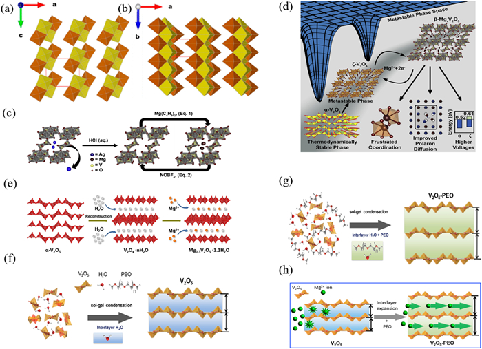
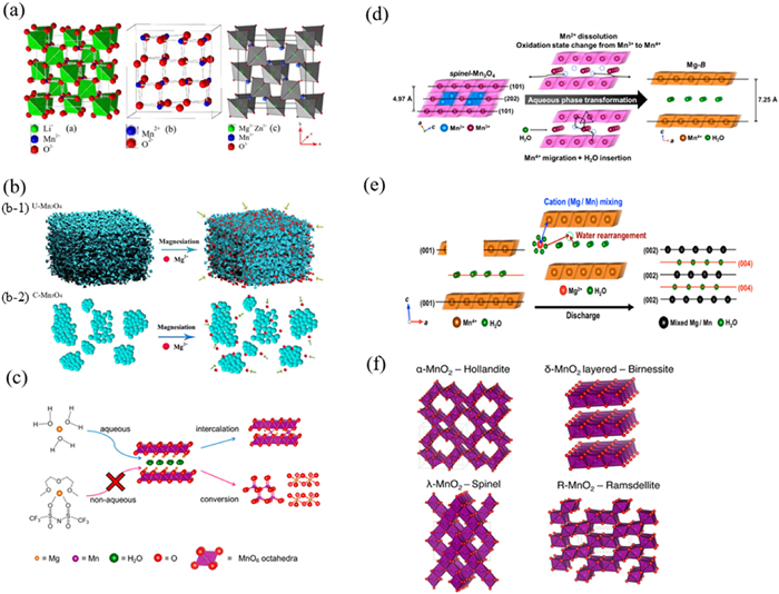
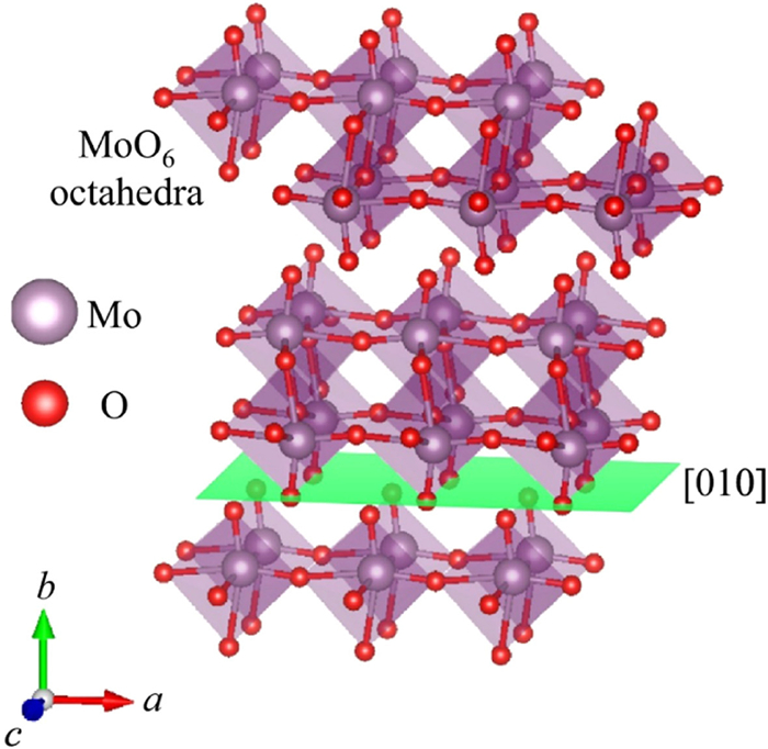
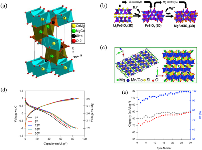
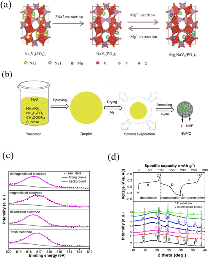
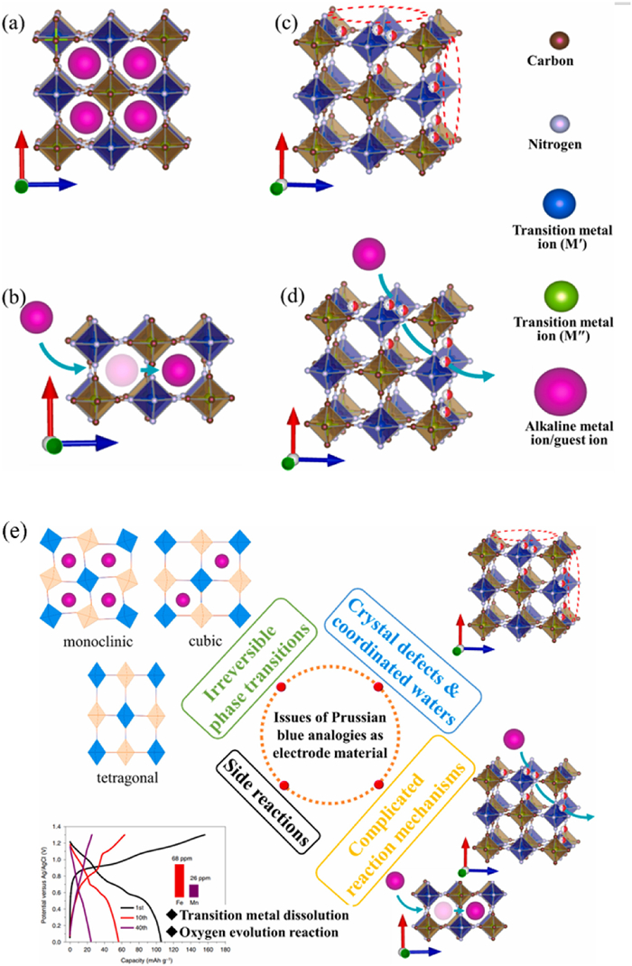
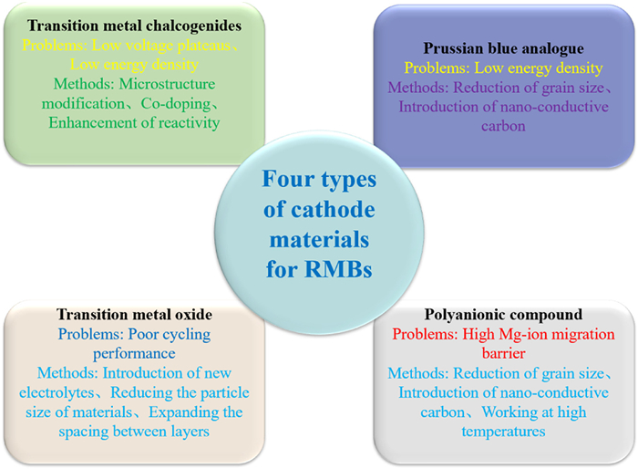

 下载:
下载:


 扫一扫看文章
计量
- PDF下载量: 3
- 文章访问数: 967
- HTML全文浏览量: 107
