Engineering Research Center for Energy Conversion and Storage Technology of Guizhou, School of Chemistry and Chemical Engineering, Guizhou University, Guiyang 550025, China
b.
Beijing Advanced Innovation Center for Soft Matter Science and Engineering & State Key Laboratory of Organic-Inorganic Composites, Beijing University of Chemical Technology, Beijing 100029, China
c.
Department of Applied Physics, The Hong Kong Polytechnic University, Hong Kong SAR 999077, China
Received Date:
03 January 2024 Accepted Date:
01 April 2024 Revised Date:
01 April 2024 Available Online:
15 November 2024
Abstract:
The device configuration with mesoporous titanium dioxide (m-TiO2) has garnered considerable attention as a promising solution for high-stable perovskite and dye-sensitized solar cells, although its application in organic solar cells remains unexplored. In this communication, we have incorporated this structure into both bulk-heterojunction (BHJ) and single-component organic solar cells (SCOSCs). Surprisingly, mesoporous OSCs (M-OSCs) demonstrate a deteriorative efficiency in BHJ-type cells, whereas this configuration succeeds in SCOSCs, exhibiting competitive performance with planar OSCs (P-OSCs). This pioneering study has resulted in a competitive power conversion efficiency of 9.67% for m-TiO2-based cells, marking a significant milestone in the advancement of OSCs. Importantly, profiting from the better ultraviolet resistance of m-TiO2 than zinc oxide, this M-OSC exhibits superior photostability than that of P-OSCs when subjected to continuous one-sun (AM1.5G) illumination. In its entirety, this research not only introduces the concept of M-OSCs for the first time but also unveils a novel device architecture poised to address the long-term stability concerns within the realm of OSCs.
In the past decade, significant advancements have been achieved in the power-conversion efficiencies (PCEs) of organic solar cells (OSCs), primarily attributed to the development of non-fullerene acceptors and polymer donor materials [1-6]. Nevertheless, the perceived issue of instability constitutes a substantial impediment to the widespread application of OSC technology. Stability stands as a critical determinant of the practicality, reliability, and commercial viability of OSCs. Its influence extends from cost-effectiveness and environmental considerations to seamless integration within existing energy infrastructure [7-10]. Consequently, intensifying research and development endeavors aimed at enhancing stability is imperative, with the objective of fostering broader adoption and augmenting the overall contribution of OSCs to the global energy landscape.
In pursuit of efficient and stable OSCs, several key strategies within device architecture have emerged. These encompass enhancing the chemical inertness of photoactive materials, stabilizing film morphology, implementing robust buffer layers, optimizing post-encapsulation processes, etc. [11-15]. These measures collectively culminate in the establishment of a stable interface, ensuring optimal contact with the photoactive layer while safeguarding against environmental stressors, including oxygen, moisture, and ultraviolet (UV) light exposure [16]. The inverted configuration, involving the deposition of the electron-transporting layer (ETL) in front of the photoactive layers, has garnered recognition as a promising solution for achieving high-stable OSCs [17,18]. Zinc oxide (ZnO), a typical n-type semiconductor with high electron mobility, has been widely employed as the ETL in inverted structured OSCs [19-21]. However, sol-gel processed ZnO films often exhibit elevated surface defect densities, such as surface groups, dangling bonds, and adsorbed oxygen molecules, which can serve as recombination centers for photogenerated carriers, potentially diminishing both efficiency and device stability [22-26]. For example, the “light-soaking” effect, observed when sol-gel ZnO or ZnO nanoparticles are utilized as ETLs in inverted OSCs, entails an enhancement in performance upon exposure to UV or white light. Various surface modification approaches have been explored to ameliorate these surface defects, including self-assembled monolayer modification, polymer surface modification, and composites of small molecules or polymers with ZnO films [27-29]. An alternative strategy is the application of mesoporous titanium dioxide (m-TiO2) in inverted devices [30,31], a technique well-established in stable perovskite and dye-sensitized solar cells in conventional devices [32-34]. Actually, m-TiO2 has been coupled with polymer donors in hybrid solar cells even before the emergence of perovskite cells [35,36]. While these hybrid solar cells exhibited low PCEs <2% due to excessive phase separation. Nevertheless, the extension of m-TiO2 into the field of OSCs remains an area largely unexplored.
In this context, we have investigated the integration of m-TiO2 into OSCs to chase high stability. Initially, various couples of BHJ-type OSCs expressed excellent PCEs in ZnO-based planar OSCs (P-OSCs, Fig. 1a). Unexpectedly, a huge efficiency decline, e.g., dropped from 16.20% to 8.68%, was observed in m-TiO2-based mesoporous OSCs (M-OSCs, Fig. 1b). Distinctively, single-component type solar cells (SCOSCs) [37] have demonstrated a transformative integration of m-TiO2, achieving performance metrics rivaling traditional P-OSCs with a remarkable PCE of 9.67%. Moreover, m-TiO2 has imparted superior photo- and thermal-stability to these M-OSCs under continuous one-sun (AM1.5G) illumination and heat at 80 ℃. This research not only introduces the concept of mesoporous OSCs, breaking new ground in the field but also introduces a novel device architecture poised to alleviate long-term stability concerns that have been pivotal in the further advancement of OSC technology.
Figure 1
Figure 1.
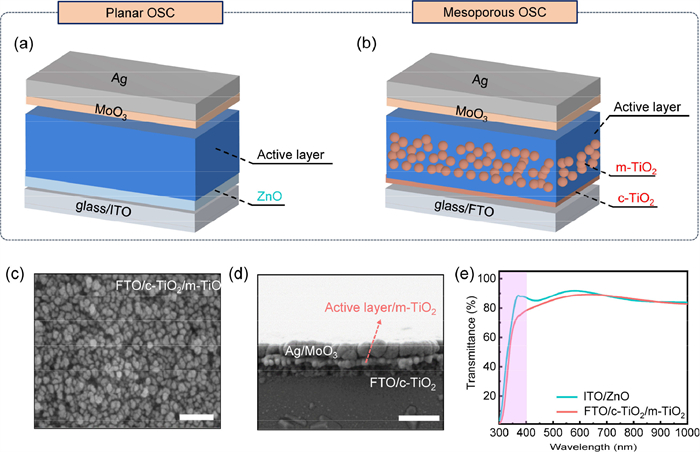
Schematic diagrams for (a) P-OSCs with a device structure of glass/ITO/ZnO/active layer/MoO3/Ag and (b) M-OSCs with a device structure of glass/FTO/c-TiO2/m-TiO2/active layer/MoO3/Ag. (c) The SEM image for m-TiO2 onto glass/FTO/c-TiO2 substrate. (d) Cross-section SEM view of the M-OSC device. Scale bar: 400 nm. (e) Transmittance spectra for glass/ITO/ZnO and glass/FTO/c-TiO2/m-TiO2 substrates.
P-OSCs adopt a typical inverted structure: glass/ITO/ZnO/active layers/MoO3/Ag (ITO: indium tin oxide; MoO3: molybdenum trioxide; Ag: silver; Fig. 1a). The M-OSCs combined the representative glass/FTO/c-TiO2/m-TiO2 (FTO: fluorine-doped tin oxide; c-TiO2: compact TiO2) device structure in perovskite solar cells and the MoO3/Ag back electrode in OSCs (Fig. 1b). The key procedure in the fabrication of mesoporous OSCs is the construction of c-TiO2 and m-TiO2 layers onto the glass/FTO substrate. Separately, the c-TiO2 layer was fabricated with a sol-gel method through the spin-coating of titanium isopropoxide/n‑butyl alcohol solution onto the etched FTO-coated glass, and then annealed at 150 ℃ for 15 min, and subsequently sintered at 500 ℃ for 30 min. The c-TiO2/m-TiO2 composite films were fabricated by coating the m-TiO2 slurry onto c-TiO2 films. Then, the films were annealed at 120 ℃ for 10 min and sintered at 500 ℃ for another 30 min. The scanning electron microscope (SEM) images of the c-TiO2/m-TiO2 composite film have been shown in Fig. 1c. Cross-sectional SEM views of M-OSCs have confirmed that the active layer is completely filled in the pores (Fig. 1d). In the transmittance spectra of Fig. 1e, we observed that the glass/FTO/c-TiO2/m-TiO2 composite layer exhibited better UV resistance, especially in the wavelength of 350–400 nm [38-41]. This UV block ability may increase the photostability of OSC devices, as the nonfullerene acceptors would photodegrade under continuous UV illumination [42-45].
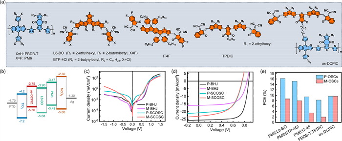
The double-cable conjugated polymer as-DCPIC [46,47] is selected for application in SCOSCs, while poly[[4,8-bis[5-(2-ethylhexyl)-4-fluoro-2-thienyl]benzo[1,2-b:4,5-b']dithiophene-2,6-diyl]-2,5-thiophenediyl[5,7-bis(2-ethylhexyl)-4,8-dioxo-4H,8H-benzo[1,2-c:4,5-c']dithiophene-1,3-diyl]-2,5-thiophenediyl] (PM6):L8-BO [48-51], PM6:BTP-4Cl [52], PM6:IT4F [53], and PBDB-T:TPDIC [54] have been selected as donors and acceptors for application in BHJ-type OSCs (Fig. 2a). Fig. 2b illustrates the energy levels cascade for each layer in the M-OSCs according to the previous report. It should be noted here that the conduction and valance bands of TiO2 are −4.2 eV and −7.2 eV [55,56], respectively, which is beneficial for electron extraction and hole block. Compared with their planar counterpart, M-OSCs exhibited lower leakage current densities when measuring the current-voltage (J-V) curves under dark circumstances (Fig. 2c). This characteristic would be beneficial to improve the reproductivity of OSC modules in flow-line production. We then attempted to compare the efficiencies of PM6:L8-BO based BHJ-type cells and as-DCPIC based SCOSCs between P- and M-OSCs. As shown in Fig. 2d and summarized in Table 1 and Tables S1-S4 (Supporting information), PM6:L8-BO based planar cells (denoted as P-BHJ) exhibited a high PCE of 16.20%, with an open-circuit voltage (VOC) of 0.87 V, a very high short-circuit current density (JSC) of 25.6 mA/cm2 and a fill factor (FF) of 0.72, respectively. However, in PM6:L8-BO based mesoporous cells (denoted as M-BHJ), the PCE has declined to 8.68% with degraded all the photovoltaic parameters: VOC, JSC, and FF value. Surprisingly, SCOSCs behaved better efficiency maintenance in the same device configuration transformation. as-DCPIC based planar devices (denoted as P-SCOSC) exhibited a high PCE of 9.68%, which only shifted to 9.67% in mesoporous cells (denoted as M-SCOSC). After comparing the influence of varying thicknesses of mesoporous TiO2 on device performance, as depicted in Fig. S1 (Supporting information), it was observed that the optimal mesoporous thickness for the device is approximately 150 nm.
Figure 2
Figure 2.
(a) Chemical formula of materials used in this work: PBDB-T, PM6, L8-BO, BTP-4Cl, IT4F, TPDIC, and as-DCPIC. (b) Energy levels diagrams for different layers in the mesoporous OSCs. (c) The dark current densities for mesoporous and planar type BHJ/SCOSCs. J-V characteristics for (d) as-DCPIC-based P-/M-SCOSCs and PM6:L8-BO-based P-/M-OSCs. (e) The comparison of PCEs for P-/M-OSCs with different photoactive layers.
Another observation was the distinct photoresponse in external quantum efficiency (EQE) spectra between BHJ-type OSCs and SCOSCs as shown in Fig. S2 (Supporting information). The M-BHJ exhibited lower photoresponse in the entire spectral range. However, for M-SCOSCs, in spite of a lower photoresponse observed in the short-wavelength range (300–600 nm), a higher photoresponse was observed in the long-wavelength range (600–850 nm). This distinction in EQE spectra were corresponded to the PCE difference between BHJ-type OSCs and SCOSCs. The m-TiO2 films are composed of nanoparticles in the range of 10–30 nm leading to a very large internal surface and porosities, which further cause different light refractive or scattering issues [57,58]. Therefore, the calculated current densities (Jcals) derived from the EQE curves (Table 1) were mismatched with the experimentally obtained JSC recorded during the J-V measurement. Furthermore, various BHJ couples have been employed to verify this phenomenon as shown in Fig. S3 (Supporting information) and summarized in Tables S5-S11 (Supporting information). As a matter of course, all the M-BHJ systems showed over 50% efficiency gaps compared with P-BHJ counterparts (Fig. 2e).
To further explore this huge transition gap between BHJ-type OSCs and SCOSCs from planar to mesoporous cells, we have conducted mobility characterization and charge dissociation/recombination kinetics. According to the space charge-limited current (SCLC) method [59,60], the electron mobilities (μe) were calculated to be were determined to be 3.66 × 10⁻⁵ and 2.08 × 10⁻³ cm2 V−1 s−1) for M-BHJ and M-SCOSCs (Fig. S4a and Table S12 in Supporting information), respectively. Notably, the μe of M-BHJ based on PM6:L8-BO was much lower than that of planar devices (8.40 × 10⁻³ cm2 V−1 s−1), while μe of M-SCOSC based on as-DCPIC was much higher than that of planar devices (3.57 × 10⁻⁵ cm2 V−1 s−1). The change in μe of mesoporous BHJ-type OSCs and SCOSCs were also responsible for the EQE response. Then, a photocurrent density (Jph) in relation to effective voltage (Veff) was scrutinized to assess the charge generation and extraction characteristics (Fig. S4b in Supporting information). The calculated efficiencies of exciton dissociation (denoted as P(E,T)) were 95.6% and 95.2% for M-BHJ and M-SCOSCs, respectively, suggesting a similar exciton dissociation process [61]. Furthermore, the investigation of charge recombination kinetics was performed through the examination of light-intensity-dependent VOC and JSC curves (Figs. S4c and d in Supporting information). Notably, the relationship between VOC and incident light intensity was established as null, where null represents the Boltzmann constant, T stands for the absolute temperature, q signifies the elementary charge, and Plight characterizes the incident light intensity. The simulated slopes in this characteristic were S = 1.82 and 1.65 kbT/q for M-BHJ and M-SCOSCs, respectively. These results point to the prevalence of monomolecular or trap-assisted charge recombination processes in these devices [62,63]. While in the relationship JSC ∝ Plightα (α ≤ 1) in Fig. S4d (Supporting information), the calculated α values for M-BHJ and M-SCOSCs were determined to be 0.914 and 0.962, respectively. These findings underscore the effective mitigation of both trap-assisted and bimolecular recombination processes in M-SCOSC than the M-BHJ, thereby contributing to larger JSC retention in this transformation. The main reason for the significant decrease in JSC in BHJ-type photoactive layer devices may be attributed to changes in the phase-separated structure (discussed later) and charge carrier dynamics (Fig. S5 in Supporting information), resulting in relatively lower charge dissociation and extraction efficiency within the mesoporous structure.
We then performed a comprehensive assessment of the long-term stability of these M-OSCs in the aspects of shelf stability, photo-, and thermal-stability, etc. At the beginning, the stability comparison of different OSCs was evaluated by a typical characteristic: T80 lifetime (80% of the initial PCE). For the shelf stability in Fig. S6 (Supporting information), the PCE retentions were 80% and 76% for P-BHJ and M-BHJ within 1258 h, corresponding to T80 lifetimes of 1258 and 586 h, respectively. While for SCOSCs, the planar devices showed a T80 of only 294 h. For comparison, M-SCOSC exhibited a much-improved T80 of 1929 h. Similar trends have also been observed in the photo-stability test as shown in Figs. 3a-d. The photostability test was conducted by placing OSCs in an N2-filled box under continuous light-emitting diode (LED) light illumination (Fig. S7 in Supporting information). After constant illumination for over 290 h, the PCE retentions were 74%, 50%, 77%, and 89% for planar/mesoporous BHJ-type OSCs and SCOSCs, respectively. The calculated T80 lifetimes for mesoporous SCOSC is 461 h, which is much higher than that of planar SCOSC (197 h). The unencapsulated OSC devices were placed on an 80 ℃ hot stage for thermal stability evaluation (Fig. S8 in Supporting information). Within constant heating at 80 ℃ for 1381 h, the PCE retentions were 70%, 48%, 82%, and 83% for planar/mesoporous BHJ-type OSCs and SCOSCs, respectively. These results are corresponding to T80 lifetimes of 46, 39, 2138, and 2914 h, respectively. The mesoporous structure could effectively improve the long-term stability of SCOSCs other than the BHJ-type OSCs, which may be due to different permeability of donor and acceptor materials. This permeability disparity arises from the distinct viscosities of polymer donors and small molecule acceptors in solution [64,65], potentially leading to the formation of larger phase-separated structures in the BHJ active layer solution during film formation, making it more prone to localized aggregation during prolonged operation.
Figure 3
Figure 3.
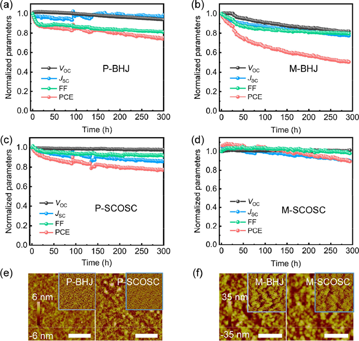
The photovoltaic parameters change of the encapsulated (a, b) BHJ-OSCs and (c, d) SCOSCs with mesoporous or planar structures based on PM6:L8-BO or as-DCPIC under continuous LED illumination (in an N2 filled glovebox). (e, f) The height AFM images for PM6:L8-BO and as-DCPIC layers in P- and M-OSCs. Scale bar: 1 µm. The inserts are the phase images.
Atomic force microscopy (AFM) images in Figs. 3e and f reveal the surface microstructural variations in different photovoltaic active layers within P- and M-OSCs, Nano-scale interpenetrating networks with fibrous film morphology can be observed in P-BHJ and P-SCOSCs, while a distinct film morphology alteration is noticeable upon transitioning from planar to mesoporous device structures. The measured root-mean-square (RMS) roughness based on PM6:L8-BO increases from 0.94 nm to 10.4 nm, and that based on as-DCPIC increases from 1.57 nm to 9.81 nm. This phenomenon can be attributed to the infiltration of the photoactive layer solution into the M-TiO2 layer during the film-forming process, consistent with SEM characterization results and likely a significant contributing factor to the performance degradation of M-BHJ. Similar morphology variations are also observed in both planar and mesoporous solar cells based on other BHJ photoactive layers, as illustrated in Fig. S9 (Supporting information). Similarly, two-dimensional grazing-incidence wide-angle X-ray scattering (GIWAXS) measurements were employed, as illustrated in Fig. S10 (Supporting information), to investigate the impact of the m-TiO2 layer on the molecular stacking order of these films. Specifically, in comparison to the previously reported diffraction peaks of blend films in planar device structures, the diffraction peaks of the PM6:L8-BO blends and as-DCPIC films in mesoporous device structures are significantly obscured by the diffraction characteristic peaks of m-TiO2.
In conclusion, our investigation into the integration of m-TiO2 into distinct OSC architectures has unveiled compelling insights. The unexpected decline in efficiency observed in BHJ-type Mesoporous OSCs highlights the intricate interplay of materials within this specific arrangement, shedding light on nuances that warrant further exploration. Conversely, the transformative integration of m-TiO2 in SCOSCs has yielded a remarkable PCE of 9.7%, rivaling that of conventional planar OSCs. This milestone not only underscores the potential of m-TiO2 within the realm of OSCs but also positions it as a significant contender in the ongoing pursuit of high-performance photovoltaics. Additionally, the superior photostability exhibited by Mesoporous OSCs, attributed to enhanced UV resistance compared to conventional ZnO, marks a crucial advancement in addressing long-term stability concerns. By introducing the concept of mesoporous OSCs and novel device architecture, this research paves the way for further progress in OSC technology, offering promising prospects for its broader application in the global energy landscape.
Declaration of competing interest
The authors declare that they have no known competing financial interests or personal relationships that could have appeared to influence the work reported in this paper.
This study is jointly supported by the Natural Science Special Foundation of Guizhou University (No. GZUTGH[2023]71), the Beijing Natural Science Foundation (No. JQ21006), and the National Natural Science Foundation of China (Nos. 92163128, 52073016). This work was further supported by the Fundamental Research Funds for the Central Universities (Nos. buctrc201828, XK1802–2), Open Project of State Key Laboratory of Organic-Inorganic Composites (No. oic-202201006), and Open Project of State Key Laboratory of Supramolecular Structure and Materials (No. sklssm2023010).
Supplementary materials
Supplementary material associated with this article can be found, in the online version, at doi:10.1016/j.cclet.2024.109849.
[1]
Y. Lin, J. Wang, Z.G. Zhang, et al., Adv. Mater. 27 (2015) 1170–1174. doi: 10.1002/adma.201404317
L.J.A. Koster, M. Kemerink, M.M. Wienk, K. Maturová, R.A.J. Janssen, Adv. Mater. 23 (2011) 1670–1674. doi: 10.1002/adma.201004311
[64]
B. Zhang, F. Yang, S.S. Chen, et al., Adv. Funct. Mater. 32 (2022) 2202011. doi: 10.1002/adfm.202202011
[65]
C.C. Xie, B.Q. Liu, C.Y. Xiao, et al., Chem. Eng. J. 461 (2023) 142124. doi: 10.1016/j.cej.2023.142124
Figure 1
Schematic diagrams for (a) P-OSCs with a device structure of glass/ITO/ZnO/active layer/MoO3/Ag and (b) M-OSCs with a device structure of glass/FTO/c-TiO2/m-TiO2/active layer/MoO3/Ag. (c) The SEM image for m-TiO2 onto glass/FTO/c-TiO2 substrate. (d) Cross-section SEM view of the M-OSC device. Scale bar: 400 nm. (e) Transmittance spectra for glass/ITO/ZnO and glass/FTO/c-TiO2/m-TiO2 substrates.
Figure 2
(a) Chemical formula of materials used in this work: PBDB-T, PM6, L8-BO, BTP-4Cl, IT4F, TPDIC, and as-DCPIC. (b) Energy levels diagrams for different layers in the mesoporous OSCs. (c) The dark current densities for mesoporous and planar type BHJ/SCOSCs. J-V characteristics for (d) as-DCPIC-based P-/M-SCOSCs and PM6:L8-BO-based P-/M-OSCs. (e) The comparison of PCEs for P-/M-OSCs with different photoactive layers.
Figure 3
The photovoltaic parameters change of the encapsulated (a, b) BHJ-OSCs and (c, d) SCOSCs with mesoporous or planar structures based on PM6:L8-BO or as-DCPIC under continuous LED illumination (in an N2 filled glovebox). (e, f) The height AFM images for PM6:L8-BO and as-DCPIC layers in P- and M-OSCs. Scale bar: 1 µm. The inserts are the phase images.

 DownLoad:


 下载:
下载:


