Citation:
Zhijie Zhang, Xun Li, Huiling Tang, Junhao Wu, Chunxia Yao, Kui Li. Cs2CuBr4 perovskite quantum dots confined in mesoporous CuO framework as a p-n type S-scheme heterojunction for efficient CO2 photoconversion[J]. Chinese Chemical Letters,
2024, 35(11): 109700.
doi:
10.1016/j.cclet.2024.109700
Cs2CuBr4 perovskite quantum dots confined in mesoporous CuO framework as a p-n type S-scheme heterojunction for efficient CO2 photoconversion
English
Cs2CuBr4 perovskite quantum dots confined in mesoporous CuO framework as a p-n type S-scheme heterojunction for efficient CO2 photoconversion
Received Date:
09 November 2023 Accepted Date:
03 January 2024 Revised Date:
30 November 2023 Available Online:
15 November 2024
Abstract:
Heterojunction engineering is recognized as a promising strategy to modulate the photocatalytic properties of semiconductors. Herein, lead-free Cs2CuBr4 perovskite quantum dots (PQDs) were confined in a mesoporous CuO framework and a p-n type S-scheme heterojunction of Cs2CuBr4/CuO (CCB/CuO) photocatalyst was fabricated. Experimental characterizations confirmed the effective confinement of the Cs2CuBr4 PQDs in the mesoporous CuO framework, which enabled intimate contact in the interface of CCB/CuO heterojunction, thus facilitating the interfacial charge migration and separation between p-type CuO and n-type Cs2CuBr4. Owing to the outstanding charge transport property and CO2 adsorption capacity, the developed CCB/CuO heterojunction exhibited remarkably enhanced photocatalytic CO2 conversion efficiency with an electron consumption rate (Relectron) of 281.1 µmol g−1 h−1, which was approximately 2.8 times higher than that of pristine Cs2CuBr4. These findings provide some insights into the rational engineering design of lead-free perovskite-based heterostructures for efficient photocatalytic CO2 conversion.
With the massive consumption of fossil fuels and significant emissions of greenhouse gases, the world is faced with more and more serious energy shortage and climate issues. Especially, the emission of carbon dioxide has brought about great concern, as the CO2 greenhouse effect has caused the notorious global warming. Therefore, the capture, storage, and conversion of CO2, are of great significance to resolve the energy crisis and environmental issues [1–3]. By imitating the natural photosynthesis, photocatalytic CO2 reduction to high-density hydrocarbon fuels using the inexhaustible solar energy is a green and sustainable approach [4,5]. Up to date, a variety of semiconductors have been explored as photocatalysts, including TiO2 [6], metal-organic frameworks [7–10], single-atom catalysts [11,12], etc. The continuous exploration of low-cost, stable, and efficient photocatalysts for CO2 reduction is one of the strategic alternatives for the practical application of such a promising technology.
As a newly emerging class of optoelectronic materials, halide perovskite quantum dots (PQDs) have attracted significant attention due to their unique advantages of high extinction coefficients, suitable energy band structure, and long carrier diffusion length [13,14]. Traditional lead-based PQDs, especially CsPbBr3, have been extensively studied as photocatalysts for CO2 conversion due to their excellent light harvesting ability and appropriate band positions [15–17]. However, the high Pb toxicity has impeded the practical applications of the lead-containing perovskites. In order to conquer this, researchers have diverted their attention to exploiting lead-free perovskites for photocatalysis. Among which, the Cu-based perovskite Cs2CuBr4 has been demonstrated as a promising candidate owing to its suitable bandgap and nontoxicity [18]. Nevertheless, the intrinsic large surface energy of PQDs makes them easy to agglomerate, which can affect their long-term stability. Moreover, the rapid recombination of photogenerated charge carriers in pristine PQDs is unfavourable for their photocatalytic activity. These problems can be overcome by confining the Cs2CuBr4 PQDs in a mesoporous semiconductor framework to construct a heterojunction.
Among various heterojunctions, the newly-emerging S-scheme heterojunction has received significant attention for its unique superiorities [19]. There are four types of S-scheme heterojunction: n-n junction, p-p junction, p-n junction, and n-p junction, where the left letter represents oxidation photocatalyst (OP) and the right one represents reduction photocatalyst (RP). Taken the p-n junction as an example, OP is a p-type semiconductor while RP is an n-type semiconductor. In any case, the precondition for the formation of an S-scheme heterojunction is that the conduction band (CB) position and Fermi level (EF) of OP should be simultaneously lower than those of RP. Generally, the EF gap between the n-type and p-type semiconductors is larger than that between n-type and n-type semiconductors. In other words, the p-n heterojunction has an intensified internal electric field (IEF) compared with the n-n heterojunction, which can provide a more powerful driving force for charge transfer. However, most of the reported S-scheme heterojunctions are n-n type, and the p-n type S-scheme heterojunction is rarely reported.
Copper oxide (CuO) is a p-type semiconductor with a monoclinic structure and narrow band gap (Eg = 1.2–2.0 eV) [20], which has been widely applied in catalysis, batteries, gas sensing, and photoelectrochemical cells [21,22]. Motivated by its good stability, availability, high absorption in visible light spectrum, and p-type semiconducting property, we intend to construct a p-n type S-scheme heterojunction by confining the Cs2CuBr4 PQDs in a mesoporous CuO framework, which is expected to bring about multiple advantages: Firstly, the confinement of Cs2CuBr4 in mesoporous CuO can effectively prevent the PQDs from aggregation; Secondly, the unique mesoporous structure of CuO can afford the photocatalyst with high specific surface area and numerous active sites, thus favoring the adsorption/activation of CO2 molecules; Thirdly, the construction of S-scheme heterojunction between CuO and Cs2CuBr4 can simultaneously promote the charge separation and maximize the reduction/oxidation abilities of the CCB/CuO photocatalyst, which can lead to improved photocatalytic performance. Considering all the above merits, the CCB/CuO p-n heterojunction is expected to be a promising photocatalyst for CO2 conversion.
The CCB/CuO p-n type S-scheme photocatalyst was fabricated by a facile impregnation approach (Fig. S1 in Supporting information). The crystal structures of the synthesized CuO, Cs2CuBr4, and CCB/CuO heterojunctions were investigated by XRD analysis. As shown in Fig. S2a (Supporting information), for pure CuO and Cs2CuBr4, all the diffractions peaks match well with the standard card of CuO (JCPDS card No. 9016105) and Cs2CuBr4 (JCPDS card No. 71–1462), implying that CuO and Cs2CuBr4 with high purity and crystallinity are obtained. For the XRD patterns of CCB/CuO heterojunctions, characteristic diffraction peaks of both CuO and Cs2CuBr4 could be observed, and the diffraction peaks of Cs2CuBr4 increase with its loading amount. Moreover, in the small-angle XRD patterns of CuO and the CCB/CuO heterojunctions (Fig. S2b in Supporting information), a distinct diffraction peak at ca. 0.7° could be detected, which is characteristic of mesoporous materials [23]. The above results imply the successful synthesis of mesoporous CuO and the retainment of the mesoporous structure during the combined process.
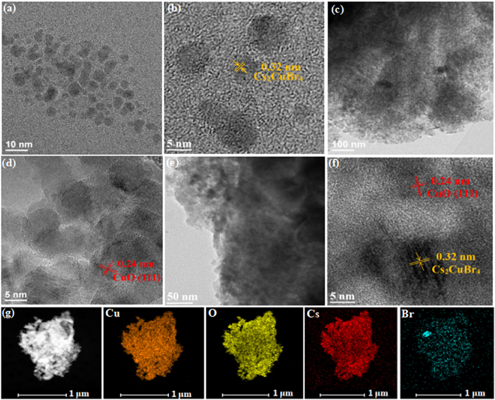
The mesoporous structure is supposed to provide the CuO framework with a high BET surface area. As shown in Fig. S3a (Supporting information), the N2 adsorption-desorption isotherms of CuO and the CCB/CuO heterojunctions display a typical IV isotherm with a type H3 hysteresis loop, which is characteristic of mesoporous structured materials [24]. CuO has a high specific surface area of ca. 58.78 m2/g, and encapsulation of Cs2CuBr4 PQDs into the mesopores leads to decreased BET surface areas (Table S1 in Supporting information). This is because the presence of Cs2CuBr4 PQDs in the mesopores of CuO framework hinder N2 adsorption during the BET measurement. This assumption is further confirmed by the pore size distribution curves. As shown in Fig. S3b and Table S1 (Supporting information), the pore sizes of CCB/CuO are smaller than that of CuO, and decrease gradually with the increased content of Cs2CuBr4 PQDs. This observation further indicates the successful loading of Cs2CuBr4 PQDs in the mesopores of the CuO framework.In order to examine the microstructure of the prepared Cs2CuBr4, CuO, and the loading state of Cs2CuBr4 PQDs on CuO, TEM and HRTEM images were performed. As shown in Fig. 1a, Cs2CuBr4 exhibits nanospherical structure with the sizes of 2–5 nm. The HRTEM image (Fig. 1b) displays a distinct interplanar spacing of 0.32 nm, which corresponds to the (203) plane of Cs2CuBr4. The TEM image of CuO is shown in Fig. 1c and Fig. S4 (Supporting information), which possesses abundant pores in the structure, indicating that mesoporous CuO has been successfully fabricated by duplicating the structure of the MCM-48 template. In the HRTEM image of CuO (Fig. 1d), the lattice spacing of 0.24 nm could be clearly observed, which is consistent with the (111) plane of CuO. The TEM image of the CCB/CuO heterojunction is shown in Fig. 1e, which indicates that the basic structure of the CuO framework is retained, with some small nanoparticles decorated in the pores. In the HRTEM image of the CCB/CuO heterojunction (Fig. 1f), the crystal lattices of Cs2CuBr4 and CuO could be observed, where the lattice spacing of 0.32 nm and 0.24 nm are in good agreement with the (203) and (111) planes of Cs2CuBr4 and CuO, respectively. The corresponding EDX spectra also certifies the presence of all the elements of Cs, Cu, Br, and O in the heterojunction catalyst (Fig. S5 in Supporting information). In addition, the elemental mapping of the CCB/CuO heterojunction (Fig. 1g) indicates that Cs2CuBr4 PQDs are evenly dispersed in the pores of CuO. All the above characterizations confirm the successful loading and homogeneous distribution of Cs2CuBr4 PQDs in the mesopores of the CuO framework.
Figure 1
Figure 1.
(a) TEM and (b) HRTEM images of Cs2CuBr4 PQDs. (c) TEM and (d) HRTEM images of mesoporous CuO framework. (e) TEM and (f) HRTEM images of the CCB/CuO heterojunction. (g) EDX element mapping analysis of the CCB/CuO heterojunction.
The UV–vis DRS spectra (Fig. S6a in Supporting information) shows that both CuO and Cs2CuBr4 exhibit remarkable photoabsorption properties, with the absorption edge extended to the whole visible and partial infrared region. The CCB/CuO heterojunctions show intermediate photoabsorption properties between pristine CuO and Cs2CuBr4. The broad photoabsorption range illustrates small band gaps of CuO and Cs2CuBr4, which are determined to be 1.57 and 1.52 eV, respectively (Fig. S6b in Supporting information). The conducting type of Cs2CuBr4 and CuO is clarified by the Mott-Schottky (M-S) plots. As shown in Fig. S7a and b (Supporting information), the slope of the M-S plot of Cs2CuBr4 is positive, while that of CuO is negative, which indicates the n and p-type semiconductor characteristics of Cs2CuBr4 and CuO, respectively. Fig. S8 (Supporting information) presents the valence band XPS (VB-XPS) spectra of Cs2CuBr4 and CuO, which indicates valence band potentials (EVB) of 0.86 and 1.83 eV for Cs2CuBr4 and CuO, respectively. Correspondingly, their conduction band potentials (ECB) are calculated to be −0.66 and 0.26 eV by the formula of ECB = EVB - Eg. Based on the obtained values, the band energy positions of Cs2CuBr4 and CuO are drawn schematically. As shown in Fig. S9 (Supporting information), both the ECB and EVB of Cs2CuBr4 are higher than that of CuO. In other words, Cs2CuBr4 and CuO have staggered energy level alignments, which is an important prerequisite for the formation of S-scheme heterojunction.
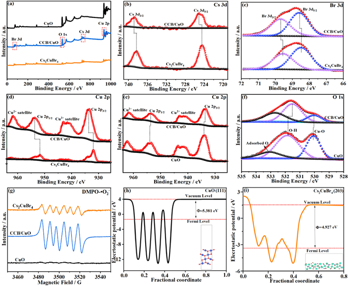
The chemical state of elements in CCB/CuO heterojunction and the interaction between Cs2CuBr4 and CuO were studied by XPS. The full scan XPS spectra (Fig. 2a) shows that the CCB/CuO sample exhibits all the expected elements of Cs, Cu, Br, and O. The high resolution XPS spectra of Cs 3d in pristine Cs2CuBr4 and CCB/CuO heterojunction are compared in Fig. 2b. The Cs 3d spectra for pristine Cs2CuBr4 exhibits two binding energy peaks at 738.3 and 724.5 eV, corresponding to Cs 3d3/2 and Cs 3d5/2, respectively. After formation of heterojunction with CuO, these two peaks display a positive shift by 0.5 eV to 738.8 and 725.0 eV, respectively. Similarly, the Br 3d and Cu 2p spectra also exhibit positive shift (Figs. 2c and d). Conversely, the peaks of Cu 2p spectra for the CCB/CuO heterojunction exhibits a negative shift compared with that of pristine CuO (Fig. 2e). Similar to that of Cu 2p spectra, the peak of the lattice oxygen in CCB/CuO also shifts negatively to lower values in relative to that of CuO (Fig. 2f). The above phenomena indicate that the electrons cloud density of Cs2CuBr4 decreases upon the formation of heterojunction, while the electrons cloud density of CuO increases [25]. In other words, the electrons transfer from the CB of Cs2CuBr4 to the CB of CuO in the CCB/CuO heterojunction. Such a directional electron transfer could create an internal electric field (IEF) at the interface pointing from Cs2CuBr4 to CuO, facilitating the formation of S-scheme heterojunction between CuO and Cs2CuBr4.
Figure 2
Figure 2.
XPS spectra of CuO, Cs2CuBr4, and CCB/CuO heterojunction: (a) Full survey, (b) Cs 3d, (c) Br 3d, (d) Cu 2p, (e) Cu 2p, and (f) O 1s spectra in CuO, Cs2CuBr4, and CCB/CuO heterojunction. (g) ESR spectra of CuO, Cs2CuBr4, and CCB/CuO heterojunction; Calculated work functions of (h) CuO and (i) Cs2CuBr4.
ESR spectra is further performed to gain more convincing evidence of the charge transfer direction in the CCB/CuO heterojunction. As shown in Fig. 2g, characteristic DMPO-·O2− signals are detected for the pristine Cs2CuBr4 and CCB/CuO heterojunction, while hardly perceptible DMPO-·O2− signal is detected for pristine CuO, since its conduction band potential is more positive than that of O2/·O2− (−0.33 V vs. NHE) [26]. In addition, the DMPO-·O2− signal for the CCB/CuO heterojunction is much stronger than that of Cs2CuBr4, implying effective electron accumulation in the CCB/CuO heterojunction. This phenomenon provides additional evidence to verify that the photoexcited electrons in the CB of CuO transfer to the VB of Cs2CuBr4 via the S-scheme electron transfer route in the CCB/CuO heterojunction, rather than the type II mode [27]. Work function (null) is a critical parameter to investigate the electron delivery direction within semiconductor heterojunctions. As shown in Figs. 2h and i, the work function of CuO (111) and Cs2CuBr4 (203) are 5.381 and 4.927 eV, respectively, indicating that CuO has a lower Fermi level than Cs2CuBr4 PQDs, which meet the requirement for establishing S-scheme heterojunction.
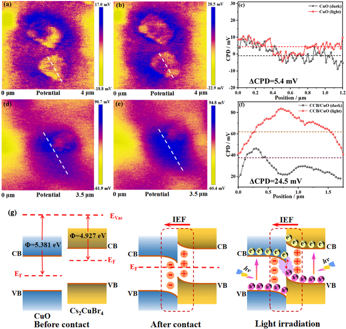
Photo-irradiated KPFM was performed to confirm the enhanced charge transfer driven by the IEF. Figs. 3a-c present the KPFM images and the corresponding surface potential profiles of CuO under dark and light conditions, which indicate a trivial change of the surface potential (5.4 mV) before and after light irradiation. Such a slight variation implies the rapid charge carrier recombination of pristine CuO. In contrast, the surface potential of CCB/CuO undergoes a remarkable increasement of 24.5 mV under light irradiation, as a result of the photogenerated electrons depletion on the surface (Figs. 3d-f) [28]. Such a significant difference in the surface photovoltage between CuO and CCB/CuO verifies that the photogenerated electrons of CuO transfer to Cs2CuBr4 PQDs confined in pores under light illumination.
Figure 3
Figure 3.
Surface potential distribution changes of (a-c) CuO and (d-f) CCB/CuO heterojunction under dark and light conditions (ΔCPD = CPDlight - CPDdark). (g) Scheme illustrating the charge transfer mechanism of the CCB/CuO p-n heterojunction.
Based on the above analysis, the S-scheme charge transfer mode of CCB/CuO is illustrated in Fig. 3g. When the p-type CuO and n-type Cs2CuBr4 are delicately contacted, a p-n heterojunction of CCB/CuO would be formed, in which electrons spontaneously slide across the interface from n-type Cs2CuBr4 to p-type CuO until their Fermi levels are aligned. Consequently, an electron depletion layer will be formed at the Cs2CuBr4 side, where Cs2CuBr4 is positively charged. On the contrary, an electron accumulation layer will be formed at CuO side, where CuO is negatively charged. The establishment of the space charge region leads to the formation of a strong IEF directing from Cs2CuBr4 to CuO. When the CCB/CuO heterojunction is irradiated, the IEF would lead the photo-excited electrons on the CB of CuO to recombine with the photo-excited holes on the VB of Cs2CuBr4. As such, the interfacial charge separation and transfer are facilitated, and simultaneously retaining the strongly reducing electrons at the Cs2CuBr4 side for CO2 reduction.
Photocatalytic reduction of CO2 was conducted under visible light irradiation to assess the photocatalytic performances of the synthesized samples. The yields of reduction products after reaction for 4 h over different catalysts are illustrated in Fig. 4a. For Cs2CuBr4 and the CCB/CuO heterojunctions, CO and CH4 are detected as the main reduction products. No gaseous product is generated by pristine CuO, which could be due to its insufficient reduction potential considering its positive ECB. However, when the CuO framework is loaded with Cs2CuBr4 PQDs, the developed CCB/CuO heterojunctions exhibit significantly enhanced photocatalytic performances for CO2 reduction. Especially, the products yield for the 0.5CCB/CuO sample is found to be the highest, with the production rates of 60.88 µmol g−1 h−1 for CO and 19.91 µmol g−1 h−1 for CH4. These values correspond to an electron consumption rate (Relectron = 2R(CO) + 8R(CH4)) high up to 281.1 µmol g−1 h−1, which is 2.8 times higher than that of pristine Cs2CuBr4 PQDs (Fig. 4b). Additionally, the CO2 photoreduction performance of CCB/CuO is higher than other similar PQDs-based photocatalytic systems (Table S2 in Supporting information), which highlights the merits of the current system.
Figure 4
Figure 4.
Photocatalytic CO2 reduction tests: (a) Yields of CO and CH4 from photocatalytic reaction over CuO, Cs2CuBr4, and CCB/CuO heterojunctions with different loading amounts of Cs2CuBr4; (b) Comparison of Relectron for photocatalytic CO2 reduction over CuO, Cs2CuBr4, and CCB/CuO heterojunctions; (c) Photocatalytic CO2 reduction tests under different conditions; (d) GC–MS spectra of the photocatalytic product over CCB/CuO using 13CO2 as carbon source; (e) Recycling tests of the CCB/CuO heterojunction; (f) Long-term photocatalytic tests of CCB/CuO; (g) In-situ DRIFTS of CO2 photoreduction over CCB/CuO with increasing irradiation time; (h) Proposed reaction pathway of CO2 photoreduction over CCB/CuO; (i) Schematic illustration of the mechanism of photocatalytic CO2 reduction over the CCB/CuO heterojunction.
In addition, blank tests were performed to examine the origin of the gaseous products, as shown in Fig. 4c. The blank experiments without light irradiation or the photocatalyst show negligible production of gases, implying that the reaction is carried out by photocatalysis. Blank experiments were also conducted in Ar system. The insignificant production of gaseous products may be originated from the photoreduction of adsorbed CO2 on the catalyst surface, indicating that the carbonaceous products in the photocatalytic reaction come from CO2. The carbon source of produced CO and CH4 was further traced by using a 13C isotopic label. As shown in Fig. 4d, the peaks with the m/z values of 17 and 29 are assigned to the photogenerated 17CH4 and 13CO, respectively, indicating that the gaseous products are indeed originated from the reduction of CO2.
In order to assess the stability and reusability of the 0.5CCB/CuO sample, cyclic experiments were performed under the same conditions. The photocatalyst exhibits no significant reduction of photocatalytic efficiency after five cycles (Fig. 4e), indicating its excellent reusability. Moreover, long-term test shows that the 0.5CCB/CuO heterojunction displays good long-time stability, with almost linear production of CH4 and CO for over 28 h (Fig. 4f). Especially, no significant change of phase structure or morphology is found in the XRD pattern (Fig. S10 in Supporting information) and TEM image (Fig. S11 in Supporting information) of 0.5CCB/CuO before and after reaction, demonstrating excellent stability of the photocatalyst.
The visible-light-induced transient photocurrent density provides a useful indication of the charge separation efficiency of a semiconductor photocatalyst. Fig. S12a (Supporting information) displays the transient photocurrent densities of Cs2CuBr4, CuO, and CCB/CuO catalysts over several light on-off cycle modes. Obviously, the photocurrent densities of CCB/CuO heterojunctions are significantly enhanced compared with pristine Cs2CuBr4 and CuO, indicating that the construction of CCB/CuO heterojunction could effectively promote the separation of photogenerated electrons and holes. Moreover, electrochemical impedance spectroscopy (EIS, Fig. S12b in Supporting information) results show that the CCB/CuO heterojunctions possess smaller semicircle in contrast with the pristine counterparts, which manifests accelerated interface charge transfer of the heterojunction photocatalyst. The superiority could be attributable to the creation of IEF by the formation of S-scheme heterojunction between Cs2CuBr4 and CuO, which is beneficial for the charge separation.
The mesoporous CuO framework can not only facilitate the charge separation in Cs2CuBr4, but also promote the CO2 absorption. As is well known, the abundant pores in a mesoporous material could afford a large surface area and strong adsorption of reactant molecules, which is significant for the subsequent catalytic reaction [29,30]. Hence, the CO2 uptake capacity of the samples was investigated by CO2 adsorption/desorption curves. As shown in Fig. S13 (Supporting information), pristine Cs2CuBr4 exhibits poor CO2 adsorption capacity at 273 K, while the CCB/CuO heterojunction shows an CO2 adsorption capacity 2.35 times higher than that of Cs2CuBr4. Moreover, the temperature-programmed desorption of CO2 (CO2-TPD) was performed, which is regarded as an effective technique to probe the interaction between the catalyst and adsorbed CO2 molecules [31,32]. As shown in Fig. S14 (Supporting information), the CCB/CuO heterojunction displays higher CO2 desorption temperature than pristine Cs2CuBr4, accompanied with a larger peak area under the desorption curve, indicating improved CO2 adsorption capacity and stronger interaction with CO2 molecules of the CCB/CuO catalyst.
To further track the evolution of reaction intermediates over the CCB/CuO catalyst during CO2 photoreduction, in-situ DRIFTS is monitored. As shown in Fig. 4g, no signals can be detected in the dark condition (0 min), however, several distinct signal peaks begin to appear under light condition with increasing irradiation time. The appearance of these signals imply the formation of reaction intermediates, mainly including •CO2− radical at 1213 and 1260 cm−1, hydrocarboxylate (HCO3−) at 1391 and 1447 cm−1, bidentate carbonate species (b-CO32−) at 1318 and 1600 cm−1, and monodentate carbonates (m-CO32−) at 1516 cm−1 [33,34]. Especially, a crucial intermediate for CO generation, COOH*, is detected at 1558 and 1650 cm−1. Based on the in situ DRIFTS analysis, the CO2 photoreduction pathway is proposed as the following steps (Fig. 4h): First, CO2 molecules are adsorbed on the surface of CCB/CuO and activated to form CO2*, which is the main reaction intermediate. On the other hand, some of CO2 molecules react with H2O to form H2CO3, which can be easily further decomposed into protons (H+) and HCO3−/CO32−. Then, the produced H+ and electrons react with CO2* to form the key intermediate of COOH*, which is further converted to CO* or CH3O* by H+ and e−. Finally, CO* is desorbed from the catalyst surface to generate CO, while CH3O* is hydrogenated to CH4 with the photogenerated electrons.
Based on the above analysis, the mechanism for the enhanced CO2 photoreduction performance of CCB/CuO is extrapolated and depicted in Fig. 4i. When the CCB/CuO photocatalyst is irradiated by visible light, both Cs2CuBr4 PQDs and CuO could absorb light and produce photo-generated electrons at their CB and photo-generated holes at their VB. Due to the lower EF position of CuO than that of Cs2CuBr4, the photoexcited electrons of Cs2CuBr4 move directly to the CB of CuO. Such electron transfer results in an IEF at the interface of the p-n heterojunction directing from Cs2CuBr4 to CuO. Driven by the IEF, the photoexcited electrons on the CB of CuO would recombine with the photo-excited holes on the VB of Cs2CuBr4. As such, the photo-excited electrons are accumulated at the CB of Cs2CuBr4 while the photo-excited holes are accumulated at the VB of CuO. Therefore, spatial charge separation of CCB/CuO heterojunction is achieved, while maintaining the high reduction potential at the Cs2CuBr4 side for efficient CO2 photoreduction. Besides, as evidenced by the CO2 adsorption/desorption curves and CO2-TPD, the use of mesoporous CuO as the framework to confine Cs2CuBr4 PQDs can promote the adsorption of CO2 molecules, which is beneficial to the subsequent photoreduction reaction. Benefiting from all the above advantages, the developed CCB/CuO heterojunction exhibits significantly enhanced photocatalytic performance for CO2 reduction.
In summary, lead-free Cs2CuBr4 PQDs were encapsulated in a mesoporous CuO framework, obtaining an efficient p-n type S-scheme heterojunction of CCB/CuO for photocatalytic CO2 reduction. The S-scheme charge transfer mechanism of the CCB/CuO heterojunction was confirmed collectively by various characterization techniques and theoretical calculations. The potential of the developed CCB/CuO heterojunction in photocatalytic CO2 reduction was evaluated under visible light. Interestingly, a remarkable electron consumption rate (Relectron) of 281.1 µmol g−1 h−1 was achieved by the CCB/CuO heterojunction, which was 2.8 times higher than that of pristine Cs2CuBr4. The improved photocatalytic activity of the CCB/CuO heterojunction could be attributed to the enhanced charge separation efficiency and promoted CO2 adsorption capability. Our present research may open new avenues for the development of more effective PQDs-based photocatalytic systems for solar-to-fuel conversions.
Declaration of competing interest
The authors declare that they have no known competing financial interests or personal relationships that could have appeared to influence the work reported in this paper.
Acknowledgments
This work was financially supported by Natural Science Foundation of Shanghai (No. 22ZR1460700) and Shanghai Institute of Technology (No. XTCX2022–28).
Supplementary materials
Supplementary material associated with this article can be found, in the online version, at doi:10.1016/j.cclet.2024.109700.
[1]
M. Lu, M. Zhang, J. Liu, et al., J. Am. Chem. Soc. 144 (2022) 1861–1871. doi: 10.1021/jacs.1c11987
Figure 1
(a) TEM and (b) HRTEM images of Cs2CuBr4 PQDs. (c) TEM and (d) HRTEM images of mesoporous CuO framework. (e) TEM and (f) HRTEM images of the CCB/CuO heterojunction. (g) EDX element mapping analysis of the CCB/CuO heterojunction.
Figure 2
XPS spectra of CuO, Cs2CuBr4, and CCB/CuO heterojunction: (a) Full survey, (b) Cs 3d, (c) Br 3d, (d) Cu 2p, (e) Cu 2p, and (f) O 1s spectra in CuO, Cs2CuBr4, and CCB/CuO heterojunction. (g) ESR spectra of CuO, Cs2CuBr4, and CCB/CuO heterojunction; Calculated work functions of (h) CuO and (i) Cs2CuBr4.
Figure 3
Surface potential distribution changes of (a-c) CuO and (d-f) CCB/CuO heterojunction under dark and light conditions (ΔCPD = CPDlight - CPDdark). (g) Scheme illustrating the charge transfer mechanism of the CCB/CuO p-n heterojunction.
Figure 4
Photocatalytic CO2 reduction tests: (a) Yields of CO and CH4 from photocatalytic reaction over CuO, Cs2CuBr4, and CCB/CuO heterojunctions with different loading amounts of Cs2CuBr4; (b) Comparison of Relectron for photocatalytic CO2 reduction over CuO, Cs2CuBr4, and CCB/CuO heterojunctions; (c) Photocatalytic CO2 reduction tests under different conditions; (d) GC–MS spectra of the photocatalytic product over CCB/CuO using 13CO2 as carbon source; (e) Recycling tests of the CCB/CuO heterojunction; (f) Long-term photocatalytic tests of CCB/CuO; (g) In-situ DRIFTS of CO2 photoreduction over CCB/CuO with increasing irradiation time; (h) Proposed reaction pathway of CO2 photoreduction over CCB/CuO; (i) Schematic illustration of the mechanism of photocatalytic CO2 reduction over the CCB/CuO heterojunction.

 DownLoad:


 下载:
下载:


