Table 1.
Detailed reaction conditions for different samples.
Citation:
Juanjuan Wang, Fang Wang, Bin Qin, Yue Wu, Huan Yang, Xiaolong Li, Lanfang Wang, Xiufang Qin, Xiaohong Xu. Controlled synthesis and excellent magnetism of ferrimagnetic NiFe2Se4 nanostructures[J]. Chinese Chemical Letters,
2024, 35(11): 109449.
doi:
10.1016/j.cclet.2023.109449

Controlled synthesis and excellent magnetism of ferrimagnetic NiFe2Se4 nanostructures
English
Controlled synthesis and excellent magnetism of ferrimagnetic NiFe2Se4 nanostructures
Abstract:
3d transition metal chalcogenides have attracted much attention due to their unique magnetic properties. Although various Cr, V, and Fe-based chalcogenides have been fabricated recently, the limited Curie temperature (TC) still hinders their practical application. Based on the structural and magnetic advantages of MFe2O4 and Fe3Se4, we developed a one-pot solution synthesis method for the fabrication of NiFe2Se4 nanostructures with structural continuity, to facilitate the investigation of their magnetic properties. Notably, the morphology of NiFe2Se4 can be controlled from nano-rods to nano-platelets by controlling the growth direction. The coercivity (HC) of NiFe2Se4 with nano-cactus structure exhibits a maximum of 12.77 kOe at 5 K. The coercivity of ferrimagnetic NiFe2Se4 nano-platelets can be further adjusted to 1.52 kOe at room temperature. These results show that the magnetic properties of NiFe2Se4 can be significantly modified by controlling their morphologies. We also extend the method to the synthesis of CoFe2Se4 nano-cactus with an ultrahigh coercivity of 17.85 kOe at 5 K. Obviously, the synthesis strategy and their excellent magnetic properties of MFe2Se4 have sparked interest in ternary transition metal selenides as potential hard magnetic materials.
-
Key words:
- Transition metal selenides
- / Hard magnetic materials
- / NiFe2Se4
- / Ferrimagnetic
- / Solution-process
-
Transition metal oxides/chalcogenides are regarded as one of the most promising candidates for next-generation magnetic nanomaterials because of the strong spin-orbit coupling [1–3]. These novel materials open the door to exploring new applications such as magnetic sensing and information storage [4–6]. For the development of practical applications, the Curie temperature (TC) of nano-magnets must be above room temperature. Fe-based magnetic nanomaterials inspired significant research attention because of their higher TC than room temperature [7–9], such as Fe-based oxides and selenides [10–12]. Two well-known magnetic compounds Fe3O4 and Fe3Se4 have monoclinic phases with an approximate composition. Both of them are ferrimagnetic, and their hysteresis curve indicates that the magnetic properties of Fe3Se4 (coercivity reaching 40 kOe at 10 K and 4 kOe at room temperature) are significantly better than that of Fe3O4 (coercivity is 274 Oe at 10 K, and negligible at room temperature) [13,14]. Another important class of complex oxides MFe2O4 (M: transition metal) with the cubic spinel structure, where some Fe atoms in Fe3O4 are substituted by the transition metal atoms, exhibit a decrease in structural symmetry due to the introduction of dissimilar metal atoms. As a result, they typically demonstrate high magnetic ordered temperature and large net magnetization [15,16]. Due to the versatility of M (M = Fe, Mn, Co, Ni), MFe2O4 has been chosen as the most frequent nanomagnetic system and has shown great potential applications, such as information storage, electronic devices, and medical diagnostics [17–20]. Similarly, when the heavier Se atom replaces the O atom, another interesting spinel compound MFe2Se4 is given [21,22]. In theory, the stoichiometric MFe2Se4 are ferrimagnetic and associated with the low symmetry NiAs-type crystal lattice. In the unit cell of MFe2Se4, the metal atoms occupy the octahedral holes within a hexagonally close-packed Se lattice, and there are alternating stacks of metal-deficient and metal-full layers along the c-direction [23]. The metal vacancy exhibits weak internal bonding in the {101} plane system, which plays a vital role in determining the structure and magnetic properties. While the practical applications in catalysis, ceramics, and energy storage have been extensively reported [24–26], specific discussions on the magnetic properties are notably absent. Therefore, the densely packed solid state form of nanostructures MFe2Se4 materials, which exhibit strong spin-orbit interaction, hold promise as potential candidates for high-performance electromagnetic and spintronic devices in the future.
Driven by the unique structural properties of MFe2Se4 and their promising applications in magnetic devices, it is very necessary to explore their new physical properties. However, the ternary transition metal chalcogenides (TMCs) suffer from poor synthesizing, and it is always accompanied by the existence of some binary impurities, which limits their further exploration. In order to explore the various ternary transition metal chalcogenides, it is highly desirable to find a simple and general synthesis method. The liquid phase synthesis method has been widely used to obtain TMCs with tunable morphologies and properties [27–33]. Therefore, we put forward a high-temperature organic-solution phase method for preparing MFe2Se4 nanostructures.
Here, we synthesized ternary NiFe2Se4 and CoFe2Se4 using a simple one-pot solution-phase method. High-quality NiFe2Se4 nanostructures with tunable morphologies and magnetic properties were obtained by heating a precursor mixture in a coordinating organic solvent. The shapes of NiFe2Se4 nanostructures can be regulated from nano-rods, nano-cactus to nano-platelets. The growth direction has shifted from longitudinal growth along the 〈010〉 direction, with nano-rods averaging 110 nm in length, to the formation of nano-platelets with a uniform size of 40 nm. These nanostructures exhibit hard magnetic properties, and the magnetic properties of NiFe2Se4 can be further tuned to room temperature for the nano-platelets with an average size of 40 nm. CoFe2Se4 nano-cactus with ultrahigh coercivity (HC) of 17.85 kOe at 5 K was also synthesized by this method. Our approach offers a novel system for exploring the hard magnetic properties of more binary-transition metals chalcogenides.
All chemicals and solvents were of analytical grade purity and were used for synthesis without any further purification. Iron(III) 2,4-pentanedionate [Fe(acac)3, 97%] and selenium powder [Se, 200 mesh, 99.5%] were purchased from Alfa Aesar. Nickel acetylacetonate [Ni(acac)2, 96%] and cobalt(II) acetylacetonate [Co(acac)2, 98%] were supplied by J&K Scientific. Oleylamine (OLA, 80%–90%) and Oleic acid (OA, >85%) were obtained from Aladdin and TCI, respectively. The Hexane (98%) and ethanol (99.7%) were purchased from Tianjin Fengchuan Chemical Reagent Co., Ltd., and Tianjin Beichen District Fangzheng Reagent Factory, respectively.
A series of MFe2Se4 (M: Ni, Co) nanostructures were synthesized by a simple one-pot high-temperature organic-solution phase method. During this typical synthesis, first, stoichiometric metal source and Se were mixed in solvent OLA and ligand OA in the 100 mL round-bottomed four-necked flask equipped with a thermometer. Then, the unit was heated to 120 ℃ slowly and kept for 30 min to remove dissolved oxygen and low boiling solvent under the inert gas flow. Finally, at a ramping rate of 2 ℃/min, the solution temperature was raised to a specific temperature, and the reaction mixture was maintained for 60 min at this temperature for the reaction. After that, the solution was naturally cooled to room temperature by removing the heating source. The NiFe2Se4 and CoFe2Se4 nanostructures were repeatedly precipitated and washed by adding 20 mL of hexane and 10 mL of ethanol alternately and recentrifuging at 8000 rpm for 6 min. The samples of NiFe2Se4 with different reaction conditions were labeled as Sample A, Sample B, and Sample C, respectively. The specific synthesis morphology and corresponding reaction conditions are shown in Table 1.
Table 1
The phase structures were identified using powder X-ray diffraction (XRD), and the measurements were performed on a Bruker D8 Advance diffractometer with a Cu Kα radiation source (λ = 0.154 nm). The morphologies and high-resolution TEM (HRTEM) images were analyzed using a transmission electron microscope (TEM). Comprehensive morphologies and elemental mapping of the samples were achieved through SEM, equipped with an energy-dispersive X-ray spectroscope (EDS). The magnetic measurements, including the magnetic hysteresis loops (M-H) and temperature-dependent magnetization curves (M-T), were measured using a physical property measurement system (PPMS, QD Dyna Cool) with a field of up to 50 kOe. The elemental compositions and chemical valence states were characterized by an X-ray photoelectron spectrometer (XPS, Thermo ESCALAB 250XI).
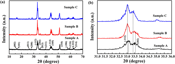
XRD analysis was carried out to characterize the crystal structure of ternary NiFe2Se4 nanomaterials. As shown in Fig. 1a, the diffraction peaks of the NiFe2Se4 nanostructures are in agreement with the standard NiFe2Se4 phase (JCPDS card No. 01–089–1968), which has a monoclinic structure with a space group of I2/m(12) and lattice parameters of a = 6.15 Å, b = 3.54 Å, and c = 10.92 Å. These main peaks located at 33.24°, 33.62°, 44.01°, 44.47°, and 51.49° can accurately correspond to
null , (202),null , (105), and (310), respectively. Moreover, no impurity peaks were observed in the figure. This indicates that the NiFe2Se4 prepared by this simple one-step method proposed is a pure phase and highly crystalline. The enlarged XRD pattern of the NiFe2Se4 structure shows a slight shift for the peaks ofnull and (202) planes (Fig. 1b), which is attributed to the variations in lattice constants resulting from different reaction conditions during sample production. These variations are related to the relative positions of different metals and metal vacancies within the MFe2Se4 lattice, which can be influenced by the actual synthesis process. The displacement of the (202) plane is particularly noticeable, which can be attributed to the weak binding of the {101} plane family. Moreover, the lattice distortion cannot induce phase transition. Therefore, it seems that within our experimental conditions, the lattice structure cannot be significantly altered. Sample C obtained by the reaction at 360 ℃ has a relatively lower diffraction angle θ, while Sample A has a relatively higher diffraction angle θ. According to the Bragg formula, indicating that Sample C has the largest interplanar spacing d, corresponding Sample A has the smallest d value. The high quality NiFe2Se4 pure phase can be obtained by a one-pot organic high-temperature liquid-phase method. The difference in these structures is related to the reaction conditions involved in the nucleation and growth processes during the synthesis.Figure 1
 Figure 1. (a) XRD patterns of samples with different synthesis conditions. (b) The magnified NiFe2Se4 nanostructures (112) and (202) peak.
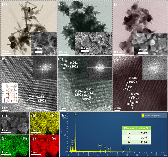
To further analyze the microstructure and morphologies of samples synthesized under different conditions, TEM, SEM, HRTEM, and fast Fourier transforms (FFT) analysis were performed. The TEM and SEM study of the NiFe2Se4 nanostructures under different conditions shows the variety of microstructure for all the samples (Fig. 2). Using Fe(acac)3 as the Fe source, Ni(acac)2 as the Ni source, OLA as the solvent, and the mixture reacts at 320 ℃, we can obtain nano-rods (Sample A) structures with an average length of about 110 nm (Fig. 2a). The HRTEM image of the nano-rods show that the lattice fringes with d-spacing of 0.263 nm correspond to the (202) plane of NiFe2Se4 (Fig. 2b). This result indicates that the facet of {101} is the exposed face of the nano-rods, and the nano-rods tend to grow along the 〈010〉 axis, which is consistent with the structural characteristics of NiFe2Se4. The inset FFT pattern of the single-crystalline nano-rods further demonstrates the great crystallinity along the long b-axis.
Figure 2
 Figure 2. Typical TEM and HRTEM images of NiFe2Se4 nanostructures, the inset is the corresponding SEM and FFT result. (a, b) nano-rods, (c, d) nano-cactus with rod-like features growing on the surface, (e, f) nano-platelets. (g-k) The SEM elemental mapping and EDS of Fe, Ni, and Se for nano-platelets.
While maintaining the remaining conditions, by adding a strong coordination surfactant OA, an interesting nano-cactus (Sample B) morphology can be obtained. The nano-cactus structure exhibits a large number of spikes growing on the upper surface, facing completely outwards, similar to cacti (Fig. 2c). The HRTEM analysis revealed lattice fringes with a d-spacing of 0.263 nm for the (202) plane, indicating the formation of smaller nano-rod structures due to the favorable growth along the b-axis (Fig. 2d). During the reaction process, OA promotes the growth of nanostructures, but the limited diffusion speed of Fe atoms results in incomplete coordination in the {010} plane. As a result, these nano-rods tend to aggregate into a three-dimensional nano-cactus structure to reduce their surface energy. The FFT of the inner inset in Fig. 2d further confirms the pure phase of the NiFe2Se4 nanostructures monoclinic system. Furthermore, as the reaction temperature increased to 360 ℃ during the process, the independent nano-platelets (Sample C) with sizes of approximately 40 nm were formed (Fig. 2e). The HRTEM image (Fig. 2f) shows the d-spacing of 0.270 nm and 0.548 nm, corresponding to the
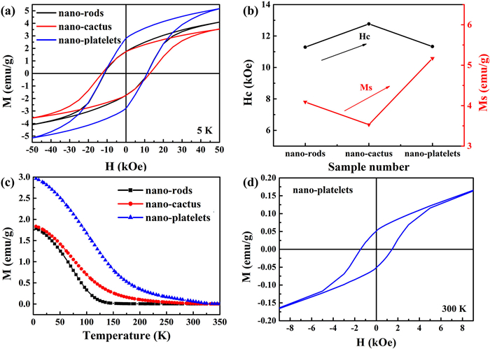
null and (002) planes of NiFe2Se4, respectively. This is because OA promoted growth along the lateral direction. Simultaneously, the adsorption of OA suppresses the growth of nanostructures along the b-axis. As the temperature increases, Fe fully diffuses and the Fe atoms on the {101} planes become fully coordinated, resulting in a decrease in the surface energy of the nanostructure. This decrease in surface energy prevents the aggregation of the nanostructures into 3D structures and is beneficial to the formation of independent 2D nano-platelets. As a result, the final morphology of the nanostructures is determined by precise control of the initial nucleation stage, as well as by surfactants, reaction time, and temperature during later growth stages. The composition analysis reveals a uniform distribution of Fe, Ni, and Se elements within a single hexagonal nanosheet (Figs. 2g–j). To confirm the compositions of the sample nano-platelets, we used EDS spectra to determine the average compositions of Fe, Ni, and Se, which were found to be 28.69 at%, 14.46 at%, and 56.86 at%, respectively (Fig. 2k). This suggests an elemental composition ratio of Ni:Fe:Se close to 1:2:4. The synthesis process has a unique feature in that different coordinating ligands, such as OA, can be used to control growth rates in the lateral or vertical direction, and different reaction precursors can be used to control nucleation rates, resulting in a variety of morphologies.The magnetic properties of NiFe2Se4 nanostructures were investigated by PPMS, and the M-H curves are displayed in Fig. 3a. All of the NiFe2Se4 nanostructures exhibit hard magnetic properties at the low temperature of 5 K. For nano-rods, the M-H shows hard magnetic behavior with an HC of 11.29 kOe, and an MS of 4.09 emu/g at an external field of 50 kOe. According to KU ≈ HC·MS (KU is the magnetocrystalline anisotropy constant), the KU of nano-rods is estimated to be 4.6 × 10⁵ erg/cm3. The large magnetocrystalline anisotropy originates from the monoclinic structure of NiFe2Se4 with lower lattice symmetry. In contrast, nano-cactus and nano-platelets show higher HC values of 12.77 kOe, and 11.33 kOe, corresponding to MS of 3.53 emu/g and 5.17 emu/g at 5 K, respectively (Figs. 3a and b). The magnetic differences in samples are a result of variations in d-spacing and cell volume. The d-spacing increases for different samples, leading to a significant decrease in interplanar antiferromagnetic interactions and magnetic enhancement [7].
Figure 3
 Figure 3. The magnetic properties of samples. (a) The M-H curve under the 5 K. (b) The corresponding HC and MS values of the various samples at 5 K. (c) The M-T curve and (d) the M-H curve of nano-platelets, under the 300 K.
To further study the magnetic properties of different samples at different temperatures, an M-T curve was carried out. Fig. 3c shows that the TC values of NiFe2Se4 nanostructures vary among different samples. The TC of these samples exhibits a significant enhancement. In particular, the hard magnetic properties of nano-platelets with larger d-spacing can be extended to room temperature 300 K. We identify the underlying mechanism of ferrimagnetism in our systems, namely the dominant in-plane ferromagnetic exchange interactions against the inter-plane antiferromagnetic exchange interactions. With increasing d-spacing from nano-rods to nano-platelets, the interplanar antiferromagnetic exchange (the interaction between antiferromagnetic spins on adjacent planes) decreases significantly (approximately proportional to 1/d5), while the in-plane ferromagnetic exchange interaction remains relatively constant [34]. This difference in exchange interactions enhances the energy difference between antiferromagnetic and ferromagnetic states (AFM-FM). According to the Heisenberg model, the exchange interaction parameter leads to a ferromagnetic enhancement, resulting in an increasing in TC [35]. Fig. 3d illustrates the magnetic properties of nano-platelets at 300 K, the M-H exhibits hard magnetic behavior with an HC of 1.52 kOe. This example demonstrates that the magnetic properties of NiFe2Se4 can be significantly modified by controlling the structures of the material, which is closely related to the interaction between magnetic ions of the corresponding nanostructures.
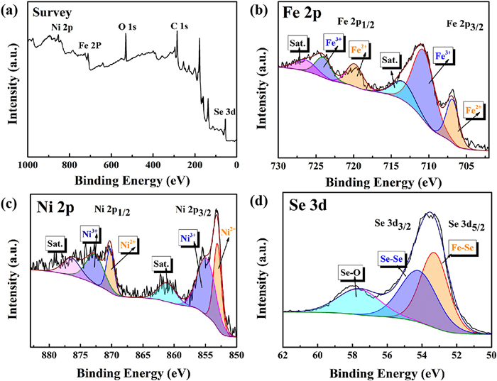
XPS was utilized to analyze the elemental composition and chemical states of the NiFe2Se4 nano-platelets. The low-resolution XPS survey confirms the presence of Fe, Ni, Se, O, and C signals in the NiFe2Se4 (Fig. 4a). The O peaks observed can be attributed to the adsorption of air on the sample surfaces. The high-resolution Fe 2p spectra of the NiFe2Se4 nanostructure show the presence of spin-orbit doublet characteristics (Fig. 4b). The characteristic peaks with binding energies at 707.02 eV (2p3/2) and 719.82 eV (2p1/2) can be attributed to Fe2+, whereas the peaks at 711.03 eV (2p3/2) and 724.28 eV (2p1/2) correspond to the higher oxidation state, Fe3+. The Ni 2p fine spectrum displays the peaks corresponding to the 2p3/2 and 2p1/2 orbitals (Fig. 4c), which can be best fitted the two spin-orbit doublets of Ni2+ (2p3/2 ≈ 853.08 and 2p1/2 ≈ 870.23 eV), Ni3+ (2p3/2 ≈ 854.85 and 2p1/2 ≈ 872.69 eV) as well as two shake-up satellites. Interestingly, the Se 3d high-resolution spectra shown in Fig. 4d are best fitted with two prominent peaks of Se 3d5/2 and Se 3d3/2 located around 53.28 and 54.18 eV, respectively. Additionally, a peak of Se-O is observed at 57.62 eV. This result satisfies the valence balance of NiFe2Se4 system and is consistent with previous studies [36,25].
Figure 4
 Figure 4. (a) XPS survey spectra of NiFe2Se4 sample (nano-platelets). High-resolution spectra of (b) Fe 2p, (c) Ni 2p, (d) Se 3d.
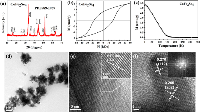
Building upon the previously discussed synthetic concepts, we further synthesized the CoFe2Se4 ternary nanostructure. Fig. 5a illustrates the crystal structure of the sample, with all peaks aligning well with the CoFe2Se4 phase (JCPDS No. 89–1967). TEM analysis reveals that CoFe2Se4 exhibits a nano-cacti structure with uniform dispersion and an average size of approximately 100 nm (Fig. 5d). The HRTEM images (Figs. 5e and f) display d-spacing values of 0.270 nm and 0.265 nm, which correspond to the
null and (202) planes of CoFe2Se4, respectively. These results confirm that CoFe2Se4 pure-phase nanostructures have been successfully synthesized. Magnetic analysis reveals that CoFe2Se4 exhibits a high coercivity (HC) of 17.85 kOe at 5 K, a value comparable to that of CoFe2O4 nanoparticles (20 kOe at 10 K) [19]. Notably, its coercivity significantly surpasses that of the recently popular material Cr2Te3, which only reaches a maximum Hc of 9.6 kOe at the same low temperature of 5 K [37]. Therefore, CoFe2Se4 is a promising candidate for a hard magnetic material at low temperature (Fig. 5b). Fig. 5c reveals a significant difference in TC at 150 K compared to NiFe2Se4 with the same morphology, which can be attributed to the distinct local magnetic moments of Ni and Co.Figure 5
 Figure 5. (a) XRD patterns, (b) M-H curve under the 5 K, (c) M-T curve, (d-f) TEM and HRTEM of CoFe2Se4.
In summary, NiFe2Se4 nanostructures exhibiting abundant morphology were synthesized through a facile one-pot high-temperature organic-solution-phase method. The magnetic properties of NiFe2Se4 nanostructures can be easily tuned by altering their morphologies due to their difference in d-spacing. The synthesized NiFe2Se4 nano-platelets demonstrate an impressive HC value, reaching up to 11.33 kOe at 5 K and 1.52 kOe at room temperature. Another significant compound CoFe2Se4 nanostructures with ultrahigh coercivity (HC = 17.85 kOe at 5 K) have also been synthesized by a similar method. Our research could potentially advance the study of ternary transition metal selenides hard magnetic materials.
Declaration of competing interests
The authors declare that they have no known competing financial interests or personal relationships that could have appeared to influence the work reported in this paper.
Acknowledgments
This work is supported by the National Natural Science Foundation of China (Nos. 51971122, 52371191, 52301244), and the National Key R&D Program of China (No. 2022YFB3505301).
-
-
[1]
M. Samad, N. Sarikhan, M. Zirak, et al., Nanoscale Horiz. 3 (2018) 90–204. doi: 10.1039/C7NH00137A
-
[2]
C. Chen, X.D. Chen, C.W. Wu, et al., Adv. Mater. 34 (2022) 2107512. doi: 10.1002/adma.202107512
-
[3]
C. Gong, L. Li, Z.L. Li, et al., Nature 546 (2017) 265–269. doi: 10.1038/nature22060
-
[4]
H. Zeng, S. Sun, Adv. Funct. Mater. 18 (2008) 391–400. doi: 10.1002/adfm.200701211
-
[5]
B. Balasubramanian, B. Das, R. Skomski, et al., Adv. Mater. 25 (2013) 6090–6093. doi: 10.1002/adma.201302704
-
[6]
M. Yue, X.Y. Zhang, J.P. Liu, et al., Nanoscale 9 (2017) 3674–3697. doi: 10.1039/C6NR09464C
-
[7]
Z. Zhao, J. Zhou, L.H. Liu, et al., Nano Lett. 22 (2022) 1242–1250. doi: 10.1021/acs.nanolett.1c04403
-
[8]
Y.Z. Wang, P. Wang, H. Wang, et al., Adv. Mater. 35 (2023) 2209465. doi: 10.1002/adma.202209465
-
[9]
H. Zeng, J. Li, Z.L. Wang, et al., Nano Lett. 4 (2004) 187–190. doi: 10.1021/nl035004r
-
[10]
E. Tombácz, R. Turcu, V. Socoliuc, et al., Biochem. Bioph. Res. Co. 468 (2015) 442–453. doi: 10.1016/j.bbrc.2015.08.030
-
[11]
J.J. Wang, F. Wang, D.Y. Guo, et al., J. Alloy. Compd. 938 (2023) 168694. doi: 10.1016/j.jallcom.2022.168694
-
[12]
Z. Chen, C. Wu, Z. Zhang, et al., Chin. Chem. Lett. 29 (2018) 1601–1608. doi: 10.1016/j.cclet.2018.08.007
-
[13]
H.W. Zhang, G. Long, D. Li, et al., Chem. Mater. 23 (2011) 3769–3774. doi: 10.1021/cm201610k
-
[14]
T. Ozkaya, M.S. Toprak, A. Baykal, et al., J. Alloy. Compd. 472 (2009) 18–23. doi: 10.1016/j.jallcom.2008.04.101
-
[15]
R.Q. Cheng, L. Yin, Y. Wen, et al., Nat. Commun. 13 (2022) 5241. doi: 10.1038/s41467-022-33017-1
-
[16]
C.D. Pham, J. Chang, M.A. Zurbuchen, et al., ACS Appl. Mater. Interfaces 9 (2017) 36980–36988. doi: 10.1021/acsami.7b08097
-
[17]
R. Nepal, Z. Wang, S. Dai, et al., ACS Appl. Mater. Interfaces 12 (2020) 38788–38795. doi: 10.1021/acsami.0c10790
-
[18]
D. Erdem, N.S. Bingham, F.J. Heiligtag, et al., Adv. Funct. Mater. 26 (2016) 1954–1963. doi: 10.1002/adfm.201504538
-
[19]
S.H. Sun, H. Zeng, D.B. Robinson, et al., J. Am. Chem. Soc. 126 (2004) 273–279. doi: 10.1021/ja0380852
-
[20]
H. Wei, T. Peng, B. Wang, et al., Colloid. Surface. A 649 (2022) 129510. doi: 10.1016/j.colsurfa.2022.129510
-
[21]
Z. Ali, M. Asif, X. Huang, et al., Adv. Mater. 30 (2018) 1802745. doi: 10.1002/adma.201802745
-
[22]
S. Si, C. Li, X. Wang, et al., Cryst. Growth Des. 5 (2005) 391–393. doi: 10.1021/cg0497905
-
[23]
A. Hayashi, K. Imada, K. Inoue, et al., B. Ins. Chem. Res. Kyoto Univ. 64 (1986) 186–206.
-
[24]
Y. Wang, S. Guo, K. Chen, et al., Electrochim. Acta 353 (2020) 136563. doi: 10.1016/j.electacta.2020.136563
-
[25]
S. Ibraheem, S. Chen, L. Peng, et al., Appl. Catal. B: Environ. 265 (2020) 118569. doi: 10.1016/j.apcatb.2019.118569
-
[26]
W. Deng, J. Chen, L. Yang, et al., Small 17 (2021) 2101058. doi: 10.1002/smll.202101058
-
[27]
C. Tan, H. Zhang, Nat. Commun. 6 (2015) 7873. doi: 10.1038/ncomms8873
-
[28]
H. Yang, F. Wang, H.S. Zhang, et al., J. Am. Chem. Soc. 142 (2020) 4438–4444. doi: 10.1021/jacs.9b13492
-
[29]
J.L. Fenton, R.E. Schaak, Angew. Chem. 129 (2017) 6564–6567. doi: 10.1002/ange.201701087
-
[30]
T. Ge, L. Shen, J. Li, et al., Colloid. Surface. A 635 (2022) 128069. doi: 10.1016/j.colsurfa.2021.128069
-
[31]
F. Wang, H. Yang, H.S. Zhang, et al., Nano Lett. 21 (2021) 7684–7690. doi: 10.1021/acs.nanolett.1c02481
-
[32]
H.X. Huang, J.J. Zha, S.S. Li, et al., Chin. Chem. Lett. 33 (2022) 163–176. doi: 10.1016/j.cclet.2021.06.004
-
[33]
C.F. Wang, W. Zhang, W.W. Li, et al., Chin. Chem. Lett. 30 (2019) 1390–1392. doi: 10.1016/j.cclet.2019.03.007
-
[34]
X. Li, J. Yang, J. Mater. Chem. C 2 (2014) 7071–7076. doi: 10.1039/C4TC01193G
-
[35]
C.G. Duan, R.F. Sabiryanov, W.N. Mei, et al., Appl. Phys. Lett. 88 (2006) 182505. doi: 10.1063/1.2200767
-
[36]
Z. Ali, M. Asif, T. Zhang, et al., Small 15 (2019) 1901995. doi: 10.1002/smll.201901995
-
[37]
F. Wang, J. Du, R.F. Sun, et al., Nanoscale 10 (2018) 11028–11033. doi: 10.1039/C8NR02272K
-
[1]
-
Figure 1 (a) XRD patterns of samples with different synthesis conditions. (b) The magnified NiFe2Se4 nanostructures (112) and (202) peak.
Figure 2 Typical TEM and HRTEM images of NiFe2Se4 nanostructures, the inset is the corresponding SEM and FFT result. (a, b) nano-rods, (c, d) nano-cactus with rod-like features growing on the surface, (e, f) nano-platelets. (g-k) The SEM elemental mapping and EDS of Fe, Ni, and Se for nano-platelets.
Figure 3 The magnetic properties of samples. (a) The M-H curve under the 5 K. (b) The corresponding HC and MS values of the various samples at 5 K. (c) The M-T curve and (d) the M-H curve of nano-platelets, under the 300 K.
Figure 4 (a) XPS survey spectra of NiFe2Se4 sample (nano-platelets). High-resolution spectra of (b) Fe 2p, (c) Ni 2p, (d) Se 3d.
Figure 5 (a) XRD patterns, (b) M-H curve under the 5 K, (c) M-T curve, (d-f) TEM and HRTEM of CoFe2Se4.
-

 DownLoad:


 下载:
下载:


 扫一扫看文章
计量
- PDF下载量: 3
- 文章访问数: 1067
- HTML全文浏览量: 84
