Figure 1.
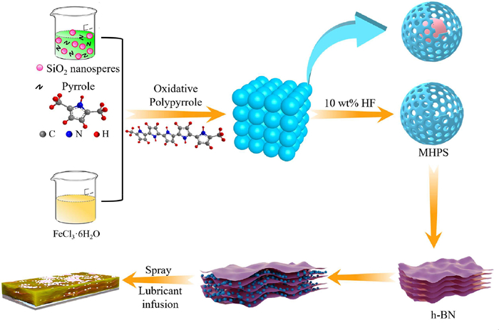
Schematic diagram of SLIPS coating preparation.
Hexagonal boron nitride based slippery liquid infused porous surface with anti-corrosion, anti-contaminant and anti-icing properties for protecting magnesium alloy
Wenhao Yan , Shuaiya Xue , Xuerui Zhao , Wei Zhang , Jian Li

Lightweight development has become imperative in the present era of energy saving, emission reduction and green development [1–3]. Mg alloy as a light metal structural alloy with a density of only 1.8 g/cm3, and has excellent specific strength, ductility, thermal conductivity, and machinability [4,5]. Thus, Mg alloys have outstanding competitiveness in aerospace, marine, automotive, and other fields with stringent weight limitations [6]. Unfortunately, Mg alloy is severely susceptible to corrosion in atmospheric, soil, and marine environments due to the high chemical activity [7]. The occurrence of corrosion can not only cause irreversible damage to the appearance and mechanical properties of Mg alloy, but can also cause huge economic losses and safety hazards in industrial production. In order to solve this problem, the fabrication of protective coatings on Mg alloy is one of the proven methods. Protective coatings prevent the corrosion of Mg alloy by forming an effective barrier against direct contact with corrosive media [8]. Among various protective coatings, superhydrophobic coatings have received a lot of attention in the anti-corrosion and oil water separation field due to the unique air layer formed by the surface structure, which prevents the intrusion of water as corrosive media [9–12]. Nevertheless, the microstructure of the superhydrophobic coating is susceptible to damage caused by the harsh external environment during the long-term process of corrosion protection, resulting in the loss of superhydrophobicity and increase in adhesion [13]. Therefore, it is imperative to advance the development of SLIPS with long-term anti-corrosion and low adhesion.
As the deepening of biological knowledge of nature, the concept of SLIPS was presented by Aizenberg et al. which was inspired by natural nepenthes pitcher plants in 2011 [14]. The dense lubricant layer and the unique super slip properties of SLIPS provide a more stable anti-corrosion property for SLIPS [15]. Moreover, the SLIPS exhibits excellent anti-icing and anti-contaminant properties [16]. In recent years, anti-corrosion coatings based on SLIPS have been continuously designed and prepared. For example, Long et al. [17] used the natural porous structure of attapulgite (APT) to cleverly avoid the complex pore formation process traditionally used to make SLIPS. The SLIPS with anti-corrosion were then prepared by infusing lubricants into these natural pores. Zhang et al. [18] prepared a double-layer SLIPS with excellent corrosion resistance composed of dense under layer and porous top layer. Thus, the preparation of SLIPS by infusing lubricants into porous structures opens new horizons in the design and fabrication of Mg alloy anti-corrosion coatings [19]. However, currently reported SLIPS are mostly failed to provide sufficient capillary forces, which largely limits the filling and efficient storage of lubricants. Especially some fluorine lubricants are chosen as the lubricant layer, when the lubricant leakage will cause irreversible damage to the environment. Therefore, it is an urgent need to develop a SLIPS with abundant mesoporous structure for metal anti-corrosion. In addition, the polypyrrole (PPy) and h-BN as both excellent corrosion protection materials for Mg alloy anti-corrosion, the former by forming a passivation film on the Mg alloy thus inhibiting the onset of corrosion and the latter graphite-like structure prolongs the erosion path of corrosive media. For the above reasons, PPy and h-BN are widely applied as fillers for anti-corrosion coatings. Li et al. [20] utilized a simple electroplating and spray-coating method to fabricate a superhydrophobic coating with excellent corrosion protection on Mg alloy, which consists of under layer of graphene oxide and top layer of PPy/ZIF-8. Chen et al. [21] selected to compound polydopamine functionalized carbon powder with PPy to fabricate a conductive coating that could significantly avoid the occurrence of pitting. Li et al. [22] prepared a BN/ZrO2 composite coating by sol-gel method. The electrochemical test results indicated that the addition of h-BN greatly enhanced the anti-corrosion ability of the coating. Wang et al. [23] prepared BN@CF composite material by grafting polydopamine modified carbon fibres onto h-BN. Subsequently, BN@CF composite material was applied to produce a coating with excellent corrosion resistance. However, the PPy as a filler in anti-corrosion coatings has the possibility to aggravate the corrosion phenomenon due to its high electrical conductivity [24]. Moreover, the poor dispersibility of original h-BN hinders its application as a coating filler [25]. Hence, the selection of h-BN with high insulating properties combined with PPy on the one hand suppresses the conductivity of PPy. On the other hand, the insertion of the PPy into the h-BN sheet structure greatly improves the dispersion of the h-BN. Most importantly, we have not only solved the problem of using PPy and h-BN as fillers for anti-corrosion coatings but have also succeeded in constructing SLIPS with abundant pore structure on Mg alloy by preparing MHPS and intercalating MHPS into the h-BN lamellar structure.
Herein, the SLIPS with an abundant pore structure was fabricated on the Mg alloy via hollow porous polymer intercalate h-BN. Firstly, the hexadecyltrimethoxysilane (HDTMS) modified MHPS/h-BN-OH abundant pore composites were sprayed on the Mg alloy surface by simple spraying method to form SHS. Subsequently, the SLIPS were fabricated by infusion of silicone oil into the SHS. The rich mesoporous structure of the MHPS and the pores formed by the MHPS intercalated with h-BN provide ample space for the infusing of lubricants. As the lubricant fills the SHS structure, the metastable air layer of the SHS changes to a dense silicone oil film. The synergy of a dense silicone oil film to resist the intrusion of corrosive media, h-BN to prolong the corrosion path of corrosive media and MHPS to passivate the metal surface provides excellent corrosion protection for MHPS/h-BN-OH composite SLIPS. In addition, the excellent electrical insulating properties of h-BN are a great solution to the problem of electrical conductivity in MHPS as a raw material. Moreover, the SLIPS also demonstrates superior mechanical stability, anti-contaminant, and anti-icing performance. Most importantly, the unique abundant pore structure formed by MHPS and MHPS embedded h-BN layers can abundant pore provide more sufficient capillary force to avoid environmental contamination due to lubricant loss. Therefore, this work will advance the field of h-BN and PPy in metal corrosion protection and provide valuable insights for the preparation of environmentally friendly SLIPS.
Firstly, 1 g h-BN was dispersed in ethanol absolute (10 mL) through sonicated for 30 min to obtain creamy white suspension named solution A as a standby application. Then prepare 20 mL of 5 mol/L NaOH and be named solution B after leave to cool to room temperature. The above solutions A and B were mixed in a three-necked flask with magnetic stirring and condensation reflux in oil bath at 100 ℃ for 18 h. Finally, the resulting solution was separated by centrifugation, then repeatedly washed with deionized water and ethanol absolute until the supernatant was neutral. Subsequently, the precipitate obtained by centrifugal washing dried at 60 ℃ to obtain Hydroxide radical modified h-BN (h-BN-OH). The Stöber method was used to synthesize SiO2 [26]. The MHPS were synthesized with silica as a template at room temperature [27]. The MHPS has a clear hollow structure as seen by Transmission Electron Microscope (Fig. S1 in Supporting information). For the combination of MHPS and h-BN-OH. Firstly, the MHPS (1 g) and h-BN-OH (3 g) were each added to deionized water (200 mL) with sonication for 150 min. Then, the MHPS solution was slowly added to the h-BN-OH solution during magnetic stirring. Subsequently, the mixed MHPS/h-BN-OH solution was sonicated for 1 h. Finally, the mixed solution was centrifuged and dried to obtain MHPS/h-BN-OH powder.
The schematic diagram synthesis of the MHPS/h-BN and preparation of the SLIPS is illustrated in Fig. 1. Prior to preparate SLIPS, the Mg alloy needs to be pretreated. Firstly, the Mg alloy was polished with 800 grits of SiC paper, then cleaned with deionized water to remove the dust, and ultrasonicated with acetone and ethanol absolute for 30 min to remove the surface grease and impurities, and finally dried in vacuum. The prepared MHPS/h-BN-OH powder (0.3 g), HDTMS and deionized water were added to ethanol (10 mL) and sonicated for 20 min to form MHPS/h-BN-OH suspension. Simultaneously, epoxy resin (0.15 g) and polyamide resin (0.3 g) were dissolved in ethanol (10 mL) and sonicated for 2 h and added to the above MHPS/h-BN-OH suspension. Subsequently, the prepared suspension was uniformly sprayed onto the pretreated AZ31B Mg alloy using a spray gun at 0.2 MPa atmospheric pressure with a distance of 15 cm from the substrate. Finally, the SHS was obtained by curing at 120 ℃ for 2 h. For preparation of SLIPS, the silicone oil (50 µL) was dropped on the surface of Mg alloy coated with MHPS/h-BN-OH superhydrophobic coating. After being left horizontally for 2 h at room temperature for complete injection of silicone oil, the excess silicone oil was removed by leaving sample vertically for 3 h.
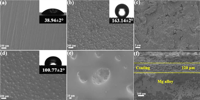
The FE-SEM micrograph of different powder samples was shown in Fig. S2 (Supporting information). The original h-BN shows a layer-by-layer stacking, and each sheet layer with larger and thicker size (Figs. S2a and a1). As shown in Figs. S2b and b1, the MHPS prepared by using spherical SiO2 as the template shows an ordered three-dimensional spherical structure, and after etching with 10 wt% HF acid solution, the spherical structure does not appear to collapse, which provides favorable conditions for the subsequent preparation of SLIPS. Subsequently, positive and negative charge attraction effect between MHPS and h-BN-OH allows MHPS to be embedded in the stacked h-BN lamellar structure thus achieving the effect of exfoliating h-BN. The Figs. S2c and c1 show that the MHPS are successfully embedded in the h-BN nanosheets, which makes the h-BN nanosheets smaller in size and thinner in thickness. Meanwhile, it can be observed at high magnification that the MHPS/h-BN-OH powder has a rich micro-nano porous structure formed by embedding MHPS into h-BN nanosheets. Most importantly, the dimension of the micro/nanostructures is 41.9 nm (Fig. S3c in Supporting information), which consists of MHPS with a particle size of 174.2 nm (Fig. S3a in Supporting information) and h-BN with a lamella thickness of 74.4 nm (Fig. S3b in Supporting information). The synergistic effect of the porous structure and the MHPS ensures that a large amount of lubricant is locked in the surface. In addition, measurement of surface area and pore structure analysis performed via nitrogen adsorption confirmed these results. The FE-SEM technique was applied to observe the surface morphological characteristics of the original Mg alloy, the SHS and the SLIPS. The surface morphology of the original Mg alloy was shown in Fig. 2a, which clearly shows the minor scratches resulting from sandpaper polishing of the surface on the untreated Mg alloy. Besides, the water contact angle (WCA) of the original Mg alloy is only 38.94° ± 2°. The MHPS/h-BN-OH composite was sprayed to the Mg alloy surface by spraying method. As shown in Fig. 2b, the composite was uniformly covered on the Mg alloy surface and formed micro-nanoscale bumps like the lotus leaf surface. The micro-nanoscale porous structures of SHS were observed at high magnification (Fig. 2c). The WCA of the SHS reaches 163.14° ± 2° with the synergistic effect of the micro-nanoscale bumps and the low surface energy material modifications. As shown in Fig. 2d, the SLIPS is denser compared to the SHS coating after the silicone oil injection. The original porous structure was found to disappear at high magnification (Fig. 2e). The formation of the silicone oil layer is because the fact that MHPS as a hollow polypyrrole spheres with mesoporous can locks the lubricant inside the sphere, and the MHPS insert h-BN-OH also forms a large number of pores to store the silicone oil. The movement state of the liquid on the SLIPS has changed from rolling to sliding compare with the rolling behaviors of the droplets on the SHS. Therefore, the WCA of the SLIPS coating decreases, but still maintains an excellent water repellency, and the WCA reaches 100.77° ± 2° and water sliding angle (SA) of 4° (Fig. S4 in Supporting information). Furthermore, the cross-sectional view (Fig. 2f) of the SHS shows that the thickness of the SLIPS coating is 120 µm. Fig. S5 (Supporting information) shows a 3D surface contour view of the SHS. The 3D hierarchical micro-nanoscale porous rough structures with the root mean square (Rms) roughness approximately 620.7 nm.
The chemical bonds or functional groups of h-BN, h-BN-OH, MHPS and h-BN/MHPS powder were characterized by Fourier transform infrared (FTIR) spectroscopy. As illustrated in Fig. S6a (Supporting information), the intense absorption peaks at 1378 cm−1 and 820 cm−1 are caused by the in-plane stretching vibration of the B-N bond and the out-of-plane bending vibration of B-N-B. The minor absorption peak at 2923 cm−1 may be a -CH2- symmetric stretching vibration peak due to the mixing of organic impurities. Moreover, a broad absorption band appears at 3442 cm−1 probably due to the stretching vibration of O-H, and the peak at 3442 cm−1 of h-BN-OH modified by hydroxyl groups is significantly larger and the peak domain is wider than that before the modification, which indicates that h-BN was successfully modified [28]. For the MHPS, the absorption band at 850 cm−1 was caused by C-H out-of-plane deformation vibration. The absorption peak at 1179 cm−1 was due to the stretching vibration of C-N. The appearance of absorption bands at 1551 cm−1 and 1462 cm−1 were attributed to the fundamental vibration of the pyrrole rings [29]. It is noteworthy that a new characteristic peak belonging to MHPS appears in the FT-IR spectrum of MHPS/h-BN. This result indicates the successful combination of h-BN and MHPS. Fig. S6b (Supporting information) is the XRD patterns of h-BN, h-BN-OH, MHPS and h-BN/MHPS. As seen in Fig. S6b, the original h-BN has distinct characteristic peaks at 2θ = 26.43°, 41.30°, 43.39° and 54.67° which match perfectly with the positions of the characteristic peaks of (002), (100), (101) and (004) crystal surfaces on the PDF card of h-BN thus indicating the h-BN belongs to the hexagonal phase crystal structure [30]. After the NaOH modification, the characteristic diffraction peaks of h-BN-OH are in the same position as the characteristic diffraction peaks of h-BN and without impurity peaks, but the intensity of the peak is decreased. This result indicates that although the purity of h-BN is higher after the hydroxyl modification, the crystal structure is affected. The (002) crystal face strength of MHPS/h-BN-OH is significantly reduced by comparing the XRD patterns of h-BN and MHPS/h-BN-OH, indicating a decrease in the number of ordered stacked layers in the c-axis direction of the hexagonal crystal system [31]. According to Scherrer formula [32], the width of the diffraction peak about half-peak height is proportional to the average grain thickness, and the decrease of the diffraction peak (002) indicates that the original h-BN is successfully stripped through the MHPS intercalation. Besides, the MHPS has broad characteristic peaks at 2θ = 23°, which is characteristic peaks of PPy, indicating that MHPS has an orthogonal crystal system structure with space group Fddd.
The porosity of the MHPS and MHPS/h-BN-OH samples was determined by BET testing at 77.3 K. As shown in Figs. S7a and b (Supporting information), the Nitrogen adsorption-desorption isotherm of both MHPS and MHPS/h-BN-OH samples are type Ⅳ and the small H3 hysteresis loop indicates that MHPS and MHPS/h-BN-OH have distinct mesoporous characteristics. At low pressures of 0–0.1 relative pressure the isotherm is biased towards the Y-axis indicating that the samples have a strong interaction with nitrogen. At high pressures of 0.9–1.0 relative pressure the MHPS and MHPS/h-BN-OH samples show a high N2 adsorption behavior indicating the presence of some macroporous structures in the samples. The pore size distribution curves for MHPS and MHPS/h-BN-OH samples calculated from the Barrett-Joyner-Hallender (BJH) model are shown in Figs. S7c and d (Supporting information). From the pore size distribution curves, the MHPS and MHPS/h-BN-OH samples have a continuous pore size distribution and that the pore sizes are mainly concentrated below 500 Å. Moreover, the MHPS/h-BN-OH samples showed significantly more mesoporous structures than MHPS indicating that MHPS intercalated h-BN-OH to form a new mesoporous structure. The average pore size of the MHPS and MHPS/h-BN-OH samples was 130.846 Å and 141.909 Å respectively. The BET surface area of the MHPS and MHPS/h-BN-OH samples were 34.7906 m²/g and 31.5026 m²/g. The BET test results show that both MHPS and MHPS/h-BN-OH are mesoporous structures. Thus, the multiple mesoporous structures formed by MHPS and MHPS/h-BN-OH are beneficial for the silicone oil injection and locking.
Currently, most of the reported mechanical properties of SHS were poor since the papillary micro-nano structures onto the rough surface ware easily damaged. Therefore, the SLIPS as a new type of coating based on SHS, and the mechanical stability of the SLIPS coating becomes an important indicator to evaluate the suitability of the coating for industrial applications [33,34]. The mechanical stability of SHS was assessed via a sandpaper friction test. As shown in Fig. S8a (Supporting information), the SHS was pulled 10 cm back and forth on 800 grits SiC sandpaper after a 100 g weight was pressed on the back of the Mg alloy. A rubbing cycle of 10 cm is taken as pushing back and forth on the sandpaper. Fig. S8b (Supporting information) records the WCA of the SHS at different stages after 50 cycles of friction. It can be clearly seen that the WCA of the SHS is always greater than 150° during the process of 50 friction cycle. The slight increase in WCA after 20 and 40 friction cycles is due to the increased surface roughness of the SHS after sandpaper friction.
For the practical application of Mg alloy, whether the coating applied to the surface of Mg alloy has good anti-contaminant performance is particularly important. As shown in Fig. S9 (Supporting information), the anti-contaminant properties of SLIPS are evaluated by simulating the contamination sources in real life by using different liquids. As can be seen from the images inserted in the upper right corner of Figs. S9a–d, different liquid contaminants (a. methylene blue stained water, b. fruit juice, c. milk, d. muddy water mixture) remain on the surface of the original Mg alloy and cannot be slid off, resulting in different degrees of contamination on the surface of the Mg alloy. However, after the bare Mg alloy was covered with the SLIPS, the droplets slid off quickly and without leave any traces on the coating surface when droplets of contaminants fell on the coating surface (Figs. S9a-a2). Simulated contaminant droplet sloshing tests have shown that SLIPS has excellent anti-contaminant properties due to the excellent water repellency of the coating and the unique super-grease properties of the silicone oil layer. The special silicone oil layer of the SLIPS coating effectively prevents the adhesion of ice to the Mg alloy in low temperature environments. Fig. S10 (Supporting information) shows a simple anti-icing experiment for bare Mg alloy, SHS and SLIPS. The three samples were inserted vertically into a beaker containing a small amount of ice and then filled with water and stored at −15 ℃ for 24 h. After 24 h of freezing, the bare Mg alloy and SHS are firmly frozen in the ice, only the SLIPS coating can be easily taken out. After taking out the SLIPS form the ice, the SLIPS surface still retains sufficient silicone oil and leaves unbroken holes in the ice. The SLIPS obtains anti-icing properties based on three reasons: (1) The presence of a silicone oil layer reduces the contact of the coating with water, resulting in less ice adhesion after freezing. (2) The injection of silicone oil makes the coating super-smooth and thus does not provide the pinning points required for water to freeze. (3) Even after ice has formed, it can be easily removed due to the super-smooth nature of the SLIPS. The simple anti-icing test above shows that the SLIPS coating has excellent anti-icing properties.
To examine the original anti-corrosion capabilities of the SLIPS, EIS plots and Tafel graph of Mg alloy and SHS were performed separately by electrochemical workstation for comparison. The potential dynamic polarization curve of the bare Mg alloy, SHS and SLIPS are shown in Fig. S11 (Supporting information). In addition, the polarization parameters are displayed in Table S1 (Supporting information, corrosion potential (Ecorr), corrosion current density (icorr) and polarization resistance (Rp)), where icorr is calculated by extrapolation, Ecorr is obtained by electrochemical workstation analysis software, and Rp is calculated by Eq. 1 [35].
|
|
(1) |
The βa and βc in the equation respectively refer to the anodic and cathodic Tafel slopes. The 2.303 is a constant.
The Ecorr of bare Mg alloy is −1.47 V and the icorr is 1.09 × 10⁻⁴ A/cm2. The SHS obtained by uniformly spraying MHPS/h-BN-OH composite material modified with silane coupling agent on the bare Mg alloy surface by spraying method which has Ecorr of −1.46 V and icorr of 1.40 × 10⁻⁵ A/cm2. Then, after the silicone oil is infused in the SHS coating to form SLIPS with an Ecorr of −1.81 V and icorr of 9.20 × 10⁻⁶ A/cm2. It is known from the principle of metal corrosion electrochemistry that although Ecorr cannot be used to evaluate the corrosion resistance of a coating, it can illustrate the corrosion thermodynamic tendency of a coating. Generally, the larger the Ecorr value, the lower the corrosion thermodynamic tendency of the coating. However, the Ecorr of the SLIPS was moved to lower direction (more negative) indicating that the cathodic reaction responsible for causing corrosion of the metal is inhibited, or the inhibition of the cathodic reaction is greater than the anodic reaction. Generally speaking, the lower icorr value means the lower the corrosion rate of the coating and better corrosion resistance [36]. The icorr of SLIPS is 2 orders of magnitude lower than that of the bare Mg alloy because the silicone oil is locked in the SHS, which indicates that SLIPS has favorable corrosion resistance. At the same time, the Rp is also an important indicator to evaluate the corrosion resistance of the coating. The larger the Rp value, the better the corrosion resistance of the coating. The Rp value of SLIPS coating is significantly higher than bare Mg alloy and SHS. To sum up, SLIPS coating can effectively protect Mg alloy from corrosion.
In order to better illustrate the corrosion resistance of the SLIPS, the EIS results were adopted to further analyze for different coatings. In general, the larger the radius of the capacitive circle in the Nyquist plot indicates the better corrosion resistance of the sample [37]. The Nyquist plots of original Mg alloy presents two distinct capacitive loops, including a capacitive loop in the high frequency region indicating charge transfer and an inductive loop in the low frequency region corresponding to matter transfer (Fig. S12 in Supporting information). As demonstrated in Fig. 3a, the presence of an inductive loop indicates the dissolution of the Mg alloy in a 3.5 wt% NaCl solution and the transfer of material which mean severe corrosion of the Mg alloy occurred. After 2 h of immersion in a 3.5 wt% NaCl solution, the impedance of SHS increased by 3 orders of magnitude compared to bare Mg alloy as MHPS/h-BN-OH was uniformly sprayed on the Mg alloy.
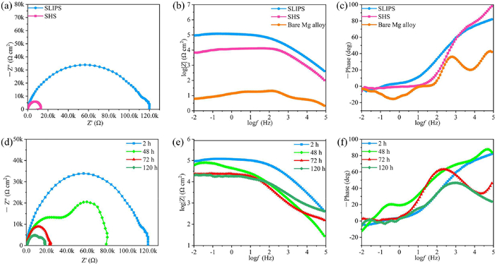
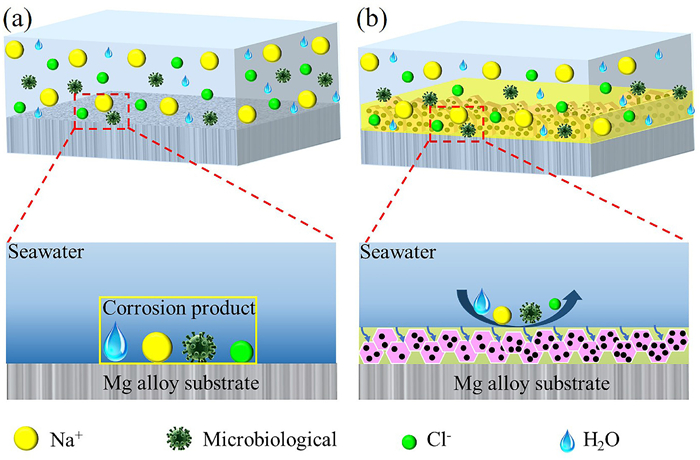
The insertion of MHPS into the h-BN allows the h-BN to peel off and thus form a unique labyrinth structure which prolongs the attack path of corrosive ions on the Mg alloy. In addition, the impedance of the SLIPS is increased by 4 orders of magnitude compared to bare Mg alloy, reaching 1.2 × 10⁵ Ω cm2, which is due to the dense coating made possible by the silicone oil injected into the rough porous structure of the SHS. In the EIS results, Bode-module plots and Bode-phase plots can equally be used to characterizes the corrosion resistance of a coating. In the Bode-module plots, the impedance in the high frequency region is often related to the denseness of the coating, while the impedance in the low frequency region is related to the corrosion resistance of the coating. As shown in Figs. 3b and c, the impedance modulus (|Z|0.01 Hz) of SLIPS is significantly greater than bare Mg alloy and SHS at the low frequency region, indicating that the SLIPS coating can block corrosive ions to a large extent and has excellent anti-corrosion properties. And the Bode-phase plots shows that the phase angle value of the SLIPS layer at the high frequency region is much larger than that of bare Mg alloy. In summary, the reason for the excellent corrosion resistance of the SLIPS is on the one hand due to the excellent corrosion resistance of h-BN-OH and MHPS as raw materials for the coating preparation and on the other hand the formation of the silicone oil film further improves the isolation properties of the coating and greatly prevents the damage of the corrosive ions to the Mg alloy. Therefore, the SLIPS provides high resistance to corrosive media through the synergistic effect of the MHPS/h-BN-OH composite and the silicone oil layer. In practical production and life, there are stringent requirements for the long-term corrosion resistance of metal anti-corrosion coatings. Consequently, the long-term corrosion resistance of SLIPS in 3.5 wt% NaCl solution was characterized by EIS as shown in Figs. 3d–f. It is evident from Fig. 3d that the capacitive arc of the SLIPS coating gradually decreases as the immersion time increases. The gradual decrease in the radius of the capacitance arc demonstrates that with increasing immersion time, corrosive ions gradually penetrate the SLIPS coating resulting in a deterioration of the physical barrier properties and a weakening of the anti-corrosion performance. However, the impedance value of SLIPS was 2 × 10⁴ Ω cm2 after an immersion time of up to 120 h, which was still three orders of magnitude higher than the initial blank sample. Moreover, the bode-module plots and bode-phase plots of the SLIPS coating is shown in Figs. 3e and f. The bode-module plots show that the |Z|0.01 Hz of the SLIPS changed slightly after 48 h of immersion, which indicates that the corrosion protection properties of the coating remained unchanged after 48 h of immersion in the 3.5 wt% NaCl solution compared to the initial immersion, and the silicone oil layer of SLIPS was undamaged and could still prevent the penetration of corrosive media to a large extent. The |Z|0.01 Hz decreased with increasing immersion time. However, even after 120 h of immersion, the impedance modulus in the low frequency region of the SLIPS is still much higher than that of the bare Mg alloy. The Bode-phase plots show that the maximum phase angle after 120 h immersion is approximately the same as at the beginning of the immersion, demonstrating excellent long-term corrosion resistance. The decrease in phase angle after 72 h immersion may be due to the difficulty in controlling the pore size formed after the insertion of MHPS in the h-BN-OH, which forms a relatively large pore size and leads to a serious loss of silicone oil during the long-term immersion. Besides, the peaks appear in the mid-frequency region indicate that corrosive ions start to penetrate inside the coating as the immersion time increases. The EIS results of SLIPS immersed in a 3.5 wt% NaCl solution for 2–120 h demonstrate that the coating has good long-term corrosion resistance. The schematic diagram of the corrosion mechanism of bare Mg alloy and the corrosion protection mechanism of SLIPS are illustrated in Fig. 4. As shown in Fig. 4a, the bare Mg alloy corrodes in direct contact with corrosive substances such as Na+, H2O, Cl− and bacterial micro-organisms in a seawater environment. After the Mg alloy has been covered by the SLIPS coating, the mechanism of corrosion protection with the SLIPS coating are mainly as follows. Firstly, the silicone oil is locked in the porous structure of the surface forms a dense silicone oil layer that blocks the entry of corrosive media and the adhesion of microorganisms. Secondly, the complex layer stacking structure of MHPS/h-BN-OH lengthens the attack path of corrosive media after penetrating the silicone oil layer Fig. 4b. Combining the above two aspects, the SLIPS exhibits excellent corrosion protection for Mg alloy. Meanwhile, a comprehensive comparison with recently reported literature on SLIPS with anti-corrosion properties has been conducted as listed in Table S2 (Supporting information).
To sum up, the method of h-BN exfoliation by polymer intercalation differs from the traditional physical exfoliation method. The polymer intercalation method greatly reduces the exfoliation difficulty of h-BN and increases the pore structure of the composite. Furthermore, the PPy, h-BN and silicone lubricants were selected to successfully fabricate SLIPS with excellent mechanical properties, anti-contaminant, anti-icing, and long-term corrosion resistance on magnesium alloys by a simple spraying method and conventional liquid infusion. Electrochemical test results showed that the icorr of the SLIPS was reduced from 1.09 × 10⁻⁴ A/cm2 to 9.20 × 10⁻⁶ A/cm2, which is a reduction of nearly three orders of magnitude. More importantly, the SLIPS exhibited outstanding corrosion protection against the Mg alloy even after immersion in 3.5 wt% NaCl solution for up to 120 h. Furthermore, the SHS maintained a unique superhydrophobicity with a WCA greater than 150° after 50 sandpaper friction cycles exhibiting outstanding mechanical properties. The dense silicone oil layer on the surface of the SLIPS coating not only effectively avoids the adhesion of microorganisms, but also inhibits the intrusion of corrosive media in synergy with the underlying composite material. The environmentally friendly SLIPS are expected to play an important role in the field of metal corrosion protection.
The authors declare that they have no known competing financial interests or personal relationships that could have appeared to influence the work reported in this paper.
This work was financially supported by National Natural Science Foundation of China (Nos. 51872245, 52103269), the Natural Science Key Foundation of Gansu Province, China (No. 23JRRA680), the Excellent Doctoral Student Project of Natural Science Foundation of Gansu Province (No. 23JRRA695), the Gansu Province University Industrial Support Plan Project (No. 2023CYZC-16), and the Science and Technology Development Plan Project of Lanzhou City (No. 2022-2-78). We also thank the Gansu International Scientific and Technological Cooperation Base of Water-Retention Chemical Functional Materials and Longyuan Young Talent for financial support.
Supplementary material associated with this article can be found, in the online version, at doi:
A. Nabera, I.R. Istrate, A.J. Martín, J. Pérez-Ramírez, Green Chem. 25 (2023) 6603–6611. doi: 10.1039/D3GC01053H
P.M. Nowak, Green Chem. 25 (2023) 4625–4640. doi: 10.1039/D3GC00800B
S. Song, H. Yan, M. Cai, et al., Adv. Mater. Technol. 7 (2022) 2101223. doi: 10.1002/admt.202101223
B. Li, S. Xue, P. Mu, J. Li, ACS Appl. Mater. Interfaces 14 (2022) 30192–30204. doi: 10.1021/acsami.2c06447
S. Xue, B. Li, P. Mu, J. Li, Prog. Org. Coat. 170 (2022) 106966. doi: 10.1016/j.porgcoat.2022.106966
E. Boese, Mater. Corros. 53 (2002) 65–66.
A. Bahmani, M. Lotfpour, M. Taghizadeh, W.J. Kim, J. Magnes. Alloy. 10 (2022) 2607–2648. doi: 10.1016/j.jma.2022.09.007
J. Wei, B. Li, L. Jing, et al., Chem. Eng. J. 390 (2020) 124562. doi: 10.1016/j.cej.2020.124562
G. Shi, M. Wu, Q. Zhong, P. Mu, J. Li, Langmuir 37 (2021) 7843–7850. doi: 10.1021/acs.langmuir.1c01216
H. Li, Q. Zhong, Q. Sun, B. Xiang, J. Li, Langmuir 38 (2022) 3493–3500. doi: 10.1021/acs.langmuir.1c03386
C. Ye, Y. Zhu, H. Sun, et al., Chin. Chem. Lett. 32 (2021) 501–505. doi: 10.1016/j.cclet.2020.03.013
X. Fan, S. Song, Y. Shi, et al., Prog. Org. Coat. 178 (2023) 107478. doi: 10.1016/j.porgcoat.2023.107478
M. Wang, L. Zhou, Y. Hou, et al., Chin. Chem. Lett. 31 (2020) 1914–1918. doi: 10.1016/j.cclet.2020.04.059
T.S. Wong, S.H. Kang, S.K.Y. Tang, et al., Nature 477 (2011) 443–447. doi: 10.1038/nature10447
R. Shi, L. Shang, C. Zhou, Y. Zhao, T. Zhang, Exploration 2 (2022) 20210046. doi: 10.1002/EXP.20210046
F.L. Heale, I.P. Parkin, C.J. Carmalt, ACS Appl. Mater. Interfaces 11 (2019) 41804–41812. doi: 10.1021/acsami.9b14160
Y. Long, X. Yin, P. Mu, et al., Chem. Eng. J. 401 (2020) 126137. doi: 10.1016/j.cej.2020.126137
J. Zhang, C. Gu, J. Tu, ACS Appl. Mater. Interfaces 9 (2017) 11247–11257. doi: 10.1021/acsami.7b00972
S. Wang, Y. Zhang, Y. Han, et al., Acc. Chem. Res. 2 (2021) 407–419.
B. Li, X. Yin, S. Xue, P. Mu, J. Li, Appl. Surf. Sci. 580 (2022) 152305. doi: 10.1016/j.apsusc.2021.152305
Z. Chen, G. Zhang, W. Yang, et al., Chem. Eng. J. 393 (2020) 124675. doi: 10.1016/j.cej.2020.124675
F. Li, Z. Zheng, X. Wang, H. Li, Y. Yan, Chem. Eng. J. 440 (2022) 135920. doi: 10.1016/j.cej.2022.135920
K. Wang, L. Shen, N. Wen, Q. Jiang, Compos. Sci. Technol. 228 (2022) 109646. doi: 10.1016/j.compscitech.2022.109646
S. Liu, T.J. Pan, R.F. Wang, Y. Yue, J. Shen, Prog. Org. Coat. 136 (2019) 105237. doi: 10.1016/j.porgcoat.2019.105237
L. An, R. Gu, B. Zhong, Y. Yu, J. Zhang, Cell Rep. Phys. Sci. 3 (2022) 100941. doi: 10.1016/j.xcrp.2022.100941
W. Stöber, A. Fink, E. Bohn, J. Colloid Interface Sci. 26 (1968) 62–69. doi: 10.1016/0021-9797(68)90272-5
X. Wang, X. Ding, H. Zhao, et al., J. Membr. Sci. 602 (2020) 117968. doi: 10.1016/j.memsci.2020.117968
D. Lin, X. Wang, M. Zhang, et al., Compos. B: Eng. 232 (2022) 109624. doi: 10.1016/j.compositesb.2022.109624
X. Li, G. He, Y. Han, et al., J. Colloid Interface Sci. 387 (2012) 39–46. doi: 10.1016/j.jcis.2012.07.071
M. Du, Y. Wu, X. Hao, CrystEngComm 15 (2013) 1782–1786. doi: 10.1039/c2ce26446c
N. Wang, G. Yang, H. Wang, et al., Mater. Today 27 (2019) 33–42. doi: 10.1016/j.mattod.2018.10.039
A.L. Patterson, Phys. Rev. 56 (1939) 978–982. doi: 10.1103/PhysRev.56.978
X. Fan, H. Yan, M. Cai, et al., Compos. B: Eng. 231 (2022) 109581. doi: 10.1016/j.compositesb.2021.109581
M. Cai, X. Fan, H. Yan, et al., Chem. Eng. J. 419 (2021) 130050. doi: 10.1016/j.cej.2021.130050
C.H. Chang, M.H. Hsu, C.J. Weng, et al., J. Mater. Chem. A 4 (2016) 19214–19215. doi: 10.1039/C6TA90243J
C. Ding, J. Xu, L. Tong, et al., ACS Appl. Mater. Interfaces 9 (2017) 21034–21047. doi: 10.1021/acsami.7b06347
F. Peng, H. Li, D. Wang, et al., ACS Appl. Mater. Interfaces 8 (2016) 35033–35044. doi: 10.1021/acsami.6b12974

Figure 2 FE-SEM images of surface appearance of (a) bare Mg alloy, (b, c) SHS coating and (d, e) SLIPS coating at low and high magnification. (f) Cross-section FE-SEM images of SHS. The insets of (a), (b) and (d) are the WCA of the bare Mg alloy, SHS coating and SLIPS coating.

Figure 3 Electrochemical impedance spectra (EIS) results of the bare Mg alloy, SHS and SLIPS coating. (a) Nyquist plots, (b) Bode-module plots, (c) Bode-phase plots. Long-term anti-corrosion properties of SLIPS. (d-f) Nyquist plots, Bode-module plots, and Bode-phase plots after 2 h, 48 h, 72 h and 120 h immersion in 3.5 wt% NaCl solution.

 扫一扫看文章

扫一扫关注我们
 DownLoad:

 下载:
下载:

 下载:
下载: