Figure 1.
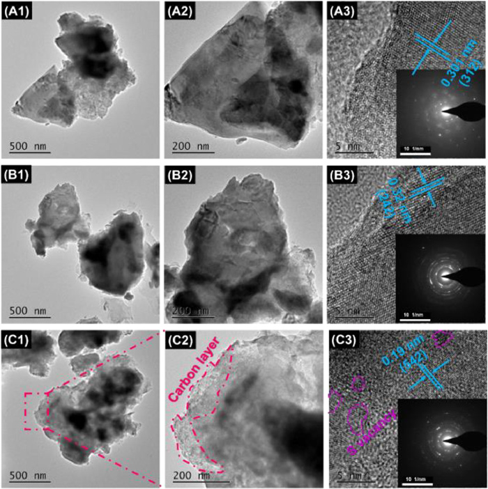
TEM images with different magnification, SAED patterns and HRTEM images for (A1-A3) PCFS, (B1-B3) CFS and (C1-C3) CFS@C.
Interfacial/bulk synergetic effects accelerating charge transferring for advanced lithium-ion capacitors
Chang Liu , Zirui Song , Xinglan Deng , Shihong Xu , Renji Zheng , Wentao Deng , Hongshuai Hou , Guoqiang Zou , Xiaobo Ji

With the ever-increasing concern on the human living environment and the eagerness to search sustainable energy sources, the construction of clean and renewable energy-storage devices is becoming a world-wide important topic [1–15]. With fast development of modern society, the achievements in lithium ion batteries (LIBs) (energy density: 150–200 Wh/kg; power density: <1000 W/kg; and lifespan: <1000 times) and electrochemical capacitors (ECs) (energy density: <10 Wh/kg; power density: >10 kW/kg; and lifespan: 104–105 cycles) are still in an unsatisfactory stage [16–26]. Special energy-storage devices are urgently desired with a high energy density close to LIBs, high power density, and long cycle life rivaling that of ECs, which are recognized as LICs [27–33]. Advanced electrode materials can achieve superior Li+ storage capability and thus are regarded as the main contributions of high-performance LICs. With the necessity to boost the utilization of electrode materials, during the past decade, increasing researchers have focused upon designing and fabricating nanomaterials with controlled morphologies ranging from zero to 3D structures. For example, unique architecture of bundled defect-rich MoS2 offers a 3D electron/ion diffusion with faster kinetics [34,35]. Benefitting from the well-designed 2D configuration, atomically thin Bi2MoO6 sheets are endowed with extraordinary high-rate capability and ultra-long cycling stability [36].
Interfacial engineering and heteroatom doping are also efficient strategies to enhance the charge transferring rate of the electrode materials [37–39]. Hierarchical Bi2S3/MoS2 heterojunction and CoO/Co3S4 heterostructures are reported to realize advanced energy storage [40,41]. Anionic dopant delocalization through p-band modulation is demonstrated to render metal oxides with enhanced electrochemical performances [42]. Nevertheless, confronted with high complexity in synthesis process and low productivity as well as product wastage, it is extremely difficult in achieving quantity production of these chemosynthetic nanostructure materials. Comparatively, natural mineral resources take advantage of cost-effectiveness, environment-benefitting and abundance of mineral wealth, which is entirely in agreement with "Green Chemistry" concept.
In this work, we have put forward an interfacial/bulk synergetic modification strategy to regulate electron migration and ion diffusion among natural bornite materials, expected to realize ultrafast and stable lithium-storage capabilities. Reduction treatment continuously introduces rich vacancies into Cu5FeS4 bulk phase, which can effectively bridge the wide band gap of bornite and thus improve its intrinsic electron conductivity. Meanwhile, CFS@C heterojunction spontaneously evokes a built-in electric field between its interfacial region, accelerating electron migration and ion diffusion. In virtue of sulfur vacancies into bulk phase and CFS@C heterostructure around interfacial region, the designed CFS@C electrode exhibits high specific capacity (822.4 mAh/g at 100 mA/g) and excellent rate capability (376.6 mAh/g at 5 A/g) as anode for LIBs. When combined with PCS cathode, the as-built full LIC shows extraordinary energy-power characteristics of 364.0 Wh/kg at 125 W/kg, along with long-term cycling stability. Additionally, DFT calculations offer in-depth understanding regarding the fast ion transportation in this composite in terms of sulfur introduction as well as hetero-interface construction. It is expected that the co-construction design and interfacial/bulk synergetic modification strategy can be expanded to the development of other natural minerals for energy storage systems.
Field-emission scanning electron microscope (FE-SEM) is conducted to analyzed morphology and structural details of the as-prepared samples. Non-uniform size distributions of raw bornite are shown in Figs. S1A1–C1 (Supporting information), and various size particles range from 0.2 µm to 3 µm. Compared to pure bornite materials in Figs. S1A2–C2 (Supporting information), Cu5FeS4-x is characterized by rich sulfur vacancies (CFS), after NaBH4 reduction treatment, thus leading to rougher surface than pristine Cu5FeS6 (PCFS) along with reduced grain size. As presented in Figs. S1A3–C3 (Supporting information), SEM images show that the average diameter of CFS@C is less than 1 µm, smaller than that of CFS, which can be attributed to carbon coating, effectively preventing from serious agglomeration. In addition, the analysis of energy-dispersive spectroscopy (EDS) element mapping is presented in Figs. S1D1–D3 (Supporting information). It is noted that Cu, Fe, and S elements uniformly distribute in the selected area of the samples. Obviously, the introduced carbon matrix is observed in marked area (red color), loosely stacked around CFS aggregates. However, element mapping results indicate no significant differences between these samples with/without carbon coating, probably caused by superior signals of carbon-based conductive adhesive used in FE-SEM tests. Fig. 1 shows representative TEM images, the typical structural feature of three electrodes are well matched with SEM images. From different magnifications of TEM images (Figs. 1A1 and A2), the untreated bornite sample remains an irregular shape, and some lamellar structure is found at its edge region. As displayed in Figs. 1B1 and B2, some of separated thinner layers are randomly scattered around CFS chunks and smaller particle are aggregated to form these chunks. Different from the other two samples, a poor crystalized thin layer on the CFS@C surface is identified as coated carbon layer, which is tightly wrapped on the surface of PCFS (Figs. 1C1 and C2). Notably, CFS@C is featured by smaller particle size, agreeing well with FE-SEM results. To investigate the structure of CFS@C composite, high resolution transmission electron microscope (HR-TEM) and selected area electron diffraction (SAED) are used to further analyze these as-prepared samples. As shown in Figs. 1A3-C3, HR-TEM image shows different crystal structure characteristics, indicating the existence of multiphase of PCFS and amorphous carbon. Specifically, the lattice space of 0.19 nm is ascribed to (542) plane of CFS@C in Fig. 1C3. Besides, large sulfur vacancies are found in PCFS crystal lattice which is in agreement with CFS crystal structure. Comparatively, the clear lattice fringes are measured to be 0.30 nm, assigned to (312) plane of PCFS. It is noted that CFS shows a broken lattice of 0.32 nm (242), while raw PCFS presents a nearly defect-free crystal (Figs. 1A3 and B3). With regard to SAED patterns, weak diffraction rings are observed in PCFS while brighter polycrystalline diffraction rings are illustrated in the insert patterns of Fig. 1C3, which reveals that the Cu5FeS4 also maintain a high crystalline after reduction calcination treatment.
Crystalline nature and phase composition of the resultant samples are examined by powder X-ray diffraction (XRD). As shown in Fig. 2a, all diffraction peaks of raw bornite can be indexed to the trigonal Cu5FeS4 (ICSD#1963) [43]. However, some impurity peaks of quartz and tenorite minerals are still detected, originating from the oxidation of bornite minerals and the paragenesis of quartz ore. Meanwhile, electron paramagnetic resonance (EPR) is conducted to offer fingerprint evidence for probing sulfur vacancies. Fig. 2b clearly shows a pair of characteristic EPR peaks, the symmetrical signals located at g = 2.0, revealing the presence of isolated sulfur vacancies in the CFS@C crystal structure [44,45]. Thermogravimetric analysis (TGA) was employed to determine the carbon contents of materials (Fig. 2c). For CFS@C composite, the first weight loss below 100 ℃ corresponds to the evaporation of adsorbed water. The slight weight rising around 100 ℃ to 300 ℃ is from the oxidation of Cu5FeS4 phase. With temperature increasing to 1000 ℃, continuation weight loss is noticed, which is caused by carbon dioxide emission and decomposition of copper sulfate and iron sulfate. In comparison to PCFS, the carbon contents of CFS@C are calculated to be 3.29%. The detailed structure of CFS@C heterojunction is further clarified via Raman measurement. Weak Raman signals are found in CFS@C sample, resulted from carbon coating lowering the signals of bond vibration (Fig. 2d). As shown in Fig. 2e, two sharp peaks at ~1364 and ~1588 cm−1 are only observed in CFS@C counterpart, corresponding to the disorder-induced phonon mode (D-band) and graphite band (G-band). The intensity ratio ID/IG for D-band and G-band can roughly describe the defect quantity in CFS@C materials, ID/IG = 1.05 indicating its more disorder structure.
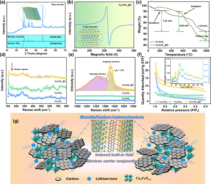
To evaluate the specific surface area and porosity of the as-prepared samples, nitrogen adsorption-desorption isotherm and Barrett-Joyner-Halenda pore-size analysis are implemented (Fig. 2f). Based on the IUPAC classification, the isotherms of the samples present a typical type of Ⅳ isotherms, illustrating the existence of mesopores. It is noted that the specific surface areas for PCFS and CFS are 5.8, 8.7 m2/g, respectively, which are much lower than CFS@C (25.2 m2/g). Average pore sizes of the samples are 18–37 nm, indicating the porous structure of the as-prepared samples. As expected, the introduced carbon framework with porosity and relatively high specific surface area can endow CFS@C heterojunction with large active-material contacting areas with electrolyte and short Li+ diffusion distance during (de)intercalation processes. According to the analyses above, the relevant energy-storage mechanism has been proposed as illustrated in Fig. 2g. Different from other conventional synthetic processes, like solvothermal reactions, chemical vapor deposition, multistep solid-phase sintering etc. the crude minerals directly coming from target mine is considered to be waste free and environmental protection, completely in conformity with "Green Chemistry" idea. The succedent sulfur introduction and carbon coating only require simple reduction treatment and thermal carbonization process. With the presence of SVs and multifunctional carbon matrix, a Cu5FeS4/C heterojunction is constructed and thus built-in electric field is spontaneously evoked at the heterointerface of bornite and carbon. The interfacial as-built electric field can regulate electron migration and boost ion transferring along Cu5FeS4/C interface, enabling fast interfacial charge transport kinetics. Meanwhile, SV implantation exert a vital role in managing atomic orbitals and band gap of Cu5FeS4 bulk phase, accordingly leading to its improved intrinsic electron conductivity. Multi-functioned carbon coating as conductive and protecting matrix can protect from electrolyte erosion and alleviate the volume expansion simultaneously during the repeated charge-discharge processes. In virtue of the interfacial and bulk phase modification, the as-prepared CFS@C is expected to deliver superior Li-storage capacities and excellent long-term cycling stability.
Fourier transform infrared (FTIR) spectrum is applied to further confirm the contribution of carbon coating. As shown in Fig. S2a (Supporting information), these peaks at 1064.5 cm−1 and 668.7 cm−1 respectively, tend to shift towards higher wavenumber, the hypsochromic shift attributed to carbon matrix introduction. Meanwhile, X-ray photoelectron spectroscopy (XPS) measurements are conducted to investigate the electronic states and quantitative surface elemental analysis of Cu, Fe, S and C elements of CFS@C composite. As shown in Fig. S2b (Supporting information), Cu 2p, Fe 2p, O 1s, C 1s, and S 2p orbitals are detected in all three samples. High resolution spectra are further analyzed in Figs. S2c–f (Supporting information). C 1s peaks can be deconvoluted into a dominated component of sp2-C/sp3-C at 284.8 eV (Fig. S2c), C–O at 286.1 eV, and C=O at 289.5 eV, respectively [46,47]. In Cu 2p spectrum (Fig. S2d), two core peaks related to Cu(Ⅰ) 2p3/2/2p1/2 levels are obtained, and the spin-orbit splitting is found to be 19.7 eV, suggesting the existence of Cu+ ions. A pair of peaks located at 934.9/954.6 eV can be assigned to strong satellite signals of 2p3/2/2p1/2, and peaks at 934.1 and 960.8 eV to weak satellite 2p3/2/2p1/2, respectively. The obtained binding energies of Cu(Ⅰ) 2p3/2, Cu(Ⅰ) 2p1/2, and two pairs of shake-up satellites are in good agreement with the reported characteristic Cu peaks of PCFS [48,49]. A couple of core peaks at 713.6/726.4 eV is clearly observed in Fig. S2e, corresponding to Fe(Ⅲ) 2p3/2/2p1/2. Two peaks situated in 710.7/723.5 eV are indexed to Fe(Ⅱ) 2p3/2/2p1/2, which suggests that partial Fe3+ ions are deoxidized due to the charge balance mechanism after sulfur vacancy introduction [50,51]. Two broad peaks at 718.9 and 731.7 eV are related to the satellites of Fe element. The existence of Cu5FeS4 can be further verified by the two evident S signals at 162.7 eV and 169.2 eV in Fig. S2f. After peak fitting, characteristic peaks of S 2p3/2 and 2p1/2 at 162.3 and 163.55 eV [46], respectively, are indexed to S2− ion. A pair of peaks of C-S bonds are marked in CFS@C sample, at 168.8/170.1 eV, respectively. In stark contrast, PCFS and CFS only show S2− signals in the S 2p spectra, which further confirm the successful implantation of carbon matrix. Also, lower binding energy of S 2p3/2 and 2p1/2 is noticed in CFS than pristine Cu5FeS4, mainly due to the existence of rich SVs.
As presented in Fig. 3a, galvanostatic charge-discharge curves of three electrodes, are measured at 100 mA/g in a voltage range of 0.01–3.0 V (vs. Li+/Li). Discharge/charge specific capacities of three electrodes are 407.1/457.4, 520.9/655.0 and 604.7/787.4 mAh/g, respectively, and thus the initial coulombic efficiencies (ICE) are ranked in order of PCFS (89%) > CFS (79.5%) > CFS@C (76.8%). PCFS electrode exhibits higher ICE, which is attributed to its lower specific surface area than those of other two samples and the relatively low lithium storage capacity. CFS@C electrode shows the lowest ICE, which is mainly caused by more electrolyte consumption and solid electrolyte interphase (SEI) formation [1,20,28,52–55]. In the discharge process, there are three plateaus at 1.7, 1.3 and 0.8 V for CFS and CFS@C, while no obvious plateaus is observed in PCFS counterpart. The major charge plateaus of two electrodes appear at 1.8 and 2.3 V, and similarly no evident charge platform for PCFS electrode. To compare the lithium storage performances of three electrode materials, cycling stability and rate performance are further investigated in Figs. 3b and c. It is noted that CFS exhibits better cycle stability and rate performance than that of PCFS electrode, which could be attributed to the much-improved conductivity from the implantation of sulfur vacancies. From Fig. 3b, it can be seen that CFS@C electrode delivers much higher specific capacity and better cycling stability than PCFS and CFS electrodes, which may be attributed to the synergistic effects of sulfur vacancies in bulk phase and the interfacial built-in field evoked by Cu5FeS4/C heterostructure. CFS@C electrode exhibits a high reversible capacity of 822.4 mAh/g after 100 cycles at 100 mA/g, which is superior to those of CFS and PCFS, indicating that the heterostructure can greatly influences their electrochemical performance. In addition to high reversible capacity, the well-designed CFS@C heterostructure is endowed with excellent rate capabilities (Fig. 3c). As current density increases from 0.05 mA/g to 0.1, 0.2, 0.5, 1.0, and 2.0 mA/g, CFS@C electrode delivers average discharge capacities of 684.4, 678.2, 676.6, 635.6, 586.4, and 506.7 mAh/g, respectively. Even at a large current density of 5.0 A/g, the electrode can still exhibit remarkable reversible capacity of 375.2 mAh/g. In contrast, PCFS electrode shows poor rate performance of less than 200 mAh/g at 5 A/g, which is inferior to CFS electrode. Charge-discharge profiles of CFS@C at different current densities show slight shifting and small over-potential as the current density increases, further verifying its superior rate performance (Fig. 3d), according well with the Li+ diffusion coefficient results during charging/discharging processes (Figs. 3e and f). However, PCFS electrode presents severe derivation and fast capacity fading with the increasement of current densities in Fig. 3c, in good agreement with the above rate performance results.
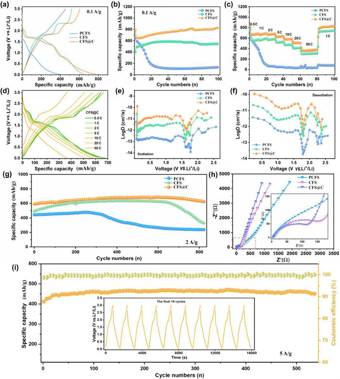
As shown in Fig. 3g, cycling performances of these electrodes tested at 2 A/g demonstrate that PCFS electrode suffers quick capacity decay due to its intrinsic poor conductivity and serious volume change during redox reaction processes. CFS electrode obtains the relatively high specific capacity of 328.4 mAh/g after 800 cycles, while it still exhibits unsatisfactory cycling stability, resulted from huge volume expansion and structural pulverization during the repeated (de)lithiation. Comparatively, CFS@C electrode delivers both high reversible capacities of 622.7 mAh/g after 820 cycles and excellent cycling stability at 2 A/g. Besides, Electrochemical impedance spectroscopy (EIS) results are shown in Fig. 3h, revealing that CFS@C shows the smallest charge transfer resistance, suggesting its fast charge transfer kinetics. As respected, even at a larger current density of 5 A/g, the reversible lithium storage capacity is retained at 447 mAh/g after 540 loops (Fig. 3i). The systematic electrochemical curves indicate that the as-obtained CFS@C composite can simultaneously achieve enhancements in their capacity, cycling stability, and rate capability.
Benefit from the integration of the interfacial as-built electric field and SV implantation into bulk phase, the well-designed CFS@C heterostructure is endowed with extraordinary electrochemical performances. To further explore detailed energy storage mechanism, CV profiles of electrode materials are evaluated at a scan rate of 0.1 mV/s. As delivered in Fig. S3a (Supporting information), there are two evident pairs of redox peaks of R1/O1 (1.93/1.6 V) and R2/O2 (2.39/2.1 V) in the first scan. A broad peak at 0.62 V appears in the first scan and disappears after following scans, which results from electrolyte reduction decomposition and SEI formation. Besides, the broad peak located at 0.5–1.0 V can be attributed to the surface energy storage through pseudo capacitance behavior [16,56,57]. In the subsequent scans, CV profiles show good reproducibility, suggesting the good reversibility of electrochemical redox reactions. Four CV cycles are gradually broadened, consistent with the capacity increase phenomenon in rate capability tests. According to previous reports, the energy storage mechanism is not only dominated by diffusion-controlled behavior, but controlled by surface capacitive contribution. Pseudo capacitance contribution could be calculated by separating the diffusion-controlled capacity and capacitive capacity at different scan rates of 0.1–3.0 mV/s. Different CV profiles of three electrodes are exhibited in Fig. S3b (Supporting information), and obviously the shapes of CFS@C and CFS are well preserved with increasing scan rate. Notably, redox peaks of CFS@C only show a slight shift with the increasing of scan rates, but the capacity is still reversible. CV curves of PCFS tend to deviate from its original shape, showing great potential polarization. The capacity contribution mechanism can be quantized according to Eqs. 1 and 2 [57,58].
|
|
(1) |
|
|
(2) |
The fitting b value at various scan rates could reveal the lithium storage kinetics. Generally, a strictly diffusion-limited reaction is identified when b value is close to 0.5. While the reaction is considered as surface capacitive driven, when b value are close to 1 [59]. Hence, Peak O1/R1 and Peak R2/O2 are selected and the peak currents are recorded to evaluate relevant b values. As shown in Fig. S3c (Supporting information), for Peak R1/O1, the fitting b constants are 0.21/0.01 (PCFS), 0.57/0.39 (CFS) and 0.58/0.59 (CFS@C), respectively, the b value close to 0.5 suggesting a diffusion-predominant kinetics [58]. In contrast, these fitting b values from Peak O2/R2 are 0.77/0.23, 0.84/0.74 and 0.88/0.75, respectively, and the larger b values indicate more capacitive-controlled behaviors. In addition, voltammetric sweep rates dependence have been conducted to quantitatively determine pseudocapacitive capacitive contribution to the current response (Eqs. 3 and 4) [58–60].
|
|
(3) |
|
|
(4) |
k1ν in Eq. 3 represents the current attributed to intercalation/conversion behavior and k2ν1/2 is associated with the diffusion-limited current. With detailed calculation, 49.6%, 59.2% and 61.1% (Fig. S3d in Supporting information) of total capacity are identified as surface-controlled capacitive contribution for PCFS, CFS, and CFS@C, at 0.3 mV/s. And capacitive contribution rates are obviously improved from 53.5% at 0.1 mV/s to 83.9% at 3.0 mV/s for CFS@C.
To deeply understand the significant effects of rich sulfur vacancies and heterojunction on the high capacity of CFS@C, computational explorations of structural and electronic properties have been conducted on different structure models. In our calculations, crystalline Cu5FeS4 model is simulated by adopting density functional theory (DFT) method to evaluate electronic/charge distribution structure. Through the as-built simulation model, PCFS and CFS@C heterostructure are constructed (Fig. S4 in Supporting information), and the density of states (DOS) are calculated. According to DOS patterns in Figs. S5a and b (Supporting information), Fermi level results reveal that a wide band gap occurs in PCFS model, indicating poor electronic conductivity of bulk Cu5FeS4 phase. Meanwhile, in CFS@C heterojunction structure, the density of states crosses the Fermi level and no obvious band gap is found at the Fermi level based on interfacial positions, which illustrates that electron structures reshape at the heterostructure interface. The DFT calculated results suggest that the heterojunction structure can enhance the electronic conductivity of Cu5FeS4, thus contributing to the fast reaction kinetics to some extent. Li-ion diffusion mechanism in CFS@C is investigated by conducting DFT calculations to compare Li+ diffusion barrier energies in Cu5FeS4 with or without carbon coating (Fig. S5c in Supporting information). For PCFS model, two different diffusion pathways are identified along path a1 and a2 in Fig. S5d (Supporting information). Different diffusion energy paths in CFS@C heterostructure interface are recognized as path b1-b4 (Fig. S5e in Supporting information), respectively. As shown in Fig. S5c, the energy barrier for Li+ diffusion in all diffusion paths of CFS@C heterojunction is calculated to be 0.75 eV, much lower than that in PCFS model (1.27 eV). The above-mentioned diffusion barrier results demonstrate that CFS@C heterostructure can effectively decrease diffusion energy barrier of Li ion, and thus accelerate Li+ diffusion kinetics. As reported in previous works, the intimate contact of different semiconductors could induce unbalance charge distribution between Cu5FeS4 bulk and carbon matrix, thus forming the built-in electric field as the Fermi level reach balance through spontaneous carrier migration. By using the built model, charge density difference is obtained through the simulation calculation, which is further used to explore the charge distribution characteristics of CFS@C heterostructure. It is note that the constructed 3D charge density difference patterns are shown in Figs. S6 and S7 (Supporting information), for PCFS and CFS@C, respectively. As shown in Fig. S6, the imbalanced charge distribution is noticed in CFS@C heterojunction, which generates electron migration from Cu5FeS4 side to conductive carbon side. To further study the effects of oxygen replacing sulfur atoms in theory, CFS@C model with O substitution is displayed and analyzed in Fig. S8 (Supporting information). Obviously, with oxygen substitution for sulfur, higher electron cloud density is marked around the existed oxygen atoms in CFS@C model. The richer electron domain originates from greater electronegativity of oxygen than that of sulfur element.
After systematic analyses of Li-storage performances in half cells, electrochemical properties of lithium ion capacitors are further investigated to reveal the well-designed structural advantages. Herein, ethylenediaminetetraacetic acid dipotassium salt dehydrate (EDTA-2K·2H2O) is exclusively selected to prepare carbon cathode materials and the obtained PCS show sheet-like morphology with a continuous sheet-like structure in Fig. S9 (Supporting information), after carbonization of EDTA-2K·2H2O followed by KOH activation (the detail information is shown in the Experimental Section in Supporting information). For XRD pattern of PCS cathode, its (002) peak is very weak and broad after KOH activation, indicating its typical amorphous feature (Fig. S10 in Supporting information). Two intense peaks centered at 1350 and 1600 cm−1 in Raman spectrum are recognized as D- and G-bands, respectively (Fig. S11 in Supporting information). The ratio of IG/ID was about 1.6, suggesting that PCS is of low degree of graphitization, well coinciding with HRTEM images in Fig. S12 (Supporting information). XPS results indicate that PCS cathode is primarily constitutive of carbon, oxygen, and nitrogen elements (Fig. S13 in Supporting information). As presented in Fig. S14 (Supporting information), the high-resolution C 1s signal can be divided into C–C/C=C (284.8 eV), C–O/C=O (288.9 eV), O–C=O (291.5 eV) and C–N (286.1 eV), and N 1s can be divided into graphitic-N, pyrrolic-N, and pyridinic-N [60], respectively. Meanwhile, PCS cathode shows typical type Ⅳ adsorption-desorption isotherms (Fig. S15 in Supporting information), along with an extremely high surface area of 2357.8 m2/g. Electrochemical performances of PCS cathode are further analyzed in a half-cell configuration against Li metal at 2–4.5 V, which will be employed as a capacitive-adsorption electrode for LIC. CV curves shown in Fig. S16 (Supporting information) show a broad rectangular box-like shape, indicating a surface anion storage in PCS cathode. On positive polarization, PCS cathode could reversibly adsorb ClO4 anion and release Li cations. However, on negative polarization the rectangular shape curve is slightly distorted near 3.0 V due to the limited accessibility of cations into pores, which is quite pronounced for Li+-based system. Charge-discharge curves of PCS cathode in Fig. S17 (Supporting information) exhibit relatively straight and flat profile due to the reversible adsorption/desorption of ClO4 anions over the pores of PCS cathode. PCS delivers a high capacity of ≈100 mAh/g at 0.1 A/g and the majority of obtained capacity is originated from double-layer formation of ClO4 anion. With an increase in current density, the charge-discharge curves still maintain the original shape profile without any obvious distortion. Under 2 A/g, PCS exhibit a high capacitance of ≈73.2 mAh/g (Fig. S18 in Supporting information), while conventional activated carbon and other porous carbon materials fail to work. The high capacity values evidence the enhanced adsorption kinetics of PCS cathode with its 3D hierarchical architecture and large pore volume.
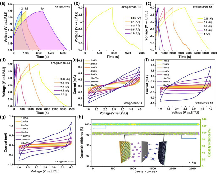
To minimize the irreversible capacity loss, CFS@C electrode is prelithiated at 50 mA/g for 5 cycles before LIC cell assembly. Lithium ion capacitors are operated between 1.0 V and 4.0 V to evaluate the electrochemical properties. Considering that different energy-storage mechanisms in battery-typed anode and capacitive cathode, the mass ratio of CFS@C anode and PCS cathode should be optimized to balance charge transport kinetics. As for GCD profiles in Fig. 4a, the as-built LICs are performed under different anode/cathode mass radios (1:2, 1:4 and 1:6). Particularly, when the mass radio is set as 1:2 (Fig. 4b), the relatively low capacitance is obtained, which is much lower than that of the optimal LIC with 1:4. Nevertheless, with mass ratio of 1:6, the obtained capacitance is improved, nevertheless, still inferior to the optimized LIC. As shown in Fig. 4c, for the optimized LIC of 1:4, GCD curves are approximately in a trend of linear at various rates. Such symmetric discharge and charge curves suggest a good reversibility and a high CE. In comparison, both LIC with 1:2 and 1:6 present rather low capacities with the incensement of current densities in Figs. 4b and d. Based on total mass of two electrodes, the maximum energy densities are calculated as 364.0 Wh/kg at 125 W/kg in the optimal LIC. According to calculation Eq. S3.1 (Supporting information), energy densities of 139.2 Wh/kg is achieved at high power densities of 2500 W/kg. CV profiles of LICs at different scan rates are shown in Figs. 4e–g. By comparison with other two ratios, the shapes of CV curves slightly deviate from a rectangular-like shape with scan rates increase from 1 mV/s to 50 mV/s, due to the different charge storage mechanisms of two electrodes, while the similar shape of CV curves is retained without obvious polarization. Furthermore, cycling stability of the optimal CFS@C//PCS device is evaluated at 1 A/g (Fig. 4h). It is found that the capacity retention is over 98.2% after 2640 cycles with high CEs (≈100%) during the whole cycling process, indicating the excellent reversibility and stability of the constructed CFS@C//PCS device. Obviously, the optimal CFS@C//PCS LIC well overcomes the intrinsic kinetics and capacity mismatch, which is considered as a promising energy storage device with good combination between high energy density and stable cycle life.
In summary, an interfacial/bulk synergetic modification strategy have been successfully introduced to regulate electron migration and ion diffusion among natural bornite materials, expected to realize ultrafast and stable lithium-storage capabilities, in which rich vacancies in Cu5FeS4 bulk phase can effectively bridge the wide band gap of bornite and thus improve its intrinsic electron conductivity, Meanwhile, CFS@C heterojunction spontaneously evokes a built-in electric field between its interfacial region, largely reducing the migration barrier of Li+. Remarkably, the designed CFS@C electrode exhibits high specific capacity of 822.4 mAh/g at 100 mA/g and excellent rate capability of 376.6 mAh/g at 5 A/g as anode for LIBs. When combined with PCS cathode, the as-built full LIC presents extraordinary energy-power characteristics of 364.0 Wh/kg at 125 W/kg, along with long-term cycling stability. The co-construction design and interfacial/bulk synergetic modification strategy in this work can be expanded to the development of other natural minerals for energy storage systems.
The authors declare that we have no known competing financial interests or personal relationships that could have appeared to influence the work reported in this paper.
This work was supported by the National Natural Science Foundation of China (Nos. 52004338, 22378431), Hunan Provincial Natural Science Foundation (Nos. 2022JJ20075, 2023JJ40210), Scientific Research Fund of Hunan Provincial Education Department (No. 21B0017), Central South University Innovation-Driven Research Programme (No. 2023CXQD008).
Supplementary material associated with this article can be found, in the online version, at doi:
P. Albertus, S. Babinec, S. Litzelman, A. Newman, Nat. Energy 3 (2018) 16–21.
K. Zou, W. Deng, P. Cai, et al., Adv. Funct. Mater. 31 (2021) 2005581. doi: 10.1002/adfm.202005581
P. Cai, K. Zou, X. Deng, et al., Adv. Energy Mater. 11 (2021) 2003804. doi: 10.1002/aenm.202003804
P. Cai, R. Momen, Y. Tian, et al., Adv. Energy Mater. 12 (2022) 2103221. doi: 10.1002/aenm.202103221
E. Lim, C. Jo, M.S. Kim, et al., Adv. Funct. Mater. 26 (2016) 3711–3719. doi: 10.1002/adfm.201505548
A. Indra, T. Song, U. Paik, Adv. Mater. 30 (2018) 1705146. doi: 10.1002/adma.201705146
Y. Sha, Z. Zhang, Y. Chen, et al., Electrochim. Acta 222 (2016) 587–595. doi: 10.1016/j.electacta.2016.11.013
Z. Cao, H. Zhang, B. Song, et al., Adv. Funct. Mater. 33 (2023) 2300339. doi: 10.1002/adfm.202300339
S. Tao, J. Cai, Z. Cao, et al., Adv. Energy Mater. 13 (2023) 2301653. doi: 10.1002/aenm.202301653
K. Krishnamoorthy, P. Pazhamalai, S. Manoharan, et al., Carbon Energy 4 (2022) 833–855. doi: 10.1002/cey2.202
Y. Na, X. Sun, A. Fan, et al., Chin. Chem. Lett. 32 (2021) 973–982. doi: 10.1016/j.cclet.2020.09.007
N.T. Aristote, K. Zou, A. Di, et al., Chin. Chem. Lett. 33 (2022) 730–742. doi: 10.1016/j.cclet.2021.08.049
M. Yang, Q. Ning, C. Fan, X. Wu, Chin. Chem. Lett. 32 (2021) 895–899. doi: 10.1016/j.cclet.2020.07.014
C. Liu, L. Deng, X. Li, et al., Electrochem. Commun. 150 (2023) 107491. doi: 10.1016/j.elecom.2023.107491
J. Yuan, N. Qin, Y. Lu, et al., Chin. Chem. Lett. 33 (2022) 3889–3893. doi: 10.1016/j.cclet.2021.11.062
Y. Liu, X. Xu, Z. Shao, S.P. Jiang, Energy Storage Mater. 26 (2020) 1–22. doi: 10.1016/j.ensm.2019.12.019
D. Xiong, L. Yang, Z. Cao, et al., Adv. Funct. Mater. 33 (2023) 2301530. doi: 10.1002/adfm.202301530
S. Tao, R. Momen, Z. Luo, et al., Small 19 (2023) 2207975. doi: 10.1002/smll.202207975
Z. Song, G. Zhang, X. Deng, et al., Adv. Funct. Mater. 32 (2022) 2205453. doi: 10.1002/adfm.202205453
C. Liu, X. Fu, S. Liao, et al., Nanomaterials 13 (2023) 254. doi: 10.3390/nano13020254
X. Deng, Y. Tian, K. Zou, et al., Carbon Energy 4 (2022) 1151–1168. doi: 10.1002/cey2.209
D. Xiong, X. Deng, Z. Cao, et al., Energy Environ. Mater. (2023) e12521. doi: 10.1002/eem2.12521
M.S. Javed, S. Asim, T. Najam, et al., Carbon Energy 5 (2023) e271. doi: 10.1002/cey2.271
M. Zhong, M. Zhang, X. Li, Carbon Energy 4 (2022) 950–985. doi: 10.1002/cey2.219
Z. Cao, R. Momen, S. Tao, et al., Nano-Micro Lett. 14 (2022) 181. doi: 10.1007/s40820-022-00910-9
T. Zhang, P. Zhang, Z. Liao, et al., Chin. Chem. Lett. 33 (2022) 3921–3924. doi: 10.1016/j.cclet.2021.11.052
C. Liu, B. Wang, L. Xu, et al., ACS Appl. Mater. Interfaces 15 (2023) 5387–5398. doi: 10.1021/acsami.2c22206
S. Dong, N. Lv, Y. Wu, et al., Adv. Funct. Mater. 31 (2021) 2100455. doi: 10.1002/adfm.202100455
V. Aravindan, J. Gnanaraj, Y.S. Lee, S. Madhavi, Chem. Rev. 114 (2014) 11619–11635. doi: 10.1021/cr5000915
D. Chen, Y. Wu, Z. Huang, J. Chen, Nano-Micro Lett. 14 (2022) 156. doi: 10.1007/s40820-022-00912-7
L. Wang, X. Zhang, C. Li, et al., Chem. Eng. J. 468 (2023) 143507. doi: 10.1016/j.cej.2023.143507
L. Wang, X. Zhang, C. Li, et al., Rare Met. 41 (2022) 2971–2984. doi: 10.1007/s12598-022-02028-8
J.H. Zhang, Z.Y. Chen, T.Z. Xu, et al., Rare Met. 41 (2022) 2460–2469. doi: 10.1007/s12598-021-01950-7
H. Liu, W. Lei, Z. Tong, et al., Adv. Mater. Interfaces 7 (2020) 2000494. doi: 10.1002/admi.202000494
K. Yao, Z. Xu, J. Huang, et al., Small 15 (2019) 1805405. doi: 10.1002/smll.201805405
Y. Zheng, T. Zhou, X. Zhao, et al., Adv. Mater. 29 (2017) 1700396. doi: 10.1002/adma.201700396
X. Deng, K. Zou, R. Momen, et al., Sci. Bull. 66 (2021) 1858–1868. doi: 10.1016/j.scib.2021.04.042
X. Xiao, X. Duan, Z. Song, et al., Adv. Funct. Mater. 32 (2022) 2110476. doi: 10.1002/adfm.202110476
X. Xu, Y. Pan, L. Ge, et al., Small 17 (2021) 2101573. doi: 10.1002/smll.202101573
L. Cao, X. Liang, X. Ou, et al., Adv. Funct. Mater. 30 (2020) 1910732. doi: 10.1002/adfm.201910732
C. Guo, W. Zhang, Y. Liu, et al., Adv. Funct. Mater. 29 (2019) 1901925. doi: 10.1002/adfm.201901925
X. Song, D. He, W. Li, et al., Angew. Chem. Int. Ed. 131 (2019) 16813–16820. doi: 10.1002/ange.201909934
I.A. Adegoke, F. Xia, A.P. Deditius, et al., Geochim. Cosmochim. Acta 330 (2022) 165–190. doi: 10.1016/j.gca.2021.04.017
B. Qin, Y. Li, H. Wang, et al., Nano Energy 60 (2019) 43–51. doi: 10.1016/j.nanoen.2019.03.024
L. Li, Z. Qin, L. Ries, et al., ACS Nano 13 (2019) 6824–6834. doi: 10.1021/acsnano.9b01583
G. Zou, H. Hou, C.W. Foster, et al., Adv. Sci. 5 (2018) 1800241. doi: 10.1002/advs.201800241
Z.S. Wu, A. Winter, L. Chen, et al., Adv. Mater. 24 (2012) 5130–5135. doi: 10.1002/adma.201201948
M.C. Biesinger, B.P. Payne, B.R. Hart, et al., J. Phys. Conf. Ser. (2008) 012025 doi: 10.1088/1742-6596/100/1/012025
N. Pauly, S. Tougaard, F. Yubero, Surf. Sci., 620 (2014) 17–22. doi: 10.1016/j.susc.2013.10.009
S. Saritaş, B. Ceviz Sakar, M. Kundakci, M. Yildirim, Results Phys. 9 (2018) 416–423. doi: 10.1016/j.rinp.2018.03.001
P.B. Amama, D. Zemlyanov, B. Sundarakannan, et al., J. Phys. D Appl. Phys. 41 (2008) 165306. doi: 10.1088/0022-3727/41/16/165306
Z. Song, G. Zhang, X. Deng, et al., Nano-Micro Lett. 14 (2022) 53. doi: 10.1127/pala/2021/0111
P. Jeżowski, O. Crosnier, E. Deunf, et al., Nat. Mater. 17 (2018) 167–173. doi: 10.1038/nmat5029
F. Li, Z. Zhou, Small 14 (2018) 1702961. doi: 10.1002/smll.201702961
Z. Kangyu, P. Cai, B. Wang, et al., Nano-Micro Lett. 12 (2020) 121. doi: 10.1007/s40820-020-00458-6
G. Zou, C. Wang, H. Hou, et al., Small 13 (2017) 1700762. doi: 10.1002/smll.201700762
S. Li, J. Qiu, C. Lai, et al., Nano Energy 12 (2015) 224–230. doi: 10.1016/j.nanoen.2014.12.032
Y. Li, Y.S. Hu, X. Qi, et al., Energy Storage Mater. 5 (2016) 191–197. doi: 10.1016/j.ensm.2016.07.006
Q. Jin, K. Wang, P. Feng, et al., Energy Storage Mater. 27 (2020) 43–50. doi: 10.1016/j.ensm.2020.01.014
G. Zou, H. Hou, G. Zhao, et al., Green Chem. 19 (2017) 4622–4632. doi: 10.1039/C7GC01942D

Figure 1 TEM images with different magnification, SAED patterns and HRTEM images for (A1-A3) PCFS, (B1-B3) CFS and (C1-C3) CFS@C.

Figure 2 The physical-chemical properties of three as-obtained samples: (a) XRD pattern, (b) EPR spectrum, (c) TG curves under O2 atmosphere, (d, e) Raman spectra at different regions, (f) N2 adsorption/desorption isotherms and pore size distribution, and (g) the simplified mechanism diagram of CFS@C in the Li+ storage reaction.

Figure 3 Lithium-ions storage capabilities of PCFS, CFS and CFS@C electrodes: (a) First charge-discharge profile within 0.01–3.0 V versus Li/Li+; (b) Cycling performance at 100 mA/g; (c) Rate properties; (d) Discharge/charge profile of three electrodes at various stepwise rate currents; Li+ diffusion coefficient during (e) the charging process and (f) the discharge process; (g) Cycling stability at a large current density of 2 A/g; (h) EIS profiles of fresh electrodes; (i) Long-term cycling performance at a larger rate current of 5 A/g.

Figure 4 (a) GCD profiles of CFS@C//PCS LIC device under different ratios. GCD curves at various rate currents of (b) 1:2, (c) 1:4 and (d) 1:6. CV profiles at various scan rates of (e) 1:2, (f) 1:4 and (g) 1:6. (h) Cycling performance at a large current of 1 A/g and the inset is the diagram of the assembled lithium-ion capacitor.

 扫一扫看文章

扫一扫关注我们
 DownLoad:
 下载:
下载: