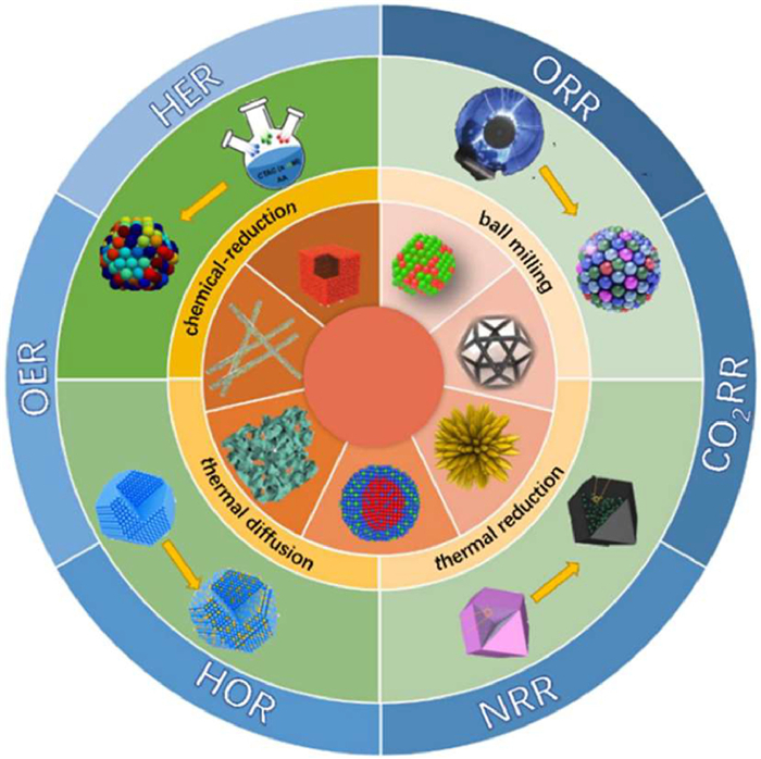
Figure 1.
Schematic diagram summary of synthesis methods, morphologies and applications of alloy electrocatalysts.
Alloy as advanced catalysts for electrocatalysis: From materials design to applications
Pingfan Zhang , Shihuan Hong , Ning Song , Zhonghui Han , Fei Ge , Gang Dai , Hongjun Dong , Chunmei Li

Energy consumption is growing rapidly due to population growth, industrialization and technological development. In addition to rising energy demand, fossil energy reserves are rapidly declining [1,2]. Fuel cells, water electrolyzers, metal air cells, and other energy technologies have begun to play some role in our renewable energy landscape [3-5]. Developing efficient, low-cost advanced electrocatalysts that can be used in large-scale electrochemical devices is crucial to achieving this vision and poses significant scientific challenges [6-9]. Electrocatalysis is a chemical effect in which modifiers (electroactive or non-electroactive) present on the electrode surface or in the solution phase can promote or inhibit the electron transfer reaction occurring in the electrical damage without changing the modifiers themselves on the electrode surface or in the solution [10-12].
Electrocatalyst is one of the key materials in electrocatalytic reaction, and its activity plays a key role in the rate and cost of electrocatalytic reaction. Pure metals have been extensively studied for electrocatalytic reactions, and noble metals such as platinum and ruthenium are the most active and stable materials, but their extremely high cost and limited reserves are the main obstacles to their industrial application [13-16]. Therefore, one of the most important goals of modern electrocatalysis is the complete replacement of pure noble-metals by low-cost and active catalytic materials [17,18]. Although non-platinum active metals such as Fe [19], Ni [20] or Co [21,22] are much cheaper, these metals are subject to corrosion and passivation under reaction conditions, their performance and durability limit the widespread adoption of such systems [23]. Compared with monometallic catalysts, multi-metallic alloy catalysts exhibit remarkable electrocatalytic performance due to optimized electronic structure, atomic system synthesis conformation and synergistic effects [24-27]. Alloying different metals can lead to increased intrinsic electrocatalytic activity [28], altered morphology (intrinsic specific surface area) [29] and high corrosion stability [30]. The combination of different metal elements in alloy nanomaterials can improve the stability of electrocatalysts, avoiding the problem of easy oxidation and deactivation of pure metal electrocatalysts in the reaction.
The progress of materials science and nanotechnology has greatly promoted the synthesis of alloy nanostructures and multiplied the application of electrocatalysis. Given the rapid developments in this field, there is a clear need to provide timely updates on the design of alloy nanomaterials for electrocatalytic applications. This review provides an overview of recently reported design strategies of alloy catalysts for electrocatalytic related energy technologies, and further outlines the underlying mechanisms behind the enhanced catalytic performance of alloy electrocatalysts, including composition regulation, morphological control, strain engineering, defect engineering, and interface engineering. Then, we summarize the application of these alloy catalysts as efficient catalysts for important electrochemical conversion reactions (oxygen reduction reaction (ORR), hydrogen precipitation reaction (HER), formic acid oxidation reaction (FAOR) and CO2 oxidation reaction (CO2RR), etc.) and offer a brief outlook on the future developments in this research field (Fig. 1).
Alloys are substances with metallic characteristics that are synthesized by fusing two or more metals with metals or nonmetals [31,32]. They are formed by the process by which one component enters the structure of the base component (metal or metal compound) [33]. Non-metallic elements, notably H, B, C, Si, and P, can be added to alloys to make interstitial alloys or intermetallic compounds [34]. In terms of composition, alloy systems may be classified and distinguished into three groups: noble metal, base metal, and noble/base metal mixed alloys. It is classified as binary alloys, ternary alloys, and multi-alloys based on the number of component elements, and alloys that include five or more metal elements in the multi-alloy are called high-entropy alloys [35-37].
According to different structures, alloys are mainly divided into three types (Fig. 2a): The first type is mechanical mixture alloys, which is a mechanical mixture of different metals with different melting points that crystallize to form fine crystals. The two components of the alloy cannot dissolve one another or interact to form compounds; each phase retains its original lattice and properties in the mechanical mixture.
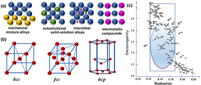
The second type is solid-solution alloys: a solid-solution that not only dissolves a variety of metals during melting, but also maintains a miscible state when solidifying is called solid-solution alloys. The solid-solution alloy is a uniform liquid phase in the liquid state, and the metal with more content in the alloy is called solvent metal, and the metal with less content is called solute metal. After the solid-solution is converted into a solid state, the uniformity of the structure is still maintained, the lattice type of the solvent metal is maintained. The solute metal can be limited or limited to column separation in the lattice of the solvent metal. According to the position of solute atoms in the solvent lattice, solidsolution alloys are further divided into substitutional solid-solution alloys, interstitial solid-solution alloys. Substitutional solid-solution alloys: the solute atoms of solid-solution are generally atoms with a small difference in radius. Interstitial solid-solution alloys: solute atoms in the solid-solution are non-metallic atoms (H, O, N, C, B) with small radius (Rsolute-atoms/Rsolvent-atoms ≤ 0.59). The solute atoms replace part of the solvent lattice to form substitutional solid-solution, and the following factors affect the solid-solution degree of the substitutional solid-solution: (1) The type of crystal structures (face-centered cubic (fcc, including Al, Cu, Ag, Au, Ni, Pb, γ-Fe), hexagonal close-packed (hcp, including Ti, Zr, Mg, Zn) or body-centered cubic (bcc, including α-Fe, W, Cr, Mo, V) crystal structure) of metal elements are the same, and it is possible to form an infinite solid-solution (Fig. 2b). Only when the structure of components A and B is the same, can they be completely miscible in any proportion. The value of x in AxB1-x can vary between 0 and 1. (2) The closer the atomic sizes of the elements, the more stable the solid solution formed. (3) The greater the difference in electronegativity between alloying elements, the greater the tendency to produce compounds that are not conducive to solid-solution formation (Fig. 2c) [38].
The third type of alloys is intermetallic compounds (IMCs). The structure of the solid-solution alloys is the same as the original solvent-metal, but the crystal structure or system of IMC as opposed to the solid solution alloy is different from the parent metal. IMCs have a different crystalline and atomic structure from the original metal and can form new ordered superlattice structures.
We systematically summarize several advanced and suitable characterization methods to understand the characteristics (including elements, morphology, structure, phase, surface chemical state, lattice distortion and strain) of alloy electrocatalysts.
In terms of elemental identification and quantification, inductively coupled plasma (ICP) emission spectroscopy is one of the most important techniques for accurately identifying the type and actual content of elements in alloy electrocatalysts. Through scanning electron microscopy (SEM) and transmission electron microscopy (TEM) and other technical means, the morphological characteristics, particle size, morphology and distribution uniformity of alloy electrocatalyst surfaces are observed and analyzed. High-angle annular dark field scanning transmission electron microscopy (HAADF-STEM), atomic force microscope (AFM), and scanning tunneling microscopy (STM) provide further insight into three-dimensional morphology and elemental composition. Xray diffraction (XRD) is the primary method for studying the physical phase and crystal structure of alloy electrocatalysts, allowing the analysis of material properties such as the composition of alloy molecules, crystal shape, intramolecular bonding patterns, and conformation. Synchrotron XRD has a higher structural resolution than conventional XRD. In addition, XRD can be used to assess the crystallinity, particle size, and lattice parameters of HEA by fitting diffraction data. X-ray diffraction (XRD), Raman spectra and X-ray absorption fine structure spectroscopy (EXAFS) and other technical means are used to explore the crystal structure and crystal face orientation of alloy electrocatalysts, and determine their crystal structure type, lattice constant, functional chemical composition and other element information. Metal-metal interactions are required for alloy formation and can lead to characteristic peak shifts. Electrocatalytic processes usually occur at the catalyst surface and at the electrolyte interface. The electronic structure, chemical bond characteristics, and ion state of alloy electrocatalysts are examined using scanning tunneling microscopy (STM) and X-ray photoelectron spectroscopy (XPS), which provide essential support for improving the catalytic performance of alloy electrocatalysts.
In order to obtain the ideal alloy electrocatalyst, it is necessary to master various synthesis methods. In this chapter, we mainly summarize some different synthesis methods of alloys and relevant representative examples. At present, the main methods for preparing alloys are co-reduction method, electrochemical-deposition method, pyrolysis reduction method, thermal diffusion method, seed-mediated method, mechanical ball milling method, etc.
The chemical reduction method is to reduce metal ions to metal atoms, and then prepare alloy electrocatalysts through self-assembly or other methods. The chemical reduction method for manufacturing alloy electrocatalysts has the advantage of being able to selectively vary the surface structure and composition of the catalyst by regulating the reduction conditions, allowing for the manipulation of catalytic activity and selectivity. In addition, alloy electrocatalysts synthesized by the reduction method have high stability and repeatability, which can effectively reduce issues such as catalyst deactivation and shortened lifespan.
Co-method: Multiple metal salt precursors and reducing agents in the system are simultaneously reduced to form alloy nanomaterials using the co-reduction method, which is also referred to as the simultaneous reduction method. Therefore, in addition to metal salt precursors, in the process of co-reduction synthesis of alloys, it is also necessary to add capping agents, reducing agents and surfactants to achieve co-reduction of different metal precursors in the solution system. In the co-reduction process, metal salt precursors mostly use chloride, perchlorate, nitrate, acetate and acetylacetonate. Strong reducing agents can simultaneously reduce all metal precursors and promote the formation of nanoalloys with different structures/morphologies. Co-reduction method often uses reducing agents such as ascorbic acid, citric acid, hydrogen peroxide, sodium borohydride, benzoic acid, cuprous chloride, polyols. Surfactants (cetyltrimethylammonium bromide (CTMAB), polyvinylpyrrolidone (PVP), octadecylamine (ODA), oleylamine (OAm), etc.) can modulate the crystal growth behavior by regulating the surface energy of the particles to create nanoalloys with unique structures or morphologies and prevent aggregation of nanoalloys. Commonly used end capping agents are halide ions, organic phosphine or organic amines and so on. As a representative study, Zhou et al. prepared mesoporous PdAg nanospheres of uniform size and composition by co-reducing H2PdCl4 and AgNO3 in aqueous solution using dioctadecyl dimethyl ammonium chloride (DOAC) as surfactant and ascorbic acid as reducing agent. DOAC is a double-chained quaternary ammonium surfactant that is known to form unilamellar vesicles under the given experimental condition. These vesicles directed the nucleation and growth of mesoporous PdAg nanospheres [39]. Shan et al. co-reduced the Ce(CH3COO)3/Cu(CH3COO)2 metal precursors in the presence of PVP to obtain the Ce–Cu alloy nanocrystals by using triethylene glycol (TEG) as the reductant [40]. And Su et al. used porous nitrogen doped carbon coated titanium dioxide (TCN) as a carrier to uniformly immobilize NiRu alloy on the surface of the carrier using an impregnation co-reduction method (Fig. 3a). The TCN was impregnated in Ni(NO3)2 and RuCl3 solution, and then Ru3+ and Ni2+ were adsorbed on the TCN surface due to its large specific surface area and surface-specific functional groups. Finally, Ru3+ and Ni2+ were rapidly co-reduced by a freshly prepared NaBH4 solution [41]. Li et al. first obtained PtPd mesoporous nanospheres (PtPd MNs) by co-reducing Pt and Pd precursors with L-ascorbic acid (AA) in the presence of surfactant F127, and then fabricated PtPdNiP-MNs by further introducing Ni and P components (Fig. 3b) [42].
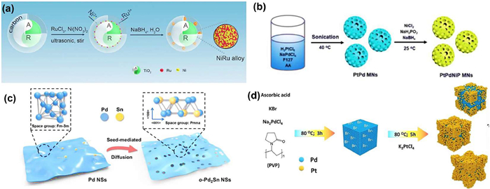
Seed-mediated method: Seed-mediated method is to obtain nanoparticles with different morphologies by first reducing the precursors of the first metal due to the difference in thermal decomposition ease or reduction potential, and use them as seeds for the next coating of the second metal precursor. The second metal is grown in the outer layer of the nucleus of the first metal by adding reducing agents, capping agents and inorganic ions to the precursor of the second metal. Seed-mediated growth is an appealing approach for the deliberate synthesis of core-shell structural alloys, enabling precise manipulation of shell thickness, core and shell composition, as well as nanocrystal morphology [43]. A seed-mediated co-reduction method developed by Bueno et al. involves simultaneous reduction of two (or more) metal precursors to deposit bimetallic (or polymetallic) shells onto seeds and random alloy (ra-) PtM surfaces onto ordered intermetallic compound (i-) PdCu seeds by seed-mediated co-reduction. These core-shell alloys exhibited higher specific and mass activity in ORR, the activity enhancement was attributed to the strain surface caused by lattice mismatch between the intermetallic nucleus and the random alloy surface, the excellent durability is attributed to the ordered structure of the intermetallic core [44]. Liang et al. successfully prepared ultrathin and defect rich intermetallic Pd2Sn nanosheets (NSs) through seed mediated methods (Fig. 3c). Pd NSs were first produced in oleylamine (OAm) at 160 ℃, followed by the controlled reduction of Sn4+ and diffusion of Sn atoms into Pd lattice at 170 ℃. The seed mediated method can better preserve the two-dimensional structure during the phase transition process of nanosheets, while the process of diffusion and migration of Pd/Sn atoms induces the formation of a large number of defect site [45]. Xiao et al. synthesized a Pd@Pt core-shell nanocube using a direct seed mediated growth approach that entails constantly introducing Pt shell forming chemicals into a solution containing nuclear nanoparticles without the requirement for washing throughout the synthesis process (Fig. 3d) [46].
Electrochemical-deposition method: Electrochemical deposition methods offer the advantages of simple setup, simple operation, and controlled synthetic composition. Electrochemical deposition refers to the reduction of different types of metal ions from aqueous/non aqueous solutions or molten salts while transferring electrons on the working electrode under the action of an external electric field, and then depositing them on the electrode to form an alloy structure. For instance, Nugraha et al. synthesized mesoporous AuCuNi ternary alloy films by electrochemical deposition (Fig. 4a). Specifically, the metal precursor solution containing HAuCl4, CuSO4 and NiCl2 were added dropwise to the copolymer solution under constant stirring, followed by electrochemical deposition to generate mesoporous AuCuNi ternary alloy films. Subsequently, the polymer was removed by a simple solvent extraction method to make the mesoporous membrane free of impurities. Since the difference between the standard reduction potentials of the metal precursors is large, various constant potential ranges were adopted to affect the reduction rate of metals. The composition of the mesoporous AuCuNi films can be easily adjusted by changing the precursor ratio in the initial electrolyte solution [47]. Liu et al. used bulk Pt instead of salt as Pt source for electrochemical deposition to maximize the utilization of Pt (Fig. 4b). First, WO3 nanosheet arrays (WO3@CF) were grown on Cu foam by solvothermal reaction using WCl6 and C2H5OH. Then, the Pt species dissolved by electrochemical "activation" were reduced on low-potential HER working electrodes to form hollow PtCu nanospheres (PtCu/WO3@CF) closely growing at the edge of WO3 nanosheets. The release of Pt species from bulk Pt to the electrolyte was a kinetically slow process with OER proceeding and thus the amount of loaded Pt can be well controlled [48]. Wang et al. obtained dendritic CuNi alloy catalyst by electrodepositing on a rotating disk electrode (RDE) and polytetrafluoroethylene (PTFE) film using a solution containing CuSO4+NiSO4 as a deposition bath [49].

Pyrolysis reduction method is used to synthesize alloys by pyrolysis of metal-organic compounds as precursors. Zhu et al. prepared FeCo alloy nanoparticles functionalized nitrogen-doped mesoporous carbon catalysts by a simple two-step synthesis method, including coordination induced self-assembly and high-temperature pyrolysis of multi-level bimetallic organic composite scaffolds (Fig. 4c). In the final high-temperature pyrolysis step, the binding ligands served as the nitrogen and carbon source while the metal ions (Fe2+ and Co2+) served as metal precursors, resulting in the formation of the dual metal-containing nitrogen-doped carbon framework. Simultaneously, under the assistance of redox conditions generated during pyrolysis, metal ions could be reduced to FeCo NPs. The electronic structure of the active site of Co was regulated by Fe atom, which makes the binding energy of the catalyst to the intermediate of oxygen reduction reaction reach the best [50]. Zhang et al. prepared a novel hybrid consisting of RuCo alloy bimodal nanoparticles embedded in N-doped carbon through a simple package pyrolysis strategy (RuCo@NC-600) (Fig. 4d). First, a columnar layered chiral metal-organic framework (cMOF-CoRu) containing Co and Ru ions was synthesized by a pot of solvothermal reaction, and then the MOF precursors were pyrolyzed in flowing Ar at different high temperatures to obtain RuCo@NC-600 [51]. Without expensive additives or prefabricated seeds, Jenkinson et al. prepared faceted FePt-Fe3O4 dumbbell-shaped nanoparticles by reducing Pt(acac)2 in oleic acid, oleamine and octadecene and adding Fe(CO)5 at 120 ℃ for thermal decomposition. Through temperature control, it is possible to selectively manipulate the morphology of the FePt lobe while maintaining a desirable Fe50Pt50 composition [52].
When heated at high temperatures, the thermal movement of the crystal atoms of the metal intensifies, and when the atoms gain enough energy, they leave the lattice position and migrate to the lattice or vacancy of other metals to create alloys. Yang and other researchers synthesized a Pt-based i-NP library i-NPs library composed of 46 Pt and 16 other metal elements. Ordered intermetallic compounds are thermodynamic stable relative to disordered solid solutions, but the kinetic energy barrier of atomic ordering must be overcome to realize the transition from disordered to ordered. After high-temperature annealing at 1000 ℃, the precursors formed the atomically ordered Pt3Co intermetallic structure after cooling below the phase-transition temperature through the thermodynamic-driven disorder-order transition (Fig. 5a) [53]. Zhao et al. successfully constructed a double atomic-tuned RuBi SAA/Bi@OG nanostructure composed of RuBi single-atom alloy nanoparticle with Bi-O single-site-doped graphene by high-temperature diffusion (Fig. 5b). During the heating process at 900 ℃, the precursor powder may first form an alloying RuBi intermediate, and then due to the significant difference in melting and boiling points between Bi and Ru, the Bi metal was atomized to form multi-level Bi single atoms [54]. Guo et al. synthesized Pd3Pb multiple twinned intermetallic nanowire networks (MT-IM-NNs) through the diffusion and ordering process of Pb atoms in the preformed Pd seeds into Pd3Pb intermetallic phases and the directional attachment of seeds. The diameter of Pd3Pb MT-IM-NNs can be adjusted by changing the crystal size and type of Pd cubic seeds. Interestingly, when the palladium icosahedron was used as the seed, the Pd3Pb multiple twin metal porous nanowire network was obtained [55].
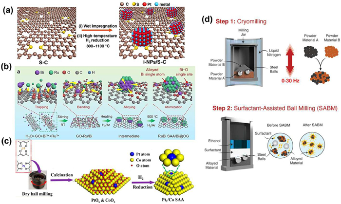
Mechanical ball milling can grind the sample material to nanometer size while changing the reactivity of the ground solid, activating chemical reactions, and inducing phase transitions (amorphization, polymorphic conversion) [3]. Mechanical ball milling to prepare alloying materials is a physical synthesis method for alloying two metals with significantly different melting points to overcome the limitation of stoichiometric composition of phase diagrams [56,57]. Because of the advantages of low cost and easily scalable and environmentally friendly properties, the ball milling process has aroused increasing interest. Gan et al. successfully achieved the kilogram scale preparation of the atomic dispersion of Pt within Co nanocrystals (denoted as Pt1/Co) using two acetylacetone salts with properties very close to each other, through ball milling, high temperature calcination, and hydrogen reduction (Fig. 5c). This method is simple, efficient, solvent-free, and has no size amplification effects, is easy to achieve kilogram scale preparation [58]. Abed et al. synthesized nanocrystalline Ni–Co–Se at low temperatures using ball milling technology, the combination of high-speed mixing (30 Hz, 1800 rpm) and low temperature (-196 ℃) promoted the formation of nanocrystalline structures centered on high melting point components (Fig. 5d) [59].
The methods described above are a few that are often utilized to create nanoalloy catalysts. differing synthesis techniques can result in differing catalyst performance; thus, while choosing an appropriate synthesis method, it is critical to consider the catalyst composition and control parameters during the preparation process to get the optimal performance. Nanoalloys can also be produced using other techniques including sol-gel method [60], microwave synthesis method [61], magnetron sputtering method [62], dealloying method [63], etc. To obtain the best performance, it is necessary to thoroughly consider the catalyst components and control factors during the preparation process.
Through recent synthesis experiments and theoretical research, researchers aim to reasonably optimize the design of alloy nano-particle electrocatalysts. By judiciously adjusting and controlling the composition, size, structure, morphology, sequence and dispersion of the catalysts, the catalysts have higher catalytic performance and improved the atomic utilization efficiency
Alloying is the change of electrocatalytic properties (selectivity, reaction rate, etc.) by modulating the d-band holes of the metal catalyst, including changing the electronic properties, reduction, and dispersion of the metal catalyst. Controlling the type of metal combined and the proportion of each component can reasonably and effectively optimize the comprehensive properties of the alloy, which is one of the directions that need further research in the future.
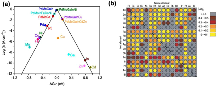
Further, in the synthesis of alloyed nano-electrocatalysts, precise modulation of the intermediate binding energy of the catalyst by adjusting the component metals is an important way to design high-performance electrocatalysts. According to Sabatier's principle, if the interaction between the catalytic active site and the reactant molecule (H*, OH*, OOH*, O*, N2H*, OCHO*, etc.) is weak, the adsorption of the reactant molecule is not favorable; if the bonding between the catalytic active site and the reactant molecule is too strong, the desorption of the reactant molecule is not favorable. Therefore, the electrocatalytic activity can be optimized only when the interaction between the catalytic active site and the reactant molecules is moderate. As a typical study, Fu et al. synthesized PdMoGaInNi high entropy alloy nanosheets through theoretical calculation and screening, and showed high HER activity in acidic medium. According to the Sabatier principle, if the bond cooperation between the catalytic active site and H is weak, it is not conducive to the adsorption and conversion of H*. If the bond cooperation between the catalytic active site and H* is too strong, it is not conducive to the desorption of H*. Only if the bond cooperation between the catalytic active site and H* is moderate, can the optimal HER catalytic activity be displayed. In the volcanic map (Fig. 6a), the HER activity corresponds to the hydrogen binding energy (HBE) of the catalyst. The flexible adjustment of the components in the alloy and the synergistic effect between the components of the metal can help to adjust the electronic structure of the active metal, thus realizing the fine control of HBE. For the consideration of strong and weak balance, the metal components of strong HBE and weak HBE are combined and tuned to achieve the optimal HBE of the alloy system. Finally, PdMoGaInNi high entropy alloy was the closest to the volcanic peak and was considered as the best combination [64]. Professor Jens K. Nørskov from the Technical University of Denmark also gave some high-throughput calculations for researchers to screen and predict HER catalysts and their performance in advance. Nørskov from the Technical University of Denmark also gave some high-throughput calculations for researchers to screen and predict HER catalysts and their performance in advance. The plot clearly shows that many binary surface alloys have high predictive activity for HER. The plot clearly shows that many binary surface alloys have high predictive activity for HER (Fig. 6b) [65].
The morphology of the alloy controls the surface exposed during the electrocatalytic process to a certain extent. The different exposed surfaces will affect the adsorption performance of reactants, intermediates and products, thereby changing the overall electrocatalytic performance [66]. Considering the rapid development of alloyed electrocatalysts, it is necessary to review and summarize how the nanoalloy morphology and structure affect the electrocatalytic activity, stability, and selectivity.
Nanoparticles are one of the most common morphological structures in alloys. The physical and chemical properties of alloy particles can be modulated by changing the particle composition, atomic ordering, and size. Reducing the size of metal nanoparticles can improve the catalytic performance of catalysts. In general, the smaller the particle size, the greater the percentage of surface atoms, exposing more nanoalloy surface area and accelerating the active site of electrocatalytic catalysis.
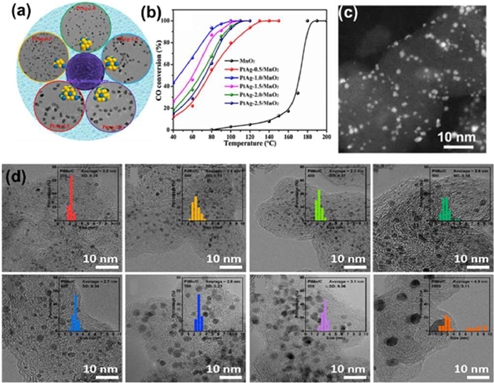
The smaller the diameter of the nanoparticles, there will be more corners and edges, a relatively high density of low coordination sites may enhance the interaction between catalyst and intermediate molecules in the electrolyte solution, thereby increasing the efficiency of the electrocatalytic reaction [67,68]. A simple ethylene glycol reduction pathway was successfully used by Mo et al. to synthesize bimetallic PtAg alloys with uniform size and element distribution, and the reduction time was used to adjust the particle size (ranging from 3.3 nm to 5.8 nm) (Figs. 7a and b). Then, PtAg alloy was fixed on MnO2 microspheres to generate a new PtAg alloy/MnO2 catalyst. The size of PtAg alloy particles significantly affected their catalytic activity and stability for CO oxidation, and maintained the highest specific CO oxidation catalytic activity at relatively small particle sizes [69]. Minamihara et al. successfully synthesized ultrasmall 1.32 ± 0.41 nm tiny IrPdPtRhRu high entropy alloy nanoparticles using an originally developed continuous-flow reactor and a strong reducing agent (Fig. 7c). Increasing the ratio of surface to volume (which usually contributed to the catalytic activity) was important for the effective use of precious chemical elements. Five elements were evenly distributed in the ultrafine nanoparticles with fcc structure and had significant high activity for HER [70]. Yoon et al. prepared ORR electrocatalysts of Pt-Mo solid solution alloys (PtMo/C) on carbon support on a large-scale basis by a one-step gas phase synthesis method without using any organic additives or reducing gases (Fig. 7d). The particle size of PtMo alloys was optimized by controlling the temperature of the synthesis conditions. The particle size of PtMo/C (PtMo/C-800) annealed at 800 ℃ was optimized to about 3.1 nm and showed the highest specific activity, superior to commercial Pt/C and exhibiting excellent durability after accelerated degradation testing [71].
Nanosheets can improve the atomic use efficiency of metals, which is attributed to their large surface-to-volume ratio and high-density unsaturated atomic catalysis. The smaller the nanoplate the higher was the percentage of the atoms at the edges, which resulted in the increased activity toward ORR [72]. Kwon et al. successfully synthesized MoSe2–VSe2–NbSe2 (denoted as (MoVNb)Se2) ternary nanosheets via a hot-injection colloidal reaction at 340 ℃ (Fig. 8a), which showed a large surface area-to-volume ratio, allowing more H adsorption sites to favor HER [73]. Li et al. synthesized a kind of tri-metallic palladium-silver-copper nano-sheet assembly (PdAgCu NSAs) by hydrothermal method. Compared with single-metal Pd and bimetallic PdAg NSAs (Fig. 8b), the prepared tri-metal alloy structure provided many active sites, resulting in large electrochemical active surface areas (ECSAs) and significantly enhanced catalytic performance of C2 alcohol electrooxidation with excellent long-term stability [74]. Wang et al. synthesized a series of ultra-thin two-dimensional Ru-M (M = Co, Ni and Cu) nanosheets by simple one-pot solvothermal method, achieving faster CO2RR and carbon dioxide evolution reaction (CO2ER) kinetics due to quantum size effects, ultra-large surface volume ratios, abundant surface low-coordination atoms and abundant in-plane RuCo alloy sites in two-dimensional nanostructures (Fig. 8c) [75].

Nanowires with a length-to-diameter ratio greater than 100 are collectively called nanowires, and those with a length-to-diameter ratio of less than 100 are called nanorods. Twisted (or wavy) nanowire (NW) catalyst nanostructures, which form multiple anchor points on the electrode surface and significantly inhibit the separation and agglomeration process, and obtain additional stability from self-entanglement. Sahoo et al. reasonably designed PdNi twisted nanowires, use the co-reduction of H2PdCl4 and NiCl2 in the presence of PVP to generate ultra-thin PdNi-TNW (Figs. 8d and e). A small change in HCl concentration will also lead to a large deviation from the required twisted morphology. TNW morphology provided (ⅰ) more grain boundaries than nanoparticles, (ⅱ) more active sites due to kinks, surface roughness, and the presence of edge atoms, and (ⅲ) Ni doping into the internal Pd lattice produced ideal surface strain and a more positive Pd surface [76]. A facile particle attachment mechanism synthesized by a solvothermal process for Pt3Ag alloy wavy nanowires was investigated by Fu et al. TEM and EDS showed that the Pt3Ag alloy had a highly wavy nanowire structure with an average diameter of 4.6 ± 1.0 nm and a uniform elemental distribution. Due to the partial electrons transferred from Ag to Pt in Pt3Ag alloys, which weakened CO binding and CO poisoning. And the one-dimensional nanowire morphology also contributed to favorable charge transport properties, the resulting alloy nanowires can be used as efficient electrocatalysts for ethanol oxidation reactions (EOR) [77]. Zhou et al. synthesized Pd3Sn nanorods with the comparable size and morphology but different crystal phases by a wet-chemical approach (Fig. 8f). The crystal phase of as-prepared nanorods could be easily tuned from the ordered intermetallic (L1 phase) to disordered alloy (fcc phase) by simply altering the types of tin precursors and solvents [78].
Alloy polyhedral structures are mostly cubic, octahedral, dodecahedral, icosahedral, etc. Han et al. prepared Cu2O nanocubes in advance and synthesized the porous trimetallic PtRhCu cubic nanoboxes (CNBs) by the galvanic reaction between K2PtCl4, RhCl3, and Cu2O nanocubes template (Fig. 9a). PtRhCu CNBs were easily prepared by the current reduction between K2PtCl4, RhCl3 and Cu2O nanocubes templates. The introduction of Rh effectively enhanced the ability of the catalyst to cleave C-C bonds, and the introduction of Cu introduction enhanced the catalytic oxidation performance of CO intermediates. The porous nanobox-like structure meant that the utilization of noble metals can be greatly improved because of the good mass transfer and the full utilization of the inner surface. Based on the unique structural effect of material and the synergistic effect between the three metals, PtRhCu-CNBs showed excellent electrocatalytic performance for catalytic EOR [79]. Liu et al. employed the interfacial reduction of active hydrogen (H*) to convert Pd {100} nanocubes into octahedral crystalline species surrounded by low-surface-energy {111} facets (Fig. 9b), making it convenient to fabricate {111}-faceted Pt–M alloy nanoshells that are particularly desirable for the HER. The introduction of HNO2 into the reaction generates H* at the metal seed/solution interface, creating a highly reducing environment. HNO2 is introduced into the synthesis to establish an oxidative solution phase and a reductive palladium seed/solution interface. This unique microenvironment enables Pd {100} nanocubes to be used as seeds in the synthesis. The {111} facets and the customizable Pt/Ni ratio in the alloy nanoshells made it possible to achieve substantially decreased hydrogen binding energy (ΔGH*) due to the combined ligand and facet effects, octahedral Pd@Pt–M alloy nanocrystals to showed superior electrocatalytic performance in the HER [80]. Tang et al. synthesized ternary Pt-Ni-Cu highly excavated rhombic dodecahedrons (Pt-Ni-Cu ERDs) in one step by stirring-assisted solvothermal method. The nanocrystals were highly uniform and monodispersed and had a well-defined 3D accessible excavated rhombic dodecahedral structure with an average edge length of 15.7 ± 1.3 nm, which increased the specific surface area and therefore the contact between the catalysts and reaction species (Fig. 9c). More importantly, a large number of stepped atoms were observed on the surface of this structure, which would increase the exposure of active sites and thus improve the electrocatalytic performance of methanol oxidation [81]. Xu et al. synthesized Au60Pd40 icosahedron with an average size of 30.6–32.6 nm after heating HAuCl4, Pd(acac)2, KI and PVP at 150 ℃, significantly enhanced activity and durability for ORR in acidic environments [82].
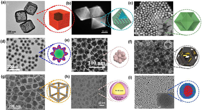
3D nanoflower structures typically exhibit better adsorption and electrocatalytic properties because the inhomogeneous distribution of elements produces a unique local coordination environment. Such structures readily expose small planes of high refractive index at the edges, which can provide abundant active sites for the electrocatalysts and improve their catalytic activity. Liu et al. used Pt(acac)2, Fe(acac)3 and Rh(acac)3 as metal precursors, glucose as reducing agent, celyltrimethylammonium chloride (CTAC) as surfactant and oleylamine (OAm) as solvent to synthesize FePtRh nanoflowers with a diameter of 30 ± 10 nm by a simple one-pot wet chemistry method. The unique core/shell nanoflower structure of FePtRh facilitated the reduction of CO* adsorption energy and exhibited excellent activity and stability towards MOR and EOR [83]. Lai et al. used seed-mediated growth techniques to selectively grow Ag and Pd on Au nuclei to generate highly branched and dispersed AgPd alloy shells, synthesizing Au@AgPd trimetallic nanoflowers (Au@AgPd NFs) (Fig. 9d). The ratio of Ag to Pd, sizes of Au core, and surfactant cetyltrimethylammonium bromide together contributed to Au@AgPd NFs, which had a unique structure, exhibited the traits of tiny size, many flaws, and extensively distributed alloy shells [43]. Qiao et al. prepared PtCuRu nanoflowers (PtCuRu NFs) by hydrothermal co-reduction using dimethyloctadecylammonium chloride (DDAC), Pt(acac)2, Cu(acac)2 and RuCl3, C6H8N2 and OAm (Fig. 9e). The best Pt0.68Cu0.18Ru0.14 NFs with high alloying, Ru-rich edges and abundant high index surfaces exhibited outstanding electrocatalytic performance for MOR and EOR [84].
As a kind of hollow structure, nanoframes have a highly open three-dimensional space structure, a large specific surface area and high density of catalytic active sites. Nanoframes alloys are also not easy to agglomerate in catalytic reactions. Two synthesis strategies for nanoframes alloys: (1) First selectively deposit one metal on another metal template, and then selectively etch out the metal template; (2) The metal nanocrystals with hollow or solid structure are dealloyed by substitution reactions or oxidative etching to obtain the nanoframes structure. Haddadnezhad et al. selectively deposited Pt on the edge and terrace of Au NPs by fine-tuning the chemical potential of solution, followed by inner Au etching and eventually leading to all-open Pt NFs or half-open Pt walled nanoframes. Then obtained the Pt double-walled nanoframes (DWFs) by electro-displacement reaction between Ag and Pt (Fig. 9f). This synthesis resulted in the internal Au being etched to maximize the internal specific surface area and catalytic active site, further enhancing the MOR performance [85]. Xiong et al. first produced single-crystal Ag nanocubes, and then added cetyltrimethylammonium chloride as a structural inducer (and ascorbic acid as a reducing agent) with chloroauric acid to yield the desired cubic Ag3Au nanoframes (Ag3Au NFs) (Fig. 9g). The alloy atomic configuration and abundant structural defects of Ag3Au NFs greatly contributed to CO2 activation in thermodynamics and kinetics, thus significantly reducing the required overpotential and increasing the current density conversion of CO2 [86].
Core-shell alloy electrocatalysts have special lattice strain and ligand effects to optimize geometric and electronic properties. Typical methods for forming core-shell/alloy structures include seed-mediated growth, thermochemical calcination, adsorbent-induced evolution, chemical dealloying, underpotential deposition/current displacement. Lyu et al. first prepared nano-Pt-Ni alloy particles with gradient distribution from surface to interior by galvanic displacement reaction on graphene substrate, and then prepared Pt-Ni alloy core-shell nanoparticles (Pt-Ni@PtD/G) with defective Pt surface by partial dealloying to remove Ni (Fig. 9h). Due to the lack of nickel on the surface, more Pt active sites were exposed on the surface of the catalyst. And the change of Pt-Pt bond length generated by nickel vacancies caused compression strain on the Pt surface, so the Pt-Ni@PtD/G catalyst showed good ORR catalytic performance in acidic electrolyte [87]. Liu et al. first synthesized CuNi alloy seeds and then reacted with the electric displacement of Pd2+ precursors at high temperatures in organic media to convert CuNi alloy seeds into CuPd alloy particles coated with NiPd alloy shells (Fig. 9i). In these unique core−shell nanostructures, the compressive lattice strain between core and shell regions and the electronic interaction between Pd and transitional elements could be coupled together to lead to a downshift of the d-band center of Pd sites, thus endowing them with good activity for catalyzing EOR and ORR [88]. Wang et al. used oleamine as solvent and reducing agent at low temperature, Au with high oxidation-reduction potential was reduced before Ir to form a core. With the increase of temperature, Ir atoms were deposited on the surface of Au by atomic diffusion, forming the surface of Au-Ir alloy Au@AuIr2 core-shell nanoparticles. The electronic interaction between Au and Ir leaded to the formation of partially oxidized surface, providing a balance for the combination of different intermediates and achieving significantly enhanced OER activity [89].
This section summarizes that different morphologies and structures of alloys have different optimization effects on the local geometry/electronic structure of the alloy, which in turn has an important impact on the electrocatalytic performance. Precise morphology control of nanostructured alloys is essential to achieve their optimal catalytic activity and to achieve operational stability. The morphology of alloy catalysts essentially controls the type and abundance of surface crystalline facets exposed during electrocatalysis, with each different facet providing different interaction strengths with intermediates and different electrochemical stability during the catalytic reaction.
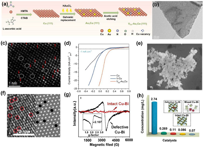
The introduction of defects in alloys is an effective strategy to improve the surface properties of nanocatalysts. Not only can the electronic structure of the metal particles be adjusted through atomic and charge rearrangement thus regulating the adsorption of intermediate substances, defects can also directly participate in the reaction and increase the number of active sites [90-92]. In recent years, rational control of the type or location of defects through appropriate strategies has become an effective strategy to modulate the electronic structure and adsorption behavior of electrocatalysts and improve the electrocatalytic performance and stability [93,94]. Common ways to create defects include dealloying, quenching, doping, etc. Zhang et al. combined single-atom alloy catalysts with metal atom vacancies to design metal catalyst surfaces at the atomic scale to improve the electrocatalytic NO3− reduction to NH3 reaction (NITRR) performance. Firstly, single crystal Cu(111)NSs were prepared by chemical reduction, followed by Au electro-displacement to prepare Au1Cu SAAs, and finally some Cu2+ leaching was made by acetic acid etching to form Cu vacancies (VCu-Au1Cu SAAs) (Figs. 10a–c). The isolated Au atom and adjacent Cu vacancies synergistically regulated the local electronic structure and geometry of the catalytic surface, thereby optimizing the energetics of intermediate bonding. They further used experimental and theoretical analysis to show that the SAAs structure of VCu-Au1Cu SAAs promoted the activation of H2O to *H, accelerated the NO3− hydrogenation kinetics, and promoted the desorption of *NH3, thereby significantly improving the intrinsic activity (Fig. 10d) [95]. Wu et al. first added DMSO and NH3·H2O to the C12H22BiN3O14 and CuCl2 mixture, and then quickly injected NaBH4 solution into the mixing system to synthesize the defective Cu-Bi alloy (Figs. 10e and f). Compared to intact Cu-Bi prepared by electrodeposition method, the higher signal intensity of EPR spectra and g-factor reflects the higher concentration of unsaturated Bi sites with unpaired electrons in the defective Cu-Bi alloy (Fig. 10g). The experimental results also showed that the defective Cu-Bi catalyst had important advantages in coupling carbon and nitrogen intermediates compared with the complete Cu-Bi alloy, so it was helpful to couple N2 and CO2 in the synthesis of urea in electrocatalytic aqueous solution (Fig. 10h) [91].
Since catalysis is a reaction that occurs on the catalyst surface, which changes the surface state of the catalyst and thus greatly affects the interaction between the catalyst and the reactants/intermediates, surface engineering can improve the selectivity and stability of catalysts through electronic and steric hindrance effects [96-98]. In general, the surface modification of nanoalloys can be broadly classified as follows: (1) Using surfactants to cover the surface of nanoalloys to impart new properties to the particle surface [99]; (2) Using mechanical stresses such as extrusion and friction to activate the nanoalloy surface and change the surface crystal structure and physicochemical structure [100]; (3) Coating the surface of the nanoalloy with a uniform layer of other substances to change the surface properties of the particle [101]; (4) Using chemical reactions to graft polymers with different functional groups on the surface of nanoalloys to give them new functions [102]; (5) Using organic or inorganic substances to precipitate a coating on the surface of nanoalloys to change their surface properties [103]; (6) Modification of nanoalloy sub-surfaces using high-energy corona discharge, ultraviolet light, plasma rays, etc. [104-106].
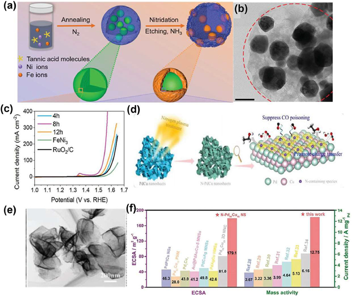
Chen et al. synthesized carbon coated surface engineering iron nickel nitride/alloy nanospheres (FeNi3-N) at different times and temperatures in an NH3 atmosphere (Fig. 11a). The biphase nitride on the surface increases the active center, regulates the electronic structure, and reduces the charge transfer barrier. In addition, due to the etching effect of NH3, more wrinkles and pores are formed after nitriding, which should be beneficial for mass and charge transfer (Figs. 11b and c) [103]. Meng et al. obtained a surface nitride nanosheet catalyst (N-Pd60Cu40 NS) prepared by N2 plasma treatment. Fig. 11d reveal that the as-prepared N-Pd60Cu40 NS are assembled with interconnected nanosheets, and the nanosheets are highly curved, forming obvious hierarchical structure. After electrocatalytic EOR performance test, compared with ordinary PdCu nanosheets, N-Pd60Cu40 NS had better catalytic activity in EOR because surface nitriding promoted charge transfer and inhibited CO poisoning, the stable Pd-N bonds generated after surface nitriding enhanced the stability of alloy nanosheets (Figs. 11e and f) [105].
Alloy strain engineering is considered to be a promising method for improving catalytic activity by changing the distance between atoms on the surface of particles or local regions, causing the size difference between the main atom and the doped atom, thereby generating local lattice strain and affecting the electronic structure [107]. Generally, compressive strain occurs when one metal is alloyed with another metal with a smaller atomic number/size [108]. Tensile strain occurs when one metal forms an alloy with another metal with a larger atomic number/size [109]. The strain effect causes the center of the d-band to move and changes the binding energy of the adsorbate, which can be applied to modified electrocatalysts [110,111].
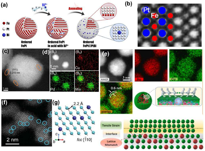
Guan et al. prepared a series of nanostructured Pt alloys by coating the alloy PtBi shell (Fig. 12a), the solid-solution FePt alloy was converted to chemically ordered Pt-alloy nanoparticles (intermetallic compound L10-FePt) by annealing, and then leached-embedding-rearranged to make L10-FePt coated by the alloy PtBi shell to obtain FePt@PtBi electrocatalyst. HAADF-STEM view of the L10-FePt core (Fig. 12b) showed regularly positioned bright and weak dots which correspond to the Pt and Fe atoms, respectively. EXAFS measurements and molecular dynamics (MD) simulations were used to investigate the origin of enhanced activity and stability of FePt@PtBi electrocatalysts—in-plane shear due to large Bi atoms in the Pt overlay produces surface compression with shortened Pt-Pt bonds, reducing the binding energy of the sorbent on the densely packed surface, resulting in more active Pt surfaces, thereby improving ORR performance [34]. Liu et al. used a gentle strategy based on acetic acid leaching for dealloying CuPd alloy nanoparticles. The shrinkage of the lattice constant was caused by the leaching of copper atoms in the outer layer of CuPd alloy nanoparticles to form vacancies, some vacancies can be identified in Figs. 12c and d. The higher activity of dealloyed CuPd nanoparticles might be due to the lattice compression in Pd-enriched surface layers and the exposure of more active Pd atoms [108]. Building core-shell metal nanostructures is one of the feasible methods to adjust surface strain. For example, Wang et al. applied a controllable ultra-thin copper sheet CuAu alloy (CuAu@2LCS) by solvothermal method (Fig. 12e), and the thickness of the ultra-thin copper sheet can be easily changed by simply adjusting the amounts of reactants, thus further adjusting the surface strain. Density flooding theory (DFT) calculations showed that the tensile strain optimized the electronic structure and surface properties due to the unique structure of the thin copper sheet bimetallic alloy, resulting in improved N2 chemisorption strength and enhanced NRR performance [112]. Zhang et al. introduced tensile strain into the Ru lattice by incorporating a low concentration of Pt atoms to enhance NRR performance (Figs. 12f and g, marked with circles caused expansion of intrinsic Ru lattice). The Ru88Pt12 nanowires were synthesized via a hydrothermal method. Theoretical calculations showed that lattice expansion caused by the introduction of larger atoms shifts upward in the presence of platinum atoms, enhancing the adsorption of N2 and selective stability of *N2H [113].
For specific chemical reactions, due to different electrocatalytic activity centers and different electrocatalytic mechanisms, different nanoalloy electrocatalytic materials should be selected and designed according to the mechanism of action of different reactions. In addition, due to the different conditions of the electrocatalytic reaction, the existence state and form of nanoalloy materials in the reaction process are also different, so the changes of the catalyst itself must be considered to reveal the electrocatalytic mechanism of different reactions. We summarize the recent progress in alloy nanomaterials as electrocatalysts in various electrochemical reactions.
Hydrogen has a calorific value 3-4 times higher than that of fossil fuels of the same mass, making it the most advantageous energy carrier [114-117]. Electrochemical water splitting is a promising technology for the production of high purity hydrogen under mild conditions, and the HER plays a crucial role in the process of hydrogen production from water as a semi-process in the process of water splitting [54,118]. As shown in Fig. 13a, the HER process is divided into two basic steps: (1) Adsorbing protons by absorbing electrons and (2) recombining protons into H2 molecules [119]. HER is a classical two-electron transport reaction and may occur via the Volmer-Heyrovsky or Volmer-Tafel mechanism. Too weak a chemisorption between H* and the catalyst limits the Volmer pace, while too strong an action inhibits the desorption of the Heyrovsky or Tafel steps. The HER performance of some recently reported alloy electrocatalysts is summarized in Table S1 (Supporting information).

Pt-based materials are the great HER catalysts, and Pt/C is commonly used as the HER benchmark. The use of alloys reduces the load of precious metals, reducing the cost of catalysts and improving the chances of HER activity. Guo et al. designed and synthesized an alloy nanostructure (Rh@Pt2L) with a Rh core and several Pt atomic layers. The overpotential of Rh@Pt2L was only 5 mV in 1.0 mol/L KOH (Fig. 13b) and 19 mV in 1.0 mol/L phosphate buffer solution (PBS, pH 7) (Fig. 13c) at a current density of 10 mA/cm2. In addition, in order to determine the HER catalytic mechanism of Rh@Pt2L, DFT calculations were performed on the adsorption energy of water and Gibbs free energy (ΔGH*), which confirmed that the excellent HER activity of Rh@Pt2L electrocatalyst in non-acidic media was attributed to the enhancement of hydrogen desorption and the reduction of the energy barrier during hydrogen generation (Figs. 13d and e) [120]. He et al. designed and synthesized FeCoNiWMo high-entropy alloys with a diamond-shaped structure and random atomic occupation (Fig. 13f). In HER, the catalyst has an overpotential of only 35 and 81 mV at a current density of 10 mA/cm2 at alkaline and acidic conditions (Figs. 13g and h), and the catalyst has excellent stability over 48 h. TEM revealed the selective substitution of metal atoms in the trapezoid structure, which formed a self-cyclic junction that enabled self-cyclic transport within the structure. DFT calculations revealed in detail that hydrogen was firmly adsorbed at the Co and Ni sites, while it can flow at the Mo and W sites (Fig. 13i). It is showed that the excellent catalytic performance of FeCoNiWMo HEA NPs catalyst mainly came from the self-circulation "ecosystem" structure composed of selective replacement of metal atoms and appropriate surface chemisorption energy, which made it easy for protons to cross the potential barrier and realize self-circulation transport within the structure [121].
HER and HOR are a pair of inverse reactions, which participate in the acquisition and conversion of hydrogen energy respectively. HOR and HER have similar reaction types and mechanisms [122,123]. In HOR, it usually starts from Tafel step and then goes to Volmer or Heyrovsky. HOR is a two-electron transfer reaction. Its intermediate contains various types of hydrogen, which depends on the pH value of the electrolyte. Hydrogen binding energy (HBE) and OH binding energy (OHBE) are generally considered as a key parameter to evaluate the kinetics of HOR. HOR occurs at the anode of proton exchange membrane fuel cell (PEMFC), but the acidic environment largely limits the catalytic materials used in the stable operation of PEMFC, which can be overcome by switching the operating environment from acidic to alkaline [98,124,125]. However, the kinetics of HOR in alkaline medium becomes quite slow, at least c of magnitude lower [126]. The HER performance of some recently reported alloy electrocatalysts is summarized in Table S2 (Supporting information).
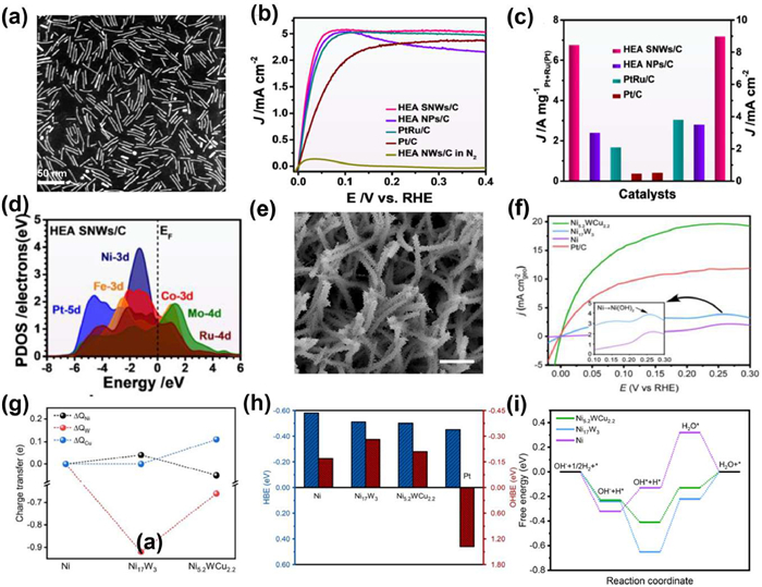
Alloy has been widely used in HOR in recent years, Pt/Ru-based alloys have made great progress in HOR, but Pt/Ru-based catalysts still have the disadvantages of high cost, poor stability and low resistance to CO poisoning. Zhan et al. fabricated PtRuNiCoFeMo HEA subnanometer nanowires (SNW) (Fig. 14a) with mass activity and specific activity as high as 6.75 A mg mgPt+Ru−1 and 8.96 mA/cm2, which were 2.8/2.6, 4.1/2.4 and 19.8/18.7 times higher than HEA NPs/C and commercial PtRu/C and Pt/C (Figs. 14b and c). In addition, even in the presence of 1000 ppm CO, the HEA SNWs/C catalyst exhibited excellent resistance to CO poisoning during HOR. DFT calculations showed that the strong synergy significantly changed the electronic properties of different elements in HEA SNW, Co and Ni sites maintained the highly stable valence states due to the pinning effect by nearby Fe and Mo sites, and the Pt and Ru sites modulated the overall electroactivity to further modulated the HBE and OHBE (Fig. 14d), thereby increasing HOR activity [127]. Nickel (Ni)-based compounds to replace expensive platinum (Pt)-based catalysts are currently one of the most promising materials as catalysts for driving HOR in alkaline environments. However, due to the formation of surface hydroxides, many of these nickel-based HOR catalysts are rapidly inactivated at temperatures above 0.1 V relative to the reversible hydrogen electrode (RHE). Qin et al. synthesized a ternary nickel-tungsten-copper alloy (Ni5.2WCu2.2) (Fig. 14e). Ni5.2WCu2.2 catalyst achieves higher HOR activity than a commercial Pt/C, with an anode potential of up to 0.3 V and good operational stability within 20 h (Fig. 14f). The reasons for the improved performance of the sample are further explored, XPS and Bader analysis indicated that electron donation from Ni to W once Cu participate in the alloy, leading to modulated electronic structure (Fig. 14g). DFT calculations showed that Ni5.2WCu2.2 gave rise an HBE close to Pt(111) and a stronger OHBE than Pt(111), which in turn promoted HOR kinetics (Fig. 14h). The free energy plot calculated by the reaction path of various catalysts showed that the much lower energy barrier obtained on Ni5.2WCu2.2 contributed to its excellent HOR performance (Fig. 14i) [128]. The geometric exchange current density of MoNi4 alloy synthesized by Duan et al. was 3.41 mA/cm2 towards the HOR, which is 1.4 times higher than that of commodity Pt/C catalysts. In addition, this alloy catalyst also showed impressive resistance to surface poisoning of the impurity CO in hydrogen fuel. And after 20 h of operation, HOR activity did not decrease significantly. The high reactivity was obtained by the optimized Ni–Mo alloy nanostructure and surface that offered synergistic optimization for the adsorption of hydrogen on Ni and hydroxyl on adjacent Mo. They also observed significant HOR activity on a similarly designed WNi4 catalyst, attributing this significant HOR reactivity to an alloying effect [129].
The oxygen evolution reaction is the other half of the water splitting reaction, and it is also an important half of the rechargeable metal-air battery [130-132]. The oxygen evolution reaction (OER) involves the four-proton-electron transfer process (Fig. 15a) [119], and the kinetic reaction is slow, which is the key factor restricting the efficiency of the entire water electrolysis device [133]. OER mechanism involves the adsorption and desorption of intermediates. OER activity depends on the adsorption energy of oxygen and hydroxyl, which can be expressed as ΔGO*-ΔGOH* [134]. IrO2 and RuO2 are commonly used as OER benchmarks, but both exhibit poor solved resistance at high anode potentials. In addition, their high price and scarcity make it critical to develop cost-effective, highly active and durable OER electrocatalysts. The OER performance of some recently reported alloy electrocatalysts is summarized in Table S3 (Supporting information).
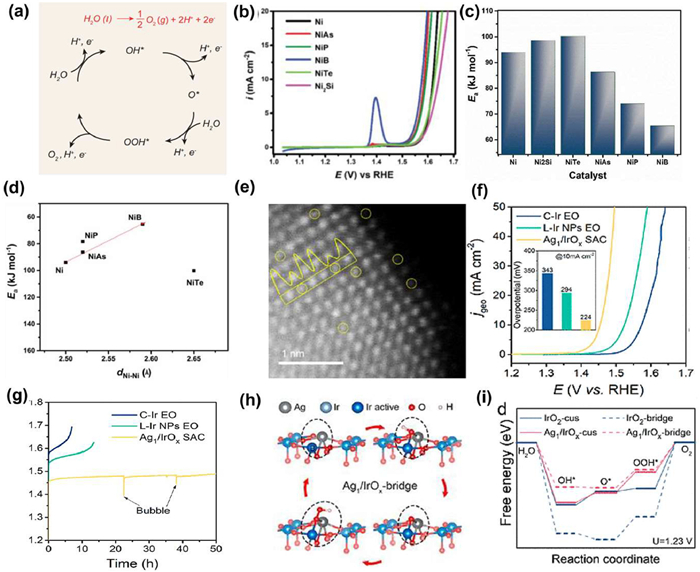
Masa et al. presented a comparative study of the oxygen evolution activity of Ni-metalloid (B, P, Si, As, Te) alloys and discussed experimental insights into the origin of their OER activity enhancement (Fig. 15b). The influence of the metalloid elements on the intrinsic OER activity of Ni was discussed in terms of the activation energy (Ea) of the OER on the various alloys (Fig. 15c). The metalloid changed the lattice structure of Ni, which in turn led to a recent change in the interatomic distance of Ni–Ni (dNi–Ni). The Ea and dNi–Ni indicated that the OER activity was obviously dependent on the lattice properties (Fig. 15d). In the OER process, the surface Ni atom was oxidized to hydroxy nickel oxide, which was the active state of the catalyst. At the same time, the surface quasi-metal was oxidized to the corresponding oxygen anion, which affected the properties of the interface electrode/electrolyte, thus affecting the species that can react with the adsorption/desorption interaction energy [135]. In harsh acidic environment, many OER electrocatalysts are easily dissolved and change surface structure under oxidation OER potential, which ultimately leads to a sharp decline in catalytic performance. Therefore, highly stable catalysts are also important for the development of acidic electrocatalysts for OER. Zhang et al. synthesized an Ag1/IrOx single atom catalyst (SAC) with Ag single atoms embedded in an IrO2 matrix obtained through the oxidation of IrAg single atom alloy (SAA) (Fig. 15e). The Ag1/IrOx SAC delivered a low overpotential of 224 mV at current density of 10 mA/cm2 and a long-term durability better than that of commercial Ir (C-Ir) (Figs. 15f and g). The high performance was attributed to the formation of high-valence Irx+ (x > 4) ions around the single Ag atom (Fig. 15h). DFT calculation revealed that the Ag1/IrOx SAC showed a reduced adsorption energy of OOH species and thus optimized the OER performance (Fig. 15i). Furthermore, the strong Ir−O bonds and low overpotential prevented the loss of the lattice oxygen in the Ag1/IrOx SAC, resulting in high oxygen evolution reaction stability [136].
As the reverse process of OER, ORR pathway can be divided into two types according to the number of electron transfer: one is the four-electron (4e−) reaction pathway, in which oxygen is directly reduced to H2O (or OH−); The second is the two-electron (2e−) reaction pathway, the oxygen is partially reduced to H2O2 (or HO2−) [137-139]. The four-electron ORR process shows a high energy conversion rate, and is the preferred cathode for proton exchange membrane fuel cell (PEMFC) [140,141]. In most cases, the binding pattern of the catalyst surface and its ability to respond to oxygenated species, such as *OOH, *O, and *OH (ORR intermediates), determine the reaction pathway and selectivity of ORR [142-144]. The ORR performance of some recently reported alloy electrocatalysts is summarized in Table S3.
Pt has proven to be the most effective element for catalyzing oxygen reduction reactions (ORR), but its high cost and limited resources have become the biggest obstacle to the further application of PEMFC [34]. At the same time, by alloying Pt with 3d transition metal elements (called M) such as Co, Ni, and Fe, so that M atoms are inserted into the Pt lattice, ORR activity can be improved through ligand effect and stress effect. Zhao et al. prepared PtCo/C catalyst by electrodeposition in N, N-dimethylformamide (DMF) solvent. The coordination of DMF with Pt and Co precursors greatly reduced its deposition potential and promoted the final alloying. At the same time, the combination of physical and chemical characterization indicated that the selective adsorption of DMF on the Pt(111) surface helped to expose more PtCo(111) surfaces, thereby greatly improving the uniformity of particle size and providing higher ORR activity. The experimental results showed that the specific activity of optimized PtCo-1.8/C was more than 5 times that of commercial Pt/C (Figs. 16a and b), and there was almost no change after accelerated degradation test (ADT). According to DFT results, the enhanced intrinsic activity of PtCo-1.8/C towards Pt could be attributed to the relatively weakened adsorption of intermediate O species, and the lowest free energy change for rate-limiting step (i.e., OOH* formation process) with propriate modification on electronic structure and geometric structure by alloying with Co (Fig. 16c) [145]. Shan et al. successfully synthesized a one-dimensional hollow beaded PtNi alloy by solvothermal and post-etching. The catalyst exhibited mass activity of 3.52 A/mgPt and 5.16 mA/cmPt2 and decreased activity by < 1.5% in 50, 000 cycles test (Figs. 16d and e). XAFS and DFT indicated that the excellent performance of the catalyst came from the one-dimensional hollow bead structure fully exposed the active site of the catalyst and maintained good structural stability. On the other hand, the surface coordination and stress made the surface have suitable oxygen intermediate adsorption energy [40].
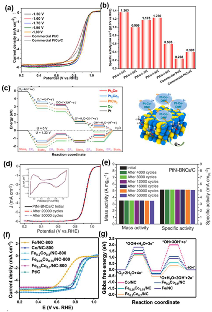
At present, many non-platinum alloy catalysts have also been developed. However, the ORR performance of transition metal-based catalysts is still limited, mainly because transition metals are easy to precipitate in acidic and alkaline media, which greatly reduces the activity and durability of the catalysts. Zhu et al. obtained an excellent FeCo alloy nanoparticle-modified nitrogen-doped mesoporous carbon-oxygen reduction electrocatalyst (FeCo/NC) by pyrolysis of bimetallic MOF composite skeleton. Fe0.25Co0.75/NC-800 catalyst had excellent catalytic activity (E1/2 = 0.86 V, mass activity of 5.22 mA/µgmetal) and excellent durability (Fig. 16f). XPS analysis founded that the significant redistribution of charge around the center of FeCo metal provided good surface energy, which was conducive to the adsorption/desorption process of oxygen intermediates on the surface of alloy NPs, thereby increasing the overall rate of interfacial catalytic processes. Moreover, experimental results and DFT calculations showed that the introduction of adjacent Fe atoms at the Co active site adjusted the electronic structure of the alloy and optimized the adsorption binding energy of oxygen intermediates (*OH, *O and *OOH) (Fig. 16g), thereby greatly improving the catalytic activity and durability [50].
Ammonia is one of the most important chemicals, and its industrial synthesis is mainly carried out using the Haber-Bosch process [146]. The process needs to be carried out at high temperatures and pressures, and the process emits a large amount of CO2 [147]. Therefore, it is of great significance to develop high-efficiency, low-energy and clean ammonia synthesis technology. Electrocatalytic nitrogen fixation can theoretically be carried out at room temperature and pressure, so it is considered a potential alternative to industrial ammonia synthesis [148,149]. The reaction process of NRR involves three basic steps: (1) Adsorption of N2 molecules at the catalytic active site; (2) Cleavage and hydrogenation of N≡N bonds; (3) Desorption of the resulting ammonia molecules (or other intermediate products) from the catalyst surface. At present, the proposed electrocatalytic nitrogen reduction reaction mainly follows two paths in the figure, namely the dissociation path and the association path. However, electrocatalytic ammonia synthesis still faces many problems, such as high overpotential required to activate inert N2 and low NH3 selectivity. Due to the synergistic effect between different metals, alloy catalysts have high activity and selectivity in ammonia synthesis, and have wide versatility. The NRR performance of some recently reported alloy electrocatalysts is summarized in Table S4 (Supporting information).
Precious metals have the disadvantages of high cost, high H affinity, weak N2 adsorption capacity, and poor ammonia selectivity, but alloying with non-precious metals can improve atomic utilization efficiency and promote more catalytically active electronic structures. Jiang et al. obtained a mesoporous amorphous noble metal alloy (iridium-tellurium (IrTe)) using micellar directed synthesis showed excellent performance in electrochemical N2 reduction reaction, the ammonia yield rate was 34.6 µg mg−1 h−1 with a Faradaic efficiency of 11.2% at −0.15 V versus reversible hydrogen electrode in 0.1 mol/L HCl solution, outperforming comparable crystalline and Ir metal counterparts (Figs. 17a and b). According to DFT theoretical simulation, the addition of Te to the IrTe alloy effectively enhanced the adsorption of N2 and reduced the Gibbs free energy of the electrocatalytic N2 reduction reaction rate-limiting step (Fig. 17c) [150]. Fan et al. prepared a monolithic nanoporous NiSb by chemical dealloying of Nb96Sb4 alloy precursors, achieving a high ammonia yield of 56.9 µg mg−1 h−1 and Faradaic efficiency of 48.0% (Fig. 17d). Physical characterizations and adsorption investigations indicated that the electron-deficient Ni supplied electrons to Sb with higher electronegativity, resulting in facilitated nitrogen adsorption on NiSb alloy. DFT calculations revealed that the charge redistribution enhanced activation of the inert N≡N triple bond with lower energy barrier for the rate-determining proton-coupled electron transfer step on NiSb surface, particularly at high hydrogen coverage (Fig. 17e). Furthermore, the Sb atoms separated binding sites to weaken the competitive adsorption between H+ and N2 by adjusting the coordination environment and electronic structure [151]. Shi et al. selected four metals with high NRR activity, Fe, Ni, Mo, Ru and Au to form eight kinds of alloy (MxAu, M = Fe, Mo, Ru, Ni and x = 1 or 3). Through the study of electronic structure, thermodynamics and reaction kinetics, the effects of elemental composition and atomic ratio of Au-based alloys on the catalytic activity and selectivity of electrochemical NRR were studied. First, the adsorption free energy of *N2 and *H was compared to screen catalysts with good selectivity (on Mo3Au(111) ΔG*N < ΔG*H) (Fig. 17f). Subsequently, microkinetic calculations were used to evaluate the catalytic activity of the initial nitrogen activation and hydrogenation processes. Electronic structure analysis based on Bader charge and crystal orbital Hamiltonium confirmed the unique ability of active Mo sites for N2 activation. The kinetics of the reaction (Fig. 17g), Eley-Rideal (E-R) mechanism and Langmuir-Hinshelwood (L-H) mechanism involved in nitrogen hydrogenation reaction were discussed (Fig. 17h). The calculation results showed that among all 8 alloys, Mo3Au(111) had the best electrochemical NRR catalytic performance [152].

The electrochemical reduction reaction (CO2RR) of carbon dioxide can convert CO2 into renewable energy. For example, the reduction of CO2 can be used to produce C1 (CO, CH4, CH3OH, HCOOH, etc.), C2 (C2H4, C2H5OH, and CH3COOH), and C2+ products (C3H7OH) [153-156]. Efficient and inexpensive electrocatalysts are still required to reduce the thermodynamically stable CO2 molecule while suppressing HER. The CO2RR reaction path is complex, involving many proton and electron coupling processes, and the performance of electrocatalysts is usually limited by the volcanic dependence of catalytic activity on CO binding energy [157]. The CO2RR performance of some recently reported alloy electrocatalysts is summarized in Table S4.
Pd can produce formate with almost zero overvoltage and good selectivity, but its high sensitivity to CO poisoning (as an intermediate of side reaction) is severely limited, resulting in rapid loss of activity and poor stability within a few hours. Ag was selected as the second metal in the alloy due to its electron-rich state and weak CO binding strength. Han et al. synthesized Pd-Ag alloy nanowires with high aspect ratio and rough surface, Pd4Ag nanowires could enable the reaction at nearly zero overpotential, maintain high formate selectivity (> 90%) until −0.3 V (Figs. 18a and b). The remarkable stability was due to the improved CO tolerance of Pd4Ag nanowires as evidenced by detailed analysis of CO surface coverage during CO2RR (Fig. 18c). In addition, DFT calculations suggested that the incorporation of Ag in alloy nanowires downshifted the overall d-band center, and diluted the PdHx active sites, which consequently weakened the CO binding on the Pd sites and improved the formate formation by selectively stabilizing the key intermediate (Figs. 18d and e) [158]. Copper is well known as the CO2RR electrocatalyst, and interest in developing catalysts for copper-based alloys has increased in recent years. The production of methane from CO2RR requires the participation of 8 electrons and 8 protons, so it has significant energy absorption. Wang et al. proposed an edge-oriented growth method for large-area two-dimensional Cu2Te nanosheet arrays based on copper foil substrates. Various physicochemical characterizations have observed rich marginal structures and high exposure, providing an important carrier for highly catalytic active sites. These active sites abounding on highly exposed edges of Cu2Te nanosheets greatly promoted the electroreduction of CO2 into CH4 at a potential as low as −0.4 V (versus the reversible hydrogen electrode), while suppressing hydrogen evolution reaction (Fig. 18f). When a flow cell was employed to accelerate the mass transfer, the faradaic efficiency reached ~63% at an applied current density of 300 mA/cm2 (Fig. 18g). Theoretical calculations of the change in free energy (ΔG) from *CO to *CHO have demonstrated that Cu2Te nanosheets have a stronger ability to convert *COOH to *COO, and can achieve CO2 conversion to CH4 with a low energy barrier, resulting in high selectivity (Fig. 18h) [159].

Organic acids and alcohols, such as formic acid, methanol and ethanol, are commonly used chemical fuels in direct liquid fuel cells [160-162]. The FAOR, MOR and EOR performance of some recently reported alloy electrocatalysts are summarized in Table S5 (Supporting information).
The anodic formic acid oxidation reaction (FAOR) of direct formic acid fuel cells (DFAFCs) and the electro-oxidation of HCOOH to CO2 involve the transfer of two electrons, which can be carried out in a double reaction path [163]. The direct route is to directly produce CO2 through the two-step dehydrogenation of formic acid, which is the required reaction route. However, the indirect path is called the dehydration path or CO path. Through this path, formic acid molecules are dehydrated into CO intermediates adsorbed on the active sites, and seriously hinder the catalytic process [164]. Traditional Pt catalysts exhibit poor catalytic performance due to CO poisoning accumulated in the dehydration step, so promoting the direct dehydrogenation path is the key to promote the electrooxidation of formic acid (FAOR) [165]. The multiple components of the designed alloy provide great flexibility for optimizing its FAOR catalytic performance through the synergistic action of multiple metals. Zhan et al. reported a well-defined PtBiPbNiCo hexagonal nanosheet (HEA HPs) as a high-performance electrocatalyst, which was composed of PtBiPb middle entropy core and PtBiNiCo high entropy shell, the specific and mass activities of HEA HPs/C were as high as 27.2 mA/cm2 and 7.1 A/mgPt for FAOR (Fig. 19a). And the membrane electrode assembly (MEA) power density of HEA HPs/C can reach 321.2 mW/cm2, and lifetime can operate 30 h with 55.1% decay of power density, both of which were much better than those of commercial Pd/C (Fig. 19b). Further experiments and theoretical analysis jointly proved that the hexagonal intermetallic core/atomic shell structure and multi-element synergy greatly promoted the direct dehydrogenation pathway of formic acid molecules and inhibited the formation of *CO (Fig. 19c) [166].

As the anode reactions of direct methanol fuel cells (DMFCs) and direct ethanol fuel cells (DEFCs), methanol oxidation reaction (MOR) and ethanol oxidation reaction (EOR) still have slow kinetics of multi-electron transfer process in alcohol and serious intermediate toxicant problems [167]. Because of its large exposed surface area and abundant active sites, alloy nanomaterials are considered as excellent electrocatalysts for the oxidation of alcohol fuel [168]. Xu et al. prepared diamond Pd-Sb rhombohedra catalysts (Pd-Sb RHs) by wet chemical method. Under alkaline conditions for EOR, the mass activity of Pd-Sb RHs/C was higher (3.48 A/mgPd), which was much higher than that of commercial Pd/C (0.39 A/mgPd) catalyst (Fig. 19d). DFT calculation showed that Pd20Sb7 phase of Pd-Sb RHs can not only effectively reduce the barrier energy of ethanol oxidation to acetic acid, but also reduce CO binding, thus improving the resistance to CO poisoning (Fig. 19e) [169]. And Olaya et al. obtained nano-porous gold (NPG) with total residual Ag content less than 1% by dealloying Ag75Au25, and used it as MOR electrocatalyst in 0.1 mol/L NaOH aqueous solution (Fig. 19f) [170]. Kong et al. prepared the selective atomic layer deposition technology to synthesize the Ru-ca-PtNi hybrid catalyst (Ru-ca-PtNi) with surface-cavity coupling of ruthenium single atom and PtNi nanoparticles (PtNi NPs). Ru-ca-PtNi exhibited mass activity for methanol oxidation reaction (MOR) with 2.01 A/mgPt. Also, Ru-ca-PtNi showcased a significant durability with only 16% activity loss after stability test (Figs. 19g–i) [171].
This chapter has provided an extensive overview of the various electrocatalytic applications where alloy nanomaterials have demonstrated their potential. In addition to the aforementioned electrocatalytic applications, electrocatalysis also has other important applications. The following are some noteworthy examples: electrosynthesis of organic compounds, water purification and wastewater treatment, electro catalytic sensors and biosensors, etc. With the deepening of research and the development of technology, more new applications will continue to emerge in the field of electrocatalysis.
In summary, this review systematically summarizes the synthesis methods and strategies of advanced alloy electrocatalysts, and introduces the latest progress in typical electrocatalytic reactions and other aspects. Firstly, the synthesis methods and related formation mechanisms of alloy nanomaterials are reviewed, including co-reduction method, electrochemical deposition method, pyrolytic reduction method, thermal diffusion method, seed mediated method, mechanical ball milling method, and so on. More importantly, several effective factors affecting the performance of advanced alloy electrocatalysts were introduced, including composition, size, morphology, strain engineering, surface engineering, and defect engineering. Alloy nanomaterials exhibit excellent electrocatalytic properties in various reactions, including HER, OER, ORR, FAOR, MOR, EOR, NRR, and CO2RR.
The field of alloy electrocatalysts faces some important problems to be overcome, and improving the catalyst selectivity and efficiency is an important challenge in the current alloy electrocatalysts. On the one hand, the interaction between different metal atoms in alloy electrocatalysts affects the selectivity of the catalyst, which can lead to the generation of side reactions during the reaction process and thus reduce the purity of the reaction products. On the other hand, the catalytic activity of different metals varies, with some metals having higher activity but also being more susceptible to corrosion, a trade-off between activity and stability is needed in this case. Based on the current challenges, we envision the following future development directions.
(1) Preparation of efficient and stable alloy catalysts: Since electrocatalytic reactions usually require efficient and stable catalysts to facilitate the reaction process, the design and preparation of highly active and stable alloy catalysts is a primary challenge in electrocatalysis research. One way to achieve this is by optimizing the interatomic structure, which requires us to control the composition and morphology of alloy electrocatalysts. Also, there is a non-negligible potential for development at the level of surface-active center design and tuning. Therefore, the establishment of a set of efficient and flexible structural modification methods is the key to achieving efficient catalysis in alloy electrocatalysts.
(2) In-depth understanding of the electrocatalytic performance mechanism of alloy materials: In the design and performance optimization process of alloy catalysts, it is crucial to gain an in-depth understanding of the electrocatalytic performance mechanism of alloy materials. Advanced characterization techniques and computational methods are needed to explore the information on the active center, catalytic mechanism and reaction intermediate state of alloy materials in electrocatalytic reactions to achieve precise regulation and improvement of alloy catalyst performance.
(3) Solving the stability problem of alloy catalysts: In electrocatalytic reactions, the stability of alloy catalysts is also an important issue. Due to the influence of external environment, reaction conditions and other factors, alloy catalysts are prone to lattice defects, surface species, electrocatalyst deactivation and other problems, leading to the decrease of catalyst activity and stability. Therefore, it is necessary to further study and solve the stability problems of alloy catalysts and develop and prepare alloy catalysts with long-term stability and efficient catalytic performance.
Alloy nanomaterials have important economic prospects in electrocatalysis, which can improve energy conversion efficiency, reduce catalyst costs, and enhance durability. Through continuous research and technological innovation, we can promote the economic feasibility of alloy nanomaterials in the field of electrocatalysis and make significant contributions to sustainable energy conversion and storage.
The authors declare that they have no known competing financial interests or personal relationships that could have appeared to influence the work reported in this paper.
This work was supported by the National Natural Science Foundation of China (No. 52072153), the Postdoctoral Science Foundation of China (No. 2021M690023), the Postdoctoral Science Foundation of Jiangsu Province (No. 2021K176B), the Graduate Research Innovation Program of Jiangsu Provincial (Nos. KYCX22_3694 and KYCX23_3649), and the Zhenjiang Key R & D Programmes (No. SH2021021).
Supplementary material associated with this article can be found, in the online version, at doi:
S. Ding, M.J. Hülsey, J. Ramírez, N. Yan, Joule 3 (2019) 2897–2929. doi: 10.1016/j.joule.2019.09.015
Y. Yu, T. Ma, H. Huang, Adv. Funct. Mater. 33 (2023) 2213770. doi: 10.1002/adfm.202213770
J. Wang, H. Kong, J. Zhang, et al., Prog. Mater. Sci. 116 (2021) 100717. doi: 10.1016/j.pmatsci.2020.100717
Y. Tong, J. Liu, L. Wang, et al., Adv. Funct. Mater. 32 (2022) 2205654. doi: 10.1002/adfm.202205654
Z. Yang, H. Yang, L. Shang, T. Zhang, Angew. Chem. Int. Ed. 61 (2022) 202113278. doi: 10.1002/anie.202113278
X. Zhang, Z. Sun, R. Jin, et al., Nat. Commun. 14 (2023) 530. doi: 10.1038/s41467-023-36147-2
I.A. Cechanaviciute, R.P. Antony, O.A. Krysiak, et al., Angew. Chem. Int. Ed. 62 (2023) 202218493. doi: 10.1002/anie.202218493
C. Li, N. Su, H. Wu, et al., Inorg. Chem. 61 (2022) 13453–13461. doi: 10.1021/acs.inorgchem.2c01908
Y. Long, H. Xu, J. He, et al., Surf. Interfaces 31 (2022) 102056. doi: 10.1016/j.surfin.2022.102056
M. Zhang, K. Zhang, X. Ai, et al., Chin. J. Catal. 43 (2022) 2987–3018. doi: 10.1016/S1872-2067(22)64103-2
H. Li, C. Guo, J. Long, et al., Chin. J. Catal. 43 (2022) 2746–2756. doi: 10.1016/S1872-2067(22)64090-756
A. Zha, Q. Zha, Z. Li, et al., Rare Met. 42 (2022) 1274–1282.
X. Zhang, C. Wang, K. Chen, et al., Adv. Mater. 35 (2023) 2211512. doi: 10.1002/adma.202211512
G.A. Kamat, J.A. Zamora Zeledon, G. Gunasooriya, et al., Commun. Chem. 5 (2022) 20. doi: 10.1038/s42004-022-00635-1
Z. Shi, J. Li, Y. Wang, et al., Nat. Commun. 14 (2023) 843. doi: 10.1038/s41467-023-36380-9
X. Chen, J. Pu, X. Hu, et al., Small 18 (2022) 2200578. doi: 10.1002/smll.202200578
C. He, T. Bo, B. Wang, J. Tao, Nano Energy 62 (2019) 85–93. doi: 10.1016/j.nanoen.2019.05.009
Y. Xie, X. Chen, K. Sun, et al., Angew. Chem. Int. Ed. 135 (2023) 202301833. doi: 10.1002/ange.202301833
Y. Wang, A.S. Hall, ACS Energy Lett. 5 (2019) 17–22.
G.Q. Sun, W. Zhang, L.L. Liao, et al., Nat. Commun. 12 (2021) 7086. doi: 10.1038/s41467-021-27437-8
Z. Chen, G. Zhang, L. Du, et al., Small 16 (2020) 2004158. doi: 10.1002/smll.202004158
B. Liu, M. Zhang, J. Yang, M. Zhu, Chin. Chem. Lett. 33 (2022) 4679–4682. doi: 10.1016/j.cclet.2022.01.025
T. Xiong, X. Yao, Z. Zhu, et al., Small 18 (2022) 2105331. doi: 10.1002/smll.202105331
F. Bao, Z. Yang, Y. Yuan, et al., Adv. Funct. Mater. 32 (2021) 2108991.
C.H. Chen, D. Wu, Z. Li, et al., ACS Energy Lett. 9 (2019) 1803913.
H. Guo, Z. Fang, H. Li, et al., ACS Nano 13 (2019) 13225–13234. doi: 10.1021/acsnano.9b06244
X. Yang, Q. Wang, S. Qing, et al., ACS Energy Lett. 11 (2021) 2100812.
W. Wang, T. He, X. Yang, et al., Nano Lett. 21 (2021) 3458–3464. doi: 10.1021/acs.nanolett.1c00074
Z. Chen, J. Wen, C. Wang, X. Kang, Small 18 (2022) 2204255. doi: 10.1002/smll.202204255
A.I. Inamdar, H.S. Chavan, B. Hou, et al., Small 16 (2020) 1905884. doi: 10.1002/smll.201905884
R.T. Hannagan, G. Giannakakis, M. Flytzani-Stephanopoulos, E.C.H. Sykes, Chem. Rev. 120 (2020) 12044–12088. doi: 10.1021/acs.chemrev.0c00078
J.T.L. Gamler, H.M. Ashberry, S.E. Skrabalak, K.M. Koczkur, Adv. Mater. 30 (2018) 1801563. doi: 10.1002/adma.201801563
M. Zhou, C. Li, J. Fang, Chem. Rev. 121 (2021) 736–795. doi: 10.1021/acs.chemrev.0c00436
J. Guan, S. Yang, T. Liu, et al., Angew. Chem. Int. Ed. 60 (2021) 21899–21904. doi: 10.1002/anie.202107437
H. Wang, Q.F. He, Y. Yang, Rare Met. 41 (2022) 1989–2001. doi: 10.1007/s12598-021-01926-7
N. Wang, Surf. Interfaces 33 (2022) 102265. doi: 10.1016/j.surfin.2022.102265
J. Kim, B. Lee, Surf. Interfaces 18 (2020) 100440. doi: 10.1016/j.surfin.2020.100440
K.A. Gschneidner, M. Verkade, Prog. Mater Sci. 49 (2004) 411–428. doi: 10.1016/S0079-6425(03)00026-4
Y. Zhou, R. Zhou, X. Zhu, et al., Adv. Mater. 32 (2020) 2000992. doi: 10.1002/adma.202000992
J. Shan, Y. Shi, H. Li, et al., Chem. Eng. J. 433 (2022) 133769. doi: 10.1016/j.cej.2021.133769
J. Su, L. Zhuang, S. Zhang, et al., Chin. Chem. Lett. 32 (2021) 2947–2962. doi: 10.1016/j.cclet.2021.03.082
C. Li, Y. Xu, K. Deng, et al., J. Mater. Chem. A 7 (2019) 3910–3916. doi: 10.1039/C8TA09620A
Y. Lai, L. Dong, R. Liu, et al., Chin. Chem. Lett. 31 (2020) 2437–2441. doi: 10.1016/j.cclet.2020.04.050
S.L.A. Bueno, H.M. Ashberry, I. Shafei, S.E. Skrabalak, Acc. Chem. Res. 54 (2021) 1662–1672. doi: 10.1021/acs.accounts.0c00655
J. Liang, S. Li, Y. Chen, et al., J. Mater. Chem. A 8 (2020) 15665–15669. doi: 10.1039/D0TA01767A
X. Xiao, H. Jeong, J. Song, et al., Chem. Commun. 55 (2019) 11952–11955. doi: 10.1039/C9CC05915F
A.S. Nugraha, V. Malgras, J. Kim, et al., Small Methods 2 (2018) 1800283. doi: 10.1002/smtd.201800283
L. Liu, Y. Wang, Y. Zhao, et al., Adv. Funct. Mater. 32 (2022) 2112207. doi: 10.1002/adfm.202112207
Y. Wang, A. Xu, Z. Wang, et al., J. Am. Chem. Soc. 142 (2020) 5702–5708. doi: 10.1021/jacs.9b13347
G. Zhu, H. Yang, Y. Jiang, et al., Adv. Sci. 9 (2022) 2200394. doi: 10.1002/advs.202200394
F. Zhang, Y. Zhu, Y. Chen, et al., J. Mater. Chem. A 8 (2020) 12810–12820. doi: 10.1039/D0TA04491A
K.J. Jenkinson, A. Wagner, N. Kornienko, et al., Adv. Funct. Mater. 30 (2020) 2002633. doi: 10.1002/adfm.202002633
C.L. Yang, L.N. Wang, et al., Science 374 (2021) 459–464. doi: 10.1126/science.abj9980
X. Zhao, G. Wu, X. Zheng, et al., Angew. Chem. Int. Ed. 62 (2023) 202300879. doi: 10.1002/anie.202300879
J. Guo, H. Wang, F. Xue, et al., J. Mater. Chem. A 7 (2019) 20247–20253. doi: 10.1039/C9TA07519D
C. Shuai, C. He, S. Peng, et al., Adv. Eng. Mater. 23 (2021) 2001098. doi: 10.1002/adem.202001098
H. Chen, J. Liu, X. Wu, et al., Small 18 (2022) 2204100. doi: 10.1002/smll.202204100
T. Gan, Y. Liu, Q. He, et al., ACS Sustain. Chem. Eng. 8 (2020) 8692–8699. doi: 10.1021/acssuschemeng.0c02065
J. Abed, S. Ahmadi, L. Laverdure, et al., Adv. Mater. 33 (2021) 2103812. doi: 10.1002/adma.202103812
T. Mushiana, M. Khan, M.I. Abdullah, et al., Nano Res. 15 (2022) 5014–5023. doi: 10.1007/s12274-022-4186-9
N. Nie, D. Zhang, Z. Wang, et al., Small 17 (2021) 2102879. doi: 10.1002/smll.202102879
S. Wang, B. Xu, W. Huo, et al., Appl. Catal. B: Environ. 313 (2022) 121472. doi: 10.1016/j.apcatb.2022.121472
Q. Wu, M. Luo, J. Han, et al., ACS Energy Lett. 5 (2019) 192–199.
X. Fu, J. Zhang, S. Zhan, et al., ACS Catal. 12 (2022) 11955–1195911955. doi: 10.1021/acscatal.2c02778
J. Greeley, T.F. Jaramillo, J. Bonde, et al., Nat. Mater. 5 (2006) 909–913. doi: 10.1038/nmat1752
Y. Liu, F. Liu, N. Ding, et al., Chin. Chem. Lett. 31 (2020) 2539–2548. doi: 10.1016/j.cclet.2020.03.011
Y. Tang, W. Cheng, Nanoscale 7 (2015) 2040–3372.
P.R. Kumar, P.L. Suryawanshi, S.P. Gumfekar, et al., Surf. Interfaces 12 (2018) 116–123. doi: 10.1016/j.surfin.2018.04.002
S. Mo, P. Peng, Y. Pei, et al., Chin. Chem. Lett. 32 (2021) 2057–2060. doi: 10.1016/j.cclet.2020.11.062
H. Minamihara, K. Kusada, D. Wu, et al., J. Am. Chem. Soc. 144 (2022) 11525–11529. doi: 10.1021/jacs.2c02755
H. Yoon, H.J. Song, B. Ju, et al., ACS Sustain. Chem. Eng. 10 (2022) 15319–15327. doi: 10.1021/acssuschemeng.2c05246
B. Garlyyev, Y. Liang, F.K. Butt, A.S. Bandarenka, Adv. Sustain. Syst. 1 (2017) 1700117. doi: 10.1002/adsu.201700117
I.S. Kwon, I.H. Kwak, G.M. Zewdie, et al., Adv. Mater. 34 (2022) 2205524. doi: 10.1002/adma.202205524
Z. Li, X. Lao, L. Yang, et al., Sci. China Mater. 66 (2022) 150–159.
Y. Wang, J. Zhou, C. Lin, et al., Adv. Funct. Mater. 32 (2022) 2202737. doi: 10.1002/adfm.202202737
L. Sahoo, R. Garg, K. Kaur, et al., Nano Lett. 22 (2022) 246–254. doi: 10.1021/acs.nanolett.1c03704
Z. Ma, Z.P. Cano, A. Yu, et al., Angew. Chem. Int. Ed. 59 (2020) 18334–18348. doi: 10.1002/anie.202003654
M. Zhou, J. Liu, C. Ling, et al., Adv. Mater. 34 (2021) 2106115.
S.H. Han, H.M. Liu, P. Chen, et al., ACS Energy Lett. 8 (2018) 1801326.
Z. Liu, Y. Jiang, Z. Zhang, et al., Nat. Synth. 2 (2023) 119–128. doi: 10.1038/s44160-022-00217-y
M. Tang, S. Luo, K. Wang, et al., Nano Res. 11 (2018) 4786–4795. doi: 10.1007/s12274-018-2063-3
Q. Xu, W. Chen, Y. Yan, et al., Sci. Bull. 63 (2018) 494–501. doi: 10.1016/j.scib.2018.03.013
H. Liu, R. Jia, C. Qin, et al., Adv. Funct. Mater. 33 (2022) 2210626.
M. Qiao, F.Y. Meng, H. Wu, et al., Small 18 (2022) 2204720. doi: 10.1002/smll.202204720
M. Haddadnezhad, W. Park, I. Jung, et al., ACS Nano 16 (2022) 21283–21292. doi: 10.1021/acsnano.2c09349
L. Xiong, X. Zhang, H. Yuan, et al., Angew. Chem. Int. Ed. 60 (2021) 2508–2518. doi: 10.1002/anie.202012631
X. Lyu, Y. Jia, X. Mao, et al., Adv. Mater. 32 (2020) 2003493. doi: 10.1002/adma.202003493
D. Liu, Q. Zeng, C. Hu, et al., ACS Catal. 12 (2022) 9092–9100. doi: 10.1021/acscatal.2c02274
H. Wang, Z.N. Chen, D. Wu, et al., J. Am. Chem. Soc. 143 (2021) 4639–4645. doi: 10.1021/jacs.0c12740
Q. Wang, Y. Lei, D. Wang, Y. Li, Energy Environ. Sci. 12 (2019) 1730–1750. doi: 10.1039/C8EE03781G
W. Wu, Y. Yang, Y. Wang, et al., Chem. Catal. 2 (2022) 3225–3238. doi: 10.1016/j.checat.2022.09.012
R. Chattot, P. Bordet, I. Martens, et al., ACS Catal. 10 (2020) 9046–9056. doi: 10.1021/acscatal.0c02144
H. Peng, J. Ren, Y. Wang, et al., Nano Energy 88 (2021) 106307. doi: 10.1016/j.nanoen.2021.106307
Y. Lu, L. Zhou, S. Wang, Y. Zou, Nano Res. 16 (2022) 1890–1912.
Y. Zhang, X. Chen, W. Wang, et al., Appl. Catal. B: Environ. 310 (2022) 121346. doi: 10.1016/j.apcatb.2022.121346
X. Li, X. Li, C. Liu, et al., Nano Lett. 20 (2020) 1403–1409. doi: 10.1021/acs.nanolett.9b05024
Z. Liu, Z. Zhao, B. Peng, et al., J. Am. Chem. Soc. 142 (2020) 17812–17827. doi: 10.1021/jacs.0c07696
J. Zhang, X. Qu, L. Shen, et al., Small 17 (2021) 2006698. doi: 10.1002/smll.202006698
W. Ge, Y. Chen, Y. Fan, et al., J. Am. Chem. Soc. 144 (2022) 6613–6622. doi: 10.1021/jacs.2c02486
Q. Wang, H. Zhai, L. Liu, et al., J. Magn. Alloy. 10 (2022) 2588–2606. doi: 10.1016/j.jma.2021.11.028
T. Li, Q. Dong, Z. Huang, et al., Adv. Mater. 34 (2022) 2106436. doi: 10.1002/adma.202106436
Q. Ran, S.P. Zeng, M.H. Zhu, et al., Adv. Funct. Mater. 33 (2022) 2211271.
Q. Chen, N. Gong, T. Zhu, et al., Small 18 (2022) 2105696. doi: 10.1002/smll.202105696
Z. Xu, Y. Guo, Z. Yu, et al., Mater. Lett. 325 (2022) 132774. doi: 10.1016/j.matlet.2022.132774
X. Meng, T. Zeng, S. Ma, et al., Adv. Mater. Interfaces 9 (2022) 2101849. doi: 10.1002/admi.202101849
B. Pang, X. Liu, T. Liu, et al., Energy Environ. Sci. 15 (2022) 102–108. doi: 10.1039/D1EE02518J
T. Wu, M. Sun, B. Huang, Small 16 (2020) 2002434. doi: 10.1002/smll.202002434
D. Liu, Y. Zhang, H. Liu, et al., Carbon Energy 5 (2023) 324. doi: 10.1002/cey2.324
S. Luo, L. Zhang, Y. Liao, et al., Adv. Mater. 33 (2021) 2008508. doi: 10.1002/adma.202008508
Z. Hou, C. Cui, Y. Li, et al., Adv. Mater. 35 (2023) 2209876. doi: 10.1002/adma.202209876
C. Li, S. Yan, J. Fang, Small 17 (2021) 2102244. doi: 10.1002/smll.202102244
P. Wang, W. Nong, Y. Li, et al., Appl. Catal. B: Environ. 288 (2021) 119999. doi: 10.1016/j.apcatb.2021.119999
W. Zhang, L. Yang, C. An, et al., J. Mater. Chem. A 8 (2020) 25142–25147. doi: 10.1039/D0TA09937F
M. Wang, H. Yang, J. Shi, et al., Angew. Chem. Int. Ed. 60 (2021) 5771–5777. doi: 10.1002/anie.202013047
L. Ni, Y. Xiao, X. Zhou, et al., Inorg. Chem. 61 (2022) 19552–19566. doi: 10.1021/acs.inorgchem.2c03491
C. Li, D. Zhu, S. Cheng, et al., Chin. Chem. Lett. 33 (2022) 1141–1153. doi: 10.1016/j.cclet.2021.07.057
C. Li, H. Wu, D. Zhu, et al., Appl. Catal. B: Environ. 297 (2021) 120433. doi: 10.1016/j.apcatb.2021.120433
Y. Liu, F. Li, Q. Xia, et al., Nanoscale 10 (2018) 4771–4778. doi: 10.1039/C7NR09435C
S. Huang, A. Shan, R. Wang, Catalysts 8 (2018) 538. doi: 10.3390/catal8110538
Y. Guo, B. Hou, X. Cui, et al., ACS Energy Lett. 12 (2022) 2201548.
Y. He, X. Zhu, C. Zhang, et al., ACS Sustain. Chem. Eng. 11 (2023) 5055–5064. doi: 10.1021/acssuschemeng.2c06888
Y. Zhang, G. Li, Z. Zhao, et al., Adv. Mater. 33 (2021) 2105049. doi: 10.1002/adma.202105049
Y. Xiao, Y. Tao, Y. Jiang, et al., Sep. Purif. Technol. 304 (2023) 122385. doi: 10.1016/j.seppur.2022.122385
Y. Qiu, L. Xin, Y. Li, et al., J. Am. Chem. Soc. 140 (2018) 16580–16588. doi: 10.1021/jacs.8b08356
H. Wang, Y. Yang, F.J. DiSalvo, H.D. Abruña, ACS Catal. 10 (2020) 4608–4616. doi: 10.1021/acscatal.9b05621
W. Moschkowitsch, O. Lori, L. Elbaz, ACS Catal. 12 (2022) 1082–1089. doi: 10.1021/acscatal.1c04948
C. Zhan, Y. Xu, L. Bu, et al., Nat. Commun. 12 (2021) 6261. doi: 10.1038/s41467-021-26425-2
S. Qin, Y. Duan, X.L. Zhang, et al., Nat. Commun. 12 (2021) 2686. doi: 10.1038/s41467-021-22996-2
Y. Duan, Z.Y. Yu, L. Yang, et al., Nat. Commun. 11 (2020) 4789. doi: 10.1038/s41467-020-18585-4
B. Wang, K. Srinivas, Y. Liu, et al., Nano Res. 15 (2022) 3971–3979. doi: 10.1007/s12274-022-4084-1
Y. Chen, J. Xu, P. He, et al., Sci. Bull. 67 (2022) 2449–2486. doi: 10.1016/j.scib.2022.11.027
S. He, M. Shen, E. Wu, et al., Environ. Sci. Ecotechnol. 9 (2022) 100141. doi: 10.1016/j.ese.2021.100141
Y. Lu, K. Huang, X. Cao, et al., Adv. Funct. Mater. 32 (2022) 2110645. doi: 10.1002/adfm.202110645
J. Lee, A. Kumar, T. Yang, et al., Energy Environ. Sci. 13 (2020) 5152–5164. doi: 10.1039/D0EE03183F
J. Masa, S. Piontek, P. Wilde, et al., ACS Energy Lett. 59 (2019) 1900796.
F.F. Zhang, C.Q. Cheng, J.Q. Wang, et al., ACS Energy Lett. 6 (2021) 1588–1595.
N. Zhang, X. Feng, D. Rao, et al., Nat. Commun. 11 (2020) 4066. doi: 10.1038/s41467-020-17934-7
L. Huang, M. Wei, R. Qi, et al., Nat. Commun. 13 (2022) 6703. doi: 10.1038/s41467-022-34444-w
E. Zhou, N. Sun, Y. Jiang, et al., Appl. Surf. Sci. 580 (2022) 152286. doi: 10.1016/j.apsusc.2021.152286
R. Chattot, O. Le Bacq, V. Beermann, et al., Nat. Mater. 17 (2018) 827–833. doi: 10.1038/s41563-018-0133-2
Q. Zeng, S. Chang, M. Wang, et al., Chin. Chem. Lett. 32 (2021) 2212–2216. doi: 10.1016/j.cclet.2020.12.062
F. Zhao, L. Zheng, Q. Yuan, et al., Adv. Mater. 33 (2021) 2103383. doi: 10.1002/adma.202103383
Z. Yu, S. Xu, Y. Feng, et al., Nano. Lett. 21 (2021) 3805–3812. doi: 10.1021/acs.nanolett.1c00147
C. Jin, Y. Lou, J. Liu, F. Wang, ACS Appl. Mater. Interfaces 13 (2021) 45406–45415. doi: 10.1021/acsami.1c10790
L. Zhao, C. Fu, L. Luo, et al., Appl. Catal. B: Environ. 318 (2022) 121831. doi: 10.1016/j.apcatb.2022.121831
Z. Fang, P. Wu, Y. Qian, G. Yu, Angew. Chem. Int. Ed. 60 (2021) 4275–4281. doi: 10.1002/anie.202014302
S. Kelly, A. Bogaerts, Joule 5 (2021) 3006–3030. doi: 10.1016/j.joule.2021.09.009
J. Lan, M. Luo, J. Han, et al., Small 17 (2021) 2102814. doi: 10.1002/smll.202102814
C.Z. He, Y.X. Zhang, J. Wang, L. Fu, Rare Met. 41 (2022) 3456–3465. doi: 10.1007/s12598-022-02059-1
B. Jiang, H. Xue, P. Wang, et al., J. Am. Chem. Soc. 145 (2023) 6079–6086. doi: 10.1021/jacs.2c10637
G. Fan, W. Xu, J. Li, et al., Adv. Mater. 33 (2021) 2101126. doi: 10.1002/adma.202101126
J.L. Shi, S.Q. Xiang, D.J. Su, et al., ChemSusChem 14 (2021) 4525–4535. doi: 10.1002/cssc.202101462
Y. Qin, W. Zhang, K. Guo, et al., Adv. Funct. Mater. 30 (2020) 1910107. doi: 10.1002/adfm.201910107
S. Shen, X. Peng, L. Song, et al., Small 15 (2019) 1902229. doi: 10.1002/smll.201902229
J. Jiao, R. Lin, S. Liu, et al., Nat. Chem. 11 (2019) 222–228. doi: 10.1038/s41557-018-0201-x
J. He, X. Wang, S. Jin, et al., Chin. J. Catal. 43 (2022) 1306–13151306. doi: 10.1016/S1872-2067(21)63936-0
J. Zhao, P. Zhang, T. Yuan, et al., J. Am. Chem. Soc. 145 (2023) 6622–6627. doi: 10.1021/jacs.2c12006
N. Han, M. Sun, Y. Zhou, et al., Adv. Mater. 33 (2021) 2005821. doi: 10.1002/adma.202005821
H. Wang, G. Zhan, C. Tang, et al., ACS Nano 17 (2023) 4790–4799. doi: 10.1021/acsnano.2c11227
Z. Li, L. Zhai, Y. Ge, et al., Natl. Sci. Rev. 9 (2022) 142.
J. Wang, B. Wang, W. Zhang, et al., Appl. Surf. Sci. 587 (2022) 152867. doi: 10.1016/j.apsusc.2022.152867
C. Zhai, Y. Chen, X. Huang, et al., Environ. Funct. Mater. 1 (2022) 219–229.
Y. Zhou, Y. Yang, X. Zhu, et al., Adv. Funct. Mater. 32 (2022) 2201872. doi: 10.1002/adfm.202201872
M. Tang, W. Chen, S. Luo, et al., J. Mater. Chem. A 9 (2021) 9602–9608. doi: 10.1039/D1TA01123E
S. Luo, W. Chen, Y. Cheng, et al., Adv. Mater. 31 (2019) 1903683. doi: 10.1002/adma.201903683
Y. Xie, X. Chen, K. Sun, et al., Angew. Chem. Int. Ed. 62 (2023) 202301833. doi: 10.1002/anie.202301833
J. Chang, G. Wang, X. Chang, et al., Nat. Commun. 14 (2023) 1346. doi: 10.1038/s41467-023-37011-z
X. Xu, K. Lin, F. Jia, et al., ACS Appl. Energy Mater. 5 (2022) 10233–10239. doi: 10.1021/acsaem.2c01952
B. Xu, T. Liu, X. Liang, et al., Adv. Mater. 34 (2022) 2206528. doi: 10.1002/adma.202206528
A.R. Silva Olaya, F. Kühling, C. Mahr, et al., ACS Catal. 12 (2022) 4415–4429. doi: 10.1021/acscatal.1c05160
F. Kong, X. Liu, Y. Song, et al., Angew. Chem. Int. Ed. 61 (2022) 202207524. doi: 10.1002/anie.202207524

Figure 1 Schematic diagram summary of synthesis methods, morphologies and applications of alloy electrocatalysts.

Figure 2 (a) Schematic illustrations of various alloy structures. (b) Schematic diagram of common crystal structure types in metals. (c) The electronegativity vs. the metallic radius for a coordination number of 12 (Darken-Gurry) map for Ta as the solvent. Copied with permission [38]. Copyright 2004, Elsevier.

Figure 3 Schematic illustration showing synthesis of (a)NiRu/TCN. Copied with permission [41]. Copyright 2021, Elsevier. (b) PtPdNiP MNs. Copied with permission [42]. Copyright 2019, Royal Society of Chemistry. (c) o-Pd2Sn. Copied with permission [45]. Copyright 2020, Royal Society of Chemistry. (d) Pd@Pt. Copied with permission [46]. Copyright 2019, Royal Society of Chemistry.

Figure 4 Schematic illustration showing synthesis of (a) mesoporous AuCuNi ternary alloy film. Copied with permission [47]. Copyright 2018, Wiley-VCH. (b) PtCu/WO3@CF. Copied with permission [48]. Copyright 2022, Wiley-VCH. (c) FeCo/NC catalyst. Copied with permission [50]. Copyright 2022, Wiley-VCH. (d) RuCo@NC. Copied with permission [51]. Copyright 2020, Royal Society of Chemistry.

Figure 5 Schematic illustration of (a) Pt-based i-NPs on S-C. Copied with permission [53]. Copyright 2021, Science. (b) RuBi SAA/Bi@OG. Copied with permission [54]. Copyright 2023, Wiley-VCH. (c) Pt1/Co SAA. Copied with permission [58]. Copyright 2020, American Chemical Society. (d) (NiCo)3Se4 after SABM. Copied with permission [59]. Copyright 2021, Wiley-VCH.

Figure 6 (a) Computational prediction of desirable composition for HER electrocatalyst. Copied with permission [64]. Copyright 2022, American Chemical Society. (b) Computational high-throughput screening for |ΔGH| on 256 pure metals and surface alloys. Copied with permission [65]. Copyright 2006, Nature Publishing Group.

Figure 7 (a) TEM images. (b) CO conversion of PtAg-x nanoalloys in different states. Copied with permission [69]. Copyright 2021, Elsevier. (c) HAADF-STEM image of IrPdPtRhRu HEA NPs. Copied with permission [70]. Copyright 2022, American Chemical Society. (d) TEM images of PtMo/C annealed at different temperatures. Copied with permission [71]. Copyright 2022, American Chemical Society.

Figure 8 (a) HRTEM image of (MoVNb)Se2. [73] Copyright 2022, Wiley-VCH. (b) STEM image of the PdAgCu NSAs. Copied with permission [74]. Copyright 2022, Springer Nature. (c) TEM image of RuCo NSs. Copied with permission [75]. Copyright 2022, Wiley-VCH. (d, e) HRTEM and TEM images of the PdNi TWNs. Copied with permission [76]. Copyright 2022, American Chemical Society. (f) The fcc Pd3Sn nanorods. Copied with permission [78]. Copyright 2020, Springer Nature.

Figure 9 TEM images of (a) Pt54Rh4Cu42 CNBs. Copied with permission [79]. Copyright 2018, Wiley-VCH. (b) Pd@Pt–Ni octahedra. Copied with permission [80]. Copyright 2023, Springer Nature. (c) Pt-Ni-Cu ERDs. Copied with permission [81]. Copyright 2018, Springer Nature. (d) Au@AgPd NFs. Copied with permission [43]. Copyright 2020, Elsevier. (e) PtCuRu NFs. Copied with permission [84]. Copyright 2022, Wiley-VCH. SEM images of (f) Pt DWFs. Copied with permission [85]. Copyright 2022, American Chemical Society. (g) Ag3Au nanoframes. Copied with permission [85]. Copyright 2021, Wiley-VCH. TEM images of (h) Pt-Ni/G. Copied with permission [87]. Copyright 2020, Wiley-VCH. (i) CuPd@NiPd. Copied with permission [88]. Copyright 2022, American Chemical Society.

Figure 10 (a) Schematic illustration showing synthesis, (b) TEM, (c) HADDF-STEM images and (d) electrocatalytic NITRR performance of VCu-Au1Cu SAAs. Copied with permission [95]. Copyright 2022, Elsevier. (e, f) TEM images, (g) EPR spectra of defective Cu-Bi, and (h) the urea concentrations of catalysts. Copied with permission [91]. Copyright 2022, Elsevier.

Figure 11 (a) Schematic illustration showing synthesis, (b) TEM, (c) LSV curves (iR-corrected) of FeNi3-N-350-t. Copied with permission [103]. Copyright 2021, Wiley-VCH. (d) Schematic illustration of preparation process, (e) TEM image, and (f) comparisons of electrochemical behaviors of N-Pd60Cu40 NS with reported PdCu-based catalysts. Copied with permission [105]. Copyright 2022, Wiley-VCH.

Figure 12 (a) Schematic illustration of the synthesis and (b) enlarged HAADF-STEM view of the L10-FePt core of FePt@PtBi. Copied with permission [34]. Copyright 2021, Wiley-VCH. (c) HAADF‐STEM image and (d) element mapping analysis of CuPd-2. Copied with permission [108]. Copyright 2023, Wiley-VCH. (e) STEM-EDS elemental mappings of CuAu@2LCS. Copied with permission [112]. Copyright 2021, Elsevier. (f, g) HAADF image of Ru88Pt12 nanowires. Copied with permission [113]. Copyright 2020, Royal Society of Chemistry.

Figure 13 (a) Catalytic cycle of HER. Copied with permission [119]. Copyright 2017, National Science Review. Polarization curves of Rh@Pt2L, Pt/C, and RhPt alloy electrocatalysts in (b) 1.0 mol/L KOH and (c) 1.0 mol/L PBS. (d) The hydrogen adsorption Gibbs free energy, and (e) energy diagrams of a Volmer–Heyrovsky process. Copied with permission [120]. Copyright 2022, Wiley-VCH. (f) Spherical aberration-corrected HRTEM. HER polarization plots under (g) alkaline and (h) alkaline conditions of FeCoNiWMo HEA NPs. (i) Models of Co-site, Mo-site, Ni-site and W-site, respectively. Copied with permission [121]. Copyright 2023, American Chemical Society.

Figure 14 (a) HAADF-STEM image, (b) LSV for HOR, (c) normalized mass activity and specific activity at an overpotential of 50 mV and (d) PDOSs on HEA SNWs. Copied with permission [127]. Copyright 2021, Nature. (e) SEM image, (f) LSV for HOR, (g) the Bader charge analysis, (h) HBEs and OHBEs and (i) free energy diagrams for reaction pathways on Ni5.2WCu2.2, Ni17W3, Ni. Copied with permission [128]. Copyright 2021, Nature.

Figure 15 (a) Catalytic cycle of OER in water electrolysis. Copied with permission [119]. Copyright 2017, National Science Review. (b) LSV, (c) activation energy of the OER and (d) plot of function Ea and dNi–Ni in Ni-metalloid alloys. Copied with permission [135]. Copyright 2019, Wiley-VCH. (e) High-resolution aberration-corrected HAADF-STEM image, (f) LSV, (g) chronopotentiometry curve, (h) reaction path diagram and (i) calculated free energy diagrams of Ag1/IrOx SAC. Copied with permission [136]. Copyright 2021, American Chemical Society.

Figure 16 (a) The LSV, (b) the summarized specific activity value and (c) ORR energy profiles on the series of geometry-optimized PtCo slabs at U = 0 V and U = 1.23 V, respectively. Copied with permission [145]. Copyright 2022, Elsevier. (d) LSV and (e) mass and specific activity evolutions for PtNi-BNCs/C. Copied with permission [40]. Copyright 2019, Science. (f) LSV and (g) free energy diagrams with U = 0.385 V for ORR process. Copied with permission [50]. Copyright 2022, Wiley-VCH.

Figure 17 (a) UV−vis absorption spectra, (b) the ammonia yield rate and corresponding FEs and (c) free energy diagram of the NRR on the Ir and IrTe. Copied with permission [150]. Copyright 2023, American Chemical Society. (d) NH3 yield rates and FEs of NiSb, (e) Gibbs free-energy profiles of NRR. Copied with permission [151]. Copyright 2021, Wiley-VCH. (f) Adsorption free energy of N2 and H, (g) potential energy curves on Mo3Au(111) facet, (h) the comparison of limiting potential of HER and NRR based on Eley-Rideal mechanism and Volmer-Heyrovsky mechanism. Copied with permission [152]. Copyright 2021, Wiley-VCH.

Figure 18 (a) LSV in CO2 or N2, (b) potential-dependent formate selectivity, (c) integrated CO oxidation charge and corresponding CO surface coverage, (d) PDOS, and (e) energetic reaction pathways of CO2RR of Pd4Ag. Copied with permission [158]. Copyright 2021, Wiley-VCH. (f) FEs of CO2RR, (g) electrolytic reduction of CO2 to CH4 over the Cu2Te nanosheet, and (h) free energy diagrams of hydrogenation steps. Copied with permission [159]. Copyright 2023, American Chemical Society.

Figure 19 (a) Mass and specific activities, (b) steady-state polarization and power density curves, and (c) Gibbs free energy diagram of HEA HPs/C for FAOR. Copied with permission [166]. Copyright 2022, Wiley-VCH. (d) Cyclic voltammograms (CVs), (e) specific activities and mass activities, and (f) energy profile ΔE (eV) throughout EOR based on the Pd20Sb7. Copied with permission [169]. Copyright 2022, Wiley-VCH. (g) CV curves, (h) mass activities, and (i) reaction profile for MOR on different surfaces of Ru-ca-PtNi for MOR. Copied with permission [171]. Copyright 2022, Wiley-VCH.

 扫一扫看文章

扫一扫关注我们
 DownLoad:
 下载:
下载: