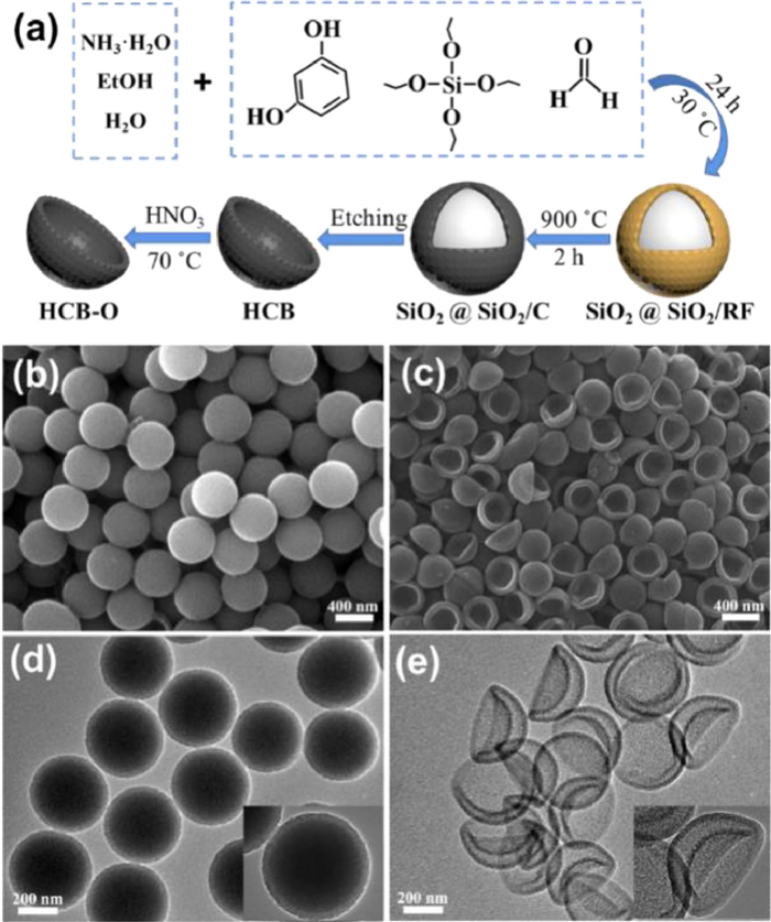
Figure 1.
The morphologies and structures of the synthetic materials. (a) Schematic illustration for preparation of HCB-O. SEM of (b) SiO2@SiO2/C and (c) HCB-O. TEM of (d) SiO2@SiO2/C and (e) HCB-O.
Oxygen functional groups modified amorphous hollow carbon bowls for pseudocapacitive Zn-ion storage
Gongxun Yu , Fenghui Yang , Xu Han , Qiongyao Song , Jiangtao Zheng , Ying Qi , Tianming Chen , Qian Shen , Jingxia Qiu , Sheng Li

Higher energy and power densities are highly required for rechargeable energy storage devices. However, by now, there is plenty of room for improvements for the current commercial ones [1-5]. For example, traditional batteries are hindered by the low power density and potential safety issues from the organic electrolyte systems; meanwhile, supercapacitors eagerly require higher energy density. Thus, to combine the advantages of batteries and supercapacitors, Zn-ion hybrid supercapacitors (ZHSCs) have been proposed and developed [6-11], in which a pair of hybrid electrodes (capacitor-type cathode and battery-type anode) with aqueous electrolyte could enable both high energy and power densities [12-14]. Compared with other ions such as Li+ or Na+, a Zn ion can carry 2 electrons during cycling and work well in aqueous electrolytes. As the most used battery-type anode of ZHSCs, metal Zn with high theoretical specific capacity and good deposition/stripping efficiency is considered reasonably practical [15-17]. The development of an excellent capacitive cathode has thus become the short slab of a barrel for advanced ZHSCs.
Carbon-based materials have been widely discussed and applied as capacitive cathodes for ZHSCs, as it is low-cost, environmentally friendly, and most importantly, controllable and adjustable [18-24]. By now, achieving both high energy and high power with carbon electrodes is still challenging, which is limited by their intrinsic properties. In response to this bottleneck, it is quite necessary to design carbon materials for advanced electrodes.
Among various types of carbon materials, hollow carbon spheres (HCS) can be quite promising due to their large specific surface area, the rich interconnected pores and their unique hollow cavities. The hollow structure and pores can be used as ions-reservoirs to shorten the transmission distance of Zn2+, making them excellent capacitive electrodes [25-27]. As a unique form of HCS, hollow carbon bowls (HCB) have all the advantages of HCS but even better conductivity and higher volume energy density. It has also shown impressive electrochemical performance when used as the electrode material for supercapacitors [28-31].
It should be noted that the capacitance provided by only relying on the electric double layer on the surface of the carbon material is still limited. In order to further improve the energy density of carbon materials, materials modification strategies with pseudocapacitive properties are necessary [32]. Introducing oxygen functional groups can be quite an effective strategy to enhance the pseudocapacitance contribution and surface wettability of carbon materials [33-36]. This strategy may increase the polar sites on the surface of the carbon, providing more active sites for ion storage. Besides, introducing O in carbon may bring more defects and distortions for the electrode material, increasing the ion transport and electronic conductivity. In addition, compared with other methods, such as selective doping or controlling carbon crystallization degrees, introducing functional groups can be simple and universal to many kinds of carbon without changing their inherent structures. Furthermore, we also assume that carbonyl groups can be electrochemically positive for reversibly Zn ions storage. Nevertheless, by now, the ion storage mechanism between oxygen functional groups and Zn2+ is unclear, and applying this strategy in ZHSCs has rarely been explored.
In this work, a hollow carbon bowls material modified by oxygen groups (HCB-O) has been customized for ZHSCs. Fig. 1a briefly shows the preparation procedure of HCB-O. In the mixed solution, intermediates with core-shell structure were synthesized using resorcinol and formaldehyde as carbon sources and tetraethyl orthosilicate (TEOS) as template agents (SiO2@SiO2/RF). Then, it was calcined and etched to form HCB. The prepared carbon was acid-treated to obtain oxidized HCB-O; more details can be found in the experimental section.
It should be noted here that the key to preparing bowl-like hollow carbon is closely related to carbon crystallinity. When the carbonization temperatures are controlled at less than 1000 ℃ (900 ℃ in this case), the graphitization degree of the carbon is relatively low, and there is only distortional and enlarged lattice space in an amorphous carbon structure. Thus hollow bowl structures with more defects can be obtained instead of spheres.
As previously discussed, the porous carbon layer can not only increase the specific surface area to promote the adsorption of Zn2+ but also enhance their diffusion rates. In addition, introducing oxygen groups can improve the pseudocapacitance contribution and surface wettability of HCB-O. As expected, the HCB-O can deliver improved electrochemical performance for the ZHSCs. The mechanism study also shows that the Faradic chemical adsorptive pseudocapacitance contribution of HCB-O can be from the rapid reactions between oxygen groups and Zn2+.
The morphology and structure of the materials were then characterized by scanning electron microscope (SEM) and transmission electron microscope (TEM) (Fig. 1 and Fig. S1 in Supporting information). The SiO2@SiO2/RF with the spherical core-shell structure is shown in Figs. S1a and c. As shown in Figs. 1b and d, SiO2@SiO2/C keeps the spherical core-shell structure with a core diameter of about 400 nm and a shell thickness of about 30 nm. It shows that the morphology and the size of SiO2@SiO2/C did not change significantly after high-temperature calcination. After removing the SiO2 core by HF etching, the original hollow carbon shell collapses to form bowl-like structures (Figs. 1c and e). Meanwhile, the micro-mesoporous structure is also formed. Compared with the spherical structure, the bowl-shaped carbon can increase the contact area and improve the conductivity, retaining rich pores simultaneously. This structure is not only beneficial to the rapid transfer of electrons and ions but also can provide rich adsorption sites, making HCB-O a promising electrode material.
The crystal structure characterization of the materials was carried out by X-ray diffraction (XRD), as shown in Fig. 2a. The XRD patterns of HCB and HCB-O display two typical diffraction peaks at 2θ values of about 23°, which can be assigned to the (002) lattice of the crystalline. The broad peak indicates that both HCB and HCB-O have distortional and enlarged lattice space than the graphitic carbon. They are both in amorphous states. In Fig. 2b, the D-band and G-band peaks in the Raman spectrum can be found, and the intensity ratio between them (ID/IG) is commonly used to evaluate the disordered degree of carbon materials [37,38]. The ID/IG value of HCB-O (1.002) is similar to that of HCB (1.007). Along with the result in XRD, it shows that the oxidation of HCB-O almost did not change the carbon's inherent structure. It also could be inferred that oxygen mainly exists as functional groups on the surface instead of doping.
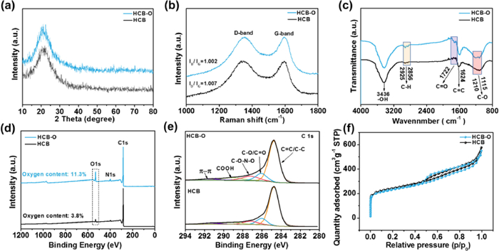
The oxygen functional groups of HCB-O are then characterized. The FTIR spectra of HCB and HCB-O are shown in Fig. 2c. From both HCB and HCB-O, some similar bonds can be observed, such as —OH, C—H, C=O, C=C and C—O [39,40]. However, different from HCB, the COOH peak at 1722 cm−1 of HCB-O is more apparent, and a new C—O peak is generated at 1210 cm−1. The results indicate that the oxygen groups were successfully introduced into HCB-O.
The X-ray photoelectron spectroscopy (XPS) test further supports this observation. The XPS survey in Fig. 2d shows that the surfaces of HCB and HCB-O are mainly composed of C, O, and a small amount of N. After acid treatment, the O proportion significantly increases from 3.8% to 11.3%. The C 1s XPS spectra of HCB and HCB-O are shown in Fig. 2e, which can be divided into five peaks, corresponding to the peaks of C—C/C=C, C—O/C=O, C—O—N—O, COOH and π-π bond at the binding energies of 284.57, 285.97, 287.15, 288.9 and 291.2 eV, respectively. Among them, the relative content of C—O/C=O in HCB-O (9.57%) is also higher than that of HCB (5.38%); other oxygen groups are also slightly higher. It illustrates that the acid treatment successfully improves the oxygen content of HCB.
The specific surface area and pore size distribution of HCB and HCB-O were tested by BET (Fig. 2f and Fig. S2 in Supporting information). The specific surface areas of HCB and HCB-O are 870 m2/g and 826 m2/g, respectively. The little decreased specific surface area of HCB-O is mainly attributed to the covering of oxygen functional groups on carbon bowls. Moreover, the distribution of pore sizes of HCB and HCB-O is hierarchical, and their pore sizes are around 0–2 nm and 2–10 nm. The mesopore structure is beneficial for rapid ion transport, thus enhancing rate capability [41]. Besides, it is found that the large specific surface area and rich pore volume could promote electrolyte infiltration and facilitate the adsorption and desorption processes of ions [42].
In order to evaluate the electrochemical performance of HCB and HCB-O, the ZHSCs (denoted as HCB//Zn and HCB-O//Zn) were assembled. The CV and GCD were used to evaluate the electrochemical properties of the ZHSCs in the voltage window of 0.2–1.8 V [43,44]. Fig. 3a shows that the CV curves of HCB and HCB-O are mainly quasi-rectangular, indicating their capacitive energy storage behaviors. It should be noted that the CV curve of HCB-O has a pair of more obvious broad redox peaks. The area enclosed by the CV curve of HCB-O is significantly larger than that of HCB, showing a higher capacitance. The extra part of HCB-O is found to be contributed by the broad redox peaks, which correspond to the pseudocapacitive reactions of the surface oxygen, possibly relating to the C=O or C—O groups. Moreover, when the scanning rates increased, there was no apparent deformation of the CV curves of both the HCB and HCB-O, indicating no severe polarization under high current densities (Figs. S3a and b in Supporting information).
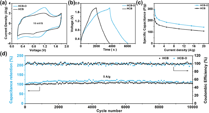
The GCD curves of HCB and HCB-O display typical capacitive quasi-linear symmetry (Fig. 3b, Figs. S3c and d in Supporting information). The specific capacitances of HCB and HCB-O under different current densities were calculated and shown in Fig. 3c. The HCB electrode delivers 216 F/g and 108 F/g under the current densities of 0.2 A/g and 20 A/g, respectively. In contrast, the HCB-O electrode can present significantly higher specific capacitances of 295 F/g and 143 F/g. Although both electrodes show excellent rate performance, the HCB-O is about 30% higher than that of HCB at all current densities. It indicates that oxygen functional group modification is a practical method to improve the capacitance of carbon materials. The long cycle stability performance of ZHSCs is shown in Fig. 3d. The capacitance retention of HCB//Zn and HCB-O//Zn have no apparent attenuation after 10,000 cycles at the current density of 5 A/g, which shows excellent cycle stability for both the ZHSCs.
In order to study the energy storage mechanism of HCB-O//Zn, the electrodes at different cut-off voltages during charge and discharge are further characterized. Fig. 4a shows the third cycle GCD curve of HCB-O//Zn, which was charged from 0.2 V to 1.8 V and then discharged to 0.2 V, the cathode/anode materials at four different state points of A (0.2 V), B (0.8 V), C (1.8 V), and D (0.8 V) are chosen and studied. The XRD spectra of the HCB-O cathode at different states are shown in Fig. 4b, and the peaks of Zn4SO4(OH)6·3H2O, the PTFE binder and amorphous carbon can be distinguished. The Zn4SO4(OH)6·3H2O can be observed in states A and B but not in C and D, indicating it is formed with Zn disposition and gradually disappears during charging. As shown in SEM images (Fig. S5 in Supporting information), flake-like materials are observed on the cathode surface at states A and B while disappearing at states C and D. This is consistent with the results of Zn4SO4(OH)6·3H2O in XRD spectra. The element mapping test of the HCB-O cathode in state A was carried out, showing that the main elements are C, O, Zn and S, corresponding to elements in Zn4SO4(OH)6·3H2O. It shows that Zn ions are significantly affected by the O-containing anionic groups on the surface of the discharged product. The ex-XRD spectra of the Zn anode at different states are shown in Fig. 4c, and only Zn peaks can be found.
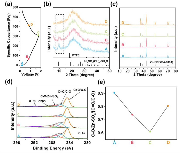
Further, XPS was used to understand the surface chemical structure transformation of the HCB-O cathode during the charge and discharge process. The C 1s XPS spectra of the HCB-O cathode at different states are shown in Fig. 4d. With consideration of the ex-situ XRD data, the binding energies at 284.57, 285.97, 287.15, 288.90 and 291.64 eV correspond to C—C/C=C, C=O/C—O, C—O—Zn—SO4, COO and π-π, respectively. It can be found that the proportions of C=O/C—O and C—O—Zn—SO4 changed cyclically during charge and discharge. As shown in Fig. 4e, the ratios of C—O—Zn—SO4 to C=O/C—O decrease gradually during charging and increase during discharging. This change indicates that C=O and C—OH would combine with Zn2+ to form a C—O—Zn bond during discharge and then releases Zn2+ to re-form C=O and C—OH during charging. Combined with the analysis results of C 1s and previous studies [9,45,46], it can be inferred that the following reactions occur in the discharge process, illustrating that carbonyl groups could be influential for reversible Zn redox storage:
|
|
(1) |
|
|
(2) |
Therefore, the pseudocapacitance of oxygen functional groups is mainly contributed by the reactions of C=O/C—O with Zn ions. It is also in line with the pair of CV peaks in Fig. 3a. The ex-situ FT-IR spectra also showed that the oxygen functional group changed reversibly during the charge and discharge processes. As shown in Fig. S6 (Supporting information), the C—OH at 1235 cm−1 and C=O at 1722 cm−1 gradually disappeared during the charging process and appeared again during the discharge process. In addition, the C—O at 1047–1095 cm−1 did not change much during the charge and discharge process. It also proved the conclusions of the proposed reactions.
In summary, the HCB-O has been developed and shows an enhanced and remarkable electrochemical performance according to its unique structures and surface oxygen modification. The large specific surface area, amorphous state, porous structure and good conductivity of HCB-O can present an excellent electric double-layer capacitance. Moreover, the oxygen functional groups can further improve their pseudocapacitance with good cycling stability. The energy storage mechanism study indicated that the reaction from surface chemical redox reactions could provide a significant pseudocapacitance contribution. It will promote an understanding of the preparation of bowl-like structures and the Zn2+ storage mechanism of oxygen functional groups and provide a reference for designing ZHSCs carbon cathode materials.
Authors declare that they have no conflict of interest.
This work was financially supported by the National Natural Science Foundation of China (Nos. 22075109, 22279056) and the Jiangsu Provincial Department of Science and Technology (No. BK20220010).
Supplementary material associated with this article can be found, in the online version, at doi:
X. Zhang, Z. Pei, C. Wang, et al., Small 15 (2019) e1903817. doi: 10.1002/smll.201903817
M. Shao, C. Sun, T. Chen, et al., J. Energy Chem. 65 (2022) 127–132. doi: 10.1016/j.jechem.2021.05.037
S. Li, C. Huang, L. Gao, et al., Angew. Chem. Int. Ed. 50 (2022) e202211478.
Y. Tan, S. Li, X. Zhao, et al., Adv. Energy Mater. 12 (2022) 2104001. doi: 10.1002/aenm.202104001
X. Li, X. Liu, Y. Xiang, et al., Chin. Chem. Lett. 33 (2022) 3197–3202. doi: 10.1016/j.cclet.2021.10.014
V. Vijayakumar, M. Ghosh, M. Kurian, et al., Small 16 (2020) e2002528. doi: 10.1002/smll.202002528
S. Wang, Q. Wang, W. Zeng, et al., Nano-Micro Lett. 11 (2019) 70. doi: 10.1007/s40820-019-0301-1
Z. Li, D. Chen, Y. An, et al., Energy Storage Mater. 28 (2020) 307–314. doi: 10.1016/j.ensm.2020.01.028
Y. Shao, Z. Sun, Z. Tian, et al., Adv. Funct. Mater. 31 (2020) 2007843.
Q. Wang, S. Wang, X. Guo, et al., Adv. Electron. Mater. 5 (2019) 1900537. doi: 10.1002/aelm.201900537
P.A. Maughan, N. Tapia-Ruiz, N. Bimbo, Electrochim. Acta 341 (2020) 136061. doi: 10.1016/j.electacta.2020.136061
H. He, J. Lian, C. Chen, Q. Xiong, M. Zhang, Chem. Eng. J. 421 (2021) 129786. doi: 10.1016/j.cej.2021.129786
Z. Song, G. Zhang, X. Deng, et al., Adv. Funct. Mater. 32 (2022) 2205453. doi: 10.1002/adfm.202205453
L. Miao, Y. Lv, D. Zhu, et al., Chin. Chem. Lett. 34 (2023) 107784. doi: 10.1016/j.cclet.2022.107784
G. Sun, H. Yang, G. Zhang, et al., Energy Environ. Sci. 11 (2018) 3367–3374. doi: 10.1039/C8EE02567C
G.H. An, J. Hong, S. Pak, et al., Adv. Energy Mater. 10 (2019) 1902981.
Z. Song, G. Zhang, X. Deng, et al., Nano-Micro Lett. 14 (2022) 53. doi: 10.1007/s40820-022-00792-x
L. Dong, X. Ma, Y. Li, et al., Energy Storage Mater. 13 (2018) 96–102. doi: 10.1016/j.ensm.2018.01.003
Z. Liu, G. Li, T. Cui, et al., J. Solid State Electrochem. 22 (2017) 91–101.
Z. Huang, T. Wang, H. Song, et al., Angew. Chem. Int. Ed. 60 (2021) 1011–1021. doi: 10.1002/anie.202012202
F. Wan, L. Zhang, X. Wang, et al., Adv. Funct. Mater. 28 (2018) 1804975. doi: 10.1002/adfm.201804975
L. Han, H. Huang, X. Fu, et al., Chem. Eng. J. 392 (2020) 123733. doi: 10.1016/j.cej.2019.123733
H. Zhou, C. Liu, J.C. Wu, et al., J. Mater. Chem. A 7 (2019) 9708–9715. doi: 10.1039/C9TA01256G
H. Liang, R. Shi, Y. Zhou, et al., ACS Energy Lett. 7 (2022) 4381–4388. doi: 10.1021/acsenergylett.2c02203
S. Chen, G. Yang, X. Zhao, et al., Front. Chem. 8 (2020) 663. doi: 10.3389/fchem.2020.00663
H. Zhang, O. Noonan, X. Huang, et al., ACS Nano 10 (2016) 4579–4586. doi: 10.1021/acsnano.6b00723
J. Liu, S.Z. Qiao, H. Liu, et al., Angew. Chem. Int. Ed. 50 (2011) 5947–5951. doi: 10.1002/anie.201102011
W. Ye, L. Wang, Y. Yin, et al., ACS Energy Lett. 6 (2021) 2145–2152. doi: 10.1021/acsenergylett.1c00456
R. Fei, H. Wang, Q. Wang, et al., Adv. Energy Mater. 10 (2020) 2002741. doi: 10.1002/aenm.202002741
F. Pei, T. An, J. Zang, et al., Adv. Energy Mater. 6 (2016) 1502539. doi: 10.1002/aenm.201502539
X. Feng, H.H. Wu, B. Gao, et al., Nano Res. 15 (2021) 352–360.
X. Deng, K. Zou, R. Momen, et al., Sci. Bull. 66 (2021) 1858–1868. doi: 10.1016/j.scib.2021.04.042
Z. Miao, Y. Huang, J. Xin, et al., ACS Appl. Mater. Interfaces 11 (2019) 18044–18050. doi: 10.1021/acsami.9b04426
Y. Peng, Z. Chen, R. Zhang, et al., Nano-Micro Lett. 13 (2021) 192. doi: 10.1007/s40820-021-00722-3
J. Zhang, W. Lv, D. Zheng, et al., Adv. Energy Mater. 8 (2018) 1702395. doi: 10.1002/aenm.201702395
X. Gao, H. Deng, Y. Fang, et al., Chin. Chem. Lett. 34 (2023) 107919. doi: 10.1016/j.cclet.2022.107919
C. Huang, X. Zhao, Y. Xu, et al., ACS Sustain. Chem. Eng. 8 (2020) 16028–16036. doi: 10.1021/acssuschemeng.0c06525
S. Zeng, X. Shi, D. Zheng, et al., Mater. Res. Bull. 135 (2021) 111134. doi: 10.1016/j.materresbull.2020.111134
M. Krishnamoorthy, N. Jha, ACS Sustain. Chem. Eng. 7 (2019) 8475–8489. doi: 10.1021/acssuschemeng.9b00233
Y. Tian, R. Amal, D.W. Wang, Front. Energy Res. 4 (2016) 34.
Z. Song, L. Miao, L. Li, et al., J. Mater. Chem. A 8 (2020) 3717–3725. doi: 10.1039/C9TA13520K
Z. Liang, H. Xia, L. Zhang, et al., Results Phys. 16 (2020) 102912. doi: 10.1016/j.rinp.2019.102912
P. Liu, W. Liu, Y. Huang, et al., Energy Storage Mater. 25 (2020) 858–865. doi: 10.1016/j.ensm.2019.09.004
S. Wu, Y. Chen, T. Jiao, et al., Adv. Energy Mater. 9 (2019) 1902915. doi: 10.1002/aenm.201902915
H. Zhang, Q. Liu, Y. Fang, et al., Adv. Mater. 31 (2019) e1904948. doi: 10.1002/adma.201904948
J. Yin, W. Zhang, W. Wang, et al., Adv. Energy Mater. 10 (2020) 2001705. doi: 10.1002/aenm.202001705

Figure 1 The morphologies and structures of the synthetic materials. (a) Schematic illustration for preparation of HCB-O. SEM of (b) SiO2@SiO2/C and (c) HCB-O. TEM of (d) SiO2@SiO2/C and (e) HCB-O.

Figure 2 The characterizations of HCB and HCB-O. (a) XRD patterns, (b) Raman spectra, (c) FT-IR spectra, (d) XPS survey spectra, (e) high-resolution C 1s XPS spectra and (f) N2 adsorption and desorption isotherms.

Figure 3 Electrochemical behaviors of HCB and HCB-O. (a) CV curves at 10 mV/s. (b) GCD curves at 0.2 A/g. (c) Capacitances at different current densities of 0.2, 0.5, 1, 2, 5, 10, 15 and 20 A/g. (d) Cyclic performance at 5 A/g.

 扫一扫看文章

扫一扫关注我们
 DownLoad:
 下载:
下载:
