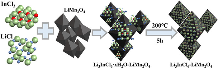
Figure 1.
Schematic illustration of the fabrication process of LIC-LMO.
Surface modification of Li3InCl6 provides superior electrochemical performance for LiMn2O4 cathode materials
Yixun Gu , Kuan Yang , Hongbin Yao , Weijian Li , Haiqing Zhan , Xianquan Ming , Guanhan Huang , Guiliang Li , Feng Zhan

Environmental problems are the biggest problems facing this century. With the continuous growth of the global population and the continuous improvement of industrialization, various countries have an increasing demand for fossil energy. Countries are still dominated by fossil energy sources, so countries need to balance fossil energy use with environmental pressures, which is not only a worldwide scientific and environmental issue but also an important development issue [1]. From this perspective, the development of energy technology will play important role in the sustainable development of the world environment. In the past decade, people have recognized the significant changes brought by new energy technology to social development. More and more power equipment is used in our life. Lithium ion battery products have become a necessity of our life and play an important role in the fields of electronics, traffic tools and aerospace [2].
In recent years, lithium-ion batteries have become more and more widely used. Among all energy storage materials, lithium-ion battery is undoubtedly one of the most potential materials, so it has been widely studied and used as the most likely energy storage material in the future. In the development process of lithium-ion batteries, the only factor that is limited is that the raw materials of lithium-ion batteries are relatively expensive, and the prices of elements such as Li, Mn and Ni are also becoming more and more expensive with the development of the new energy industry. Various different types of battery materials also play an advantage in their respective fields [3,4].
LiMn2O4 (LMO) is the most commonly used cathode material in lithium-ion batteries. With the increasing demand of human activities for LMO materials, researchers not only study the modification of LMO, but also study how to better recover LMO from waste batteries [5,6]. The main differences between LMO and other lithium-ion battery materials are low production cost, simple preparation process and easy recycling. Although LMO has the above advantages, the disadvantages are more obvious for batteries. LMO materials will have more capacity loss and lower capacity retention under high voltage (> 4.1 V), high temperature (> 50 ℃) and many cycles. These are the challenges we face. The optimization methods usually used by researchers are surface modification [7] and doping [8-10], and the optimized materials will obtain higher cycle performance or discharge specific capacity. As an excellent conductive material, Li3InCl6 (LIC) can be well used in batteries [11-13]. The above research indicates that surface modification of LMO with LIC is a relatively good way to improve the performance of batteries, so as to enhance the structural stability of LMO and improve the electrochemical performance of materials.
The development of battery technology mainly revolves around two points: capacity and cycle stability. In current research in the field, most of them adopt the method of modified materials to improve these two aspects [14]. Here, we used a simple liquid-phase synthetic cladding method. Based on this method, the LMO samples were modified by cladding using LIC. The LMO powder was prepared using a general solid-phase method. Then LIC was coated on the surface of LMO samples using aqueous phase synthesis to obtain LIC-LMO composites. In the present work, we used aqueous phase synthesis of LIC for surface modification of the cathode material LMO. In line with the direction of scientific research on lithium-ion batteries, the process of our technique was relatively simple and fast. After surface modification of LMO with LIC, the original spinel structure of LMO structure was not damaged. The synthesized material was characterized by X-ray diffraction (XRD, 10°~80°) and scanning electron microscopy (SEM). Electrochemical tests were performed on the pristine LMO and the 2 wt% modified LMO.
Commercial LMO sample (CS-LMO) is produced by Hunan Shanshan New Energy. Other chemicals are produced by Adams-beta. All samples are analytical grade.
MnO2 and Li2CO3 were used, and the two were mixed in a molar ratio of 4:1.05. Then put it into the ball mill to grind at 250 rpm for 4 h. The ground sample was warmed up to 520 ℃ at a rate of 5 ℃/min and held for 8 h. Then it was warmed up to 750 ℃ at a rate of 5 ℃/min and held for 14 h. Obtain self-prepared LMO (SP-LMO) powder. The above SP-LMO powder was dispersed in ethanol (99% purity) solution and then heated and dried under constant magnetic stirring. The fine powder of SP-LMO material was obtained after grinding in an agate mortar.
The fine powder of the SP-LMO material prepared above was dissolved in an appropriate amount of deionized water. Added the appropriate amount of LiCl solution, stirred magnetically for several minutes and then added 1/3 of the molar amount of LiCl with the same concentration of InCl3 solution (add slowly using a peristaltic pump), stirred at room temperature until uniformly dispersed, and then continued to stir until dry. The powder was placed directly in a vacuum oven without grinding and heated under vacuum at 200 ℃ for 5 h [13]. A simple synthesis method is shown in Fig. 1. The CS-LMO and SP-LMO modified by LIC surface were named as LIC-CS-LMO and LIC-SP-LMO.
The samples were characterized by X-ray diffraction (XRD) (D/ MAX 2500V, Rigaku) with Cu Kα. The morphology of particles was investigated with SEM (Sigma 300, Zeiss).
The positive electrode material was prepared by mixing the active material, acetylene black and PVDF in a mass ratio of 8:1:1, using a lithium sheet as the counter electrode separated by a porous propylene membrane (celgard2500), in a dry glove box filled with high-purity argon gas Assemble the CR2025 coin cell battery in. The positive electrode was dried under vacuum at 120 ℃ for 12 h. Each cell was tested in a potential range of 3.0-4.3 V at room temperature using a battery testing system (BTS-5V10mA, Shenzhen Neware) and an electrochemical workstation (CHI760E, CH Instruments Ins).
Fig. 2a shows the XRD diffraction patterns of LIC sample. LIC samples are prepared using the surface modification procedure described above. No impurity peaks are observed in XRD pattern and the peaks of the LIC sample were consistent with the PDF#70-3274 spectrum. This also proves that LIC with better purity can be prepared under the above conditions.
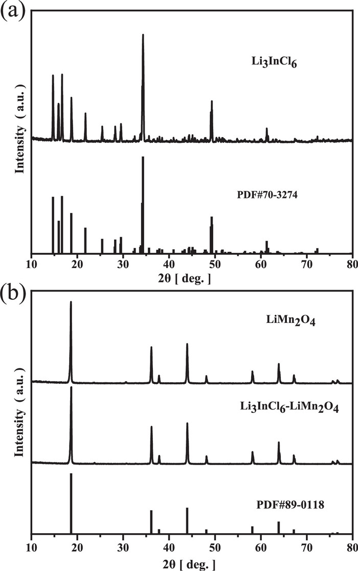
Fig. 2b shows the XRD diffraction patterns of SP-LMO sample prepared using electrolytic MnO2 and Li2CO3 and the LIC-LMO with LIC surface modification. The peaks of the LIC-LMO sample were very consistent with the PDF#89-0118 spectrum. The XRD pattern shows ten characteristic peaks located at the following positions: 18.640°, 36.131°, 37.797°, 43.925°, 48.103°, 58.135°, 63.864°, 67.167°, 75.631° and 76.663°, corresponding to (111), (311), (222), (400), (331), (511), (440), (531), (533) and (622) planes. Their positions are characteristic of the cubic spinel crystal structure, with the Fd3m space group. Matches well the standard values for LMO. Expectedly, the crystal structure of all LMO samples did not change after modification with LIC.
Figs. 3a-f show the SP-LMO and LIC-SP-LMO SEM images at different magnifications. Figs. 3a-c show the SEM images of the SP-LMO samples, which clearly shows that the octahedral structure of LMO crystal is complete. Figs. 3d–f show the SEM images of the LIC-SP-LMO samples. The size of a single particle before and after modification is about 500 nm, which proves that the method of water-phase modification has no effect on the grain size. The grain morphology of the modified LMO remained almost unchanged, but after the addition of LIC, new features could be clearly observed in the SEM image (the LIC structure was evenly distributed on the surface of the LMO material).
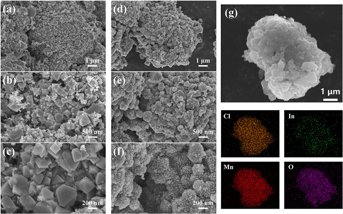
Fig. 3g is the EDS image of 2 wt% LIC-SP-LMO. EDS analysis of manganese (Mn), oxygen (O), indium (In), and chlorine (Cl) elements was performed on the 2 wt% LIC-modified LMO sample to confirm that the LIC material is uniformly distributed on the LMO material. As a result, as shown in Fig. 3g, the LIC modified layer uniformly covers the LMO particles.
The above-mentioned SP-LMO, 2% LIC-SP-LMO, CS-LMO and 2% LIC-CS-LMO were selected for electrochemical tests. Fig. 4a shows the initial charge-discharge profiles of the four materials. The discharge specific capacities of CS-LMO, SP-LMO, LIC-CS-LMO and LIC-SP-LMO are 124.7, 125.7, 128.3 and 127.8 mAh/g, respectively, during the first charge-discharge process at a rate of 0.1 C. This is four sets of similar data in LMO cells, which proves that the modification of LIC does not lead to the improvement of the specific capacity of LMO materials. During the charge-discharge process of the studied cells, two pairs of plateaus appeared at voltages around 4.1–4.2 V and 3.9–4.1 V, which correspond to the redox process of LMO and are characteristic of LMO.
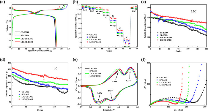
Fig. 4b shows the rate capability of SP-LMO, LIC-SP-LMO, CS-LMO and LIC-CS-LMO in the voltage range of 3.0-4.3 V. The results show that the performance of the modified material is significantly improved compared to the pure phase. For example, the discharge specific capacities of CS-LMO, SP-LMO, LIC-CS-LMO and LIC-SP-LMO are 68, 83, 79 and 91 mAh/g at 2 C. LIC-CS-LMO is 15% higher than CS-LMO. LIC-SP-LMO is 10% higher than SP-LMO. The discharge specific capacity of the LMO material modified by LIC is obviously higher than that of the other two samples.
Fig. 4c shows the cycling performance of the four samples at 0.5 C. After the 150th cycle, the discharge specific capacities of CS-LMO, SP-LMO, LIC-CS-LMO and LIC-CS-LMO were 101.8, 105.3, 107.8 and 114.4 mAh/g. The capacity retention rates of the four samples were 84.9%, 83.7%, 89.8% and 90.0%, respectively. Fig. 4d shows the cycling performance of the three samples at 1 C. After the 200th cycle, the discharge specific capacities of CS-LMO, SP-LMO, LIC-CS-LMO and LIC-SP-LMO were 85.9, 90.6, 96.6 and 103.5 mAh/g. The capacity retention rates of the four samples were 78.7%, 78.8%, 85.6% and 85.0%, respectively. It can be seen from Figs. 4c and d that the modification of LMO by LIC can significantly improve the cycling performance of LMO. This is due to the fact that the addition of LIC makes the microscopic morphology of LMO well maintained during the charging and discharging process of the LMO material. At both 0.5 C and 1 C, the cycling performance is improved by more than 6%.
Fig. 4e shows the cyclic voltammetry curves of each group. Due to the intercalation/deintercalation of lithium ions, two pairs of redox peaks will be generated (3.87/4.11 V and 4.03/4.22 V), which correspond to the deintercalation processes of two Li+ of LMO materials, which are the characteristics of LMO materials. We can see that there is no significant difference (obvious deviation) in the voltage of the four curves, so we think that the surface modification of LIC does not hinder the charging and discharging process of LMO, which also corresponds to Fig. 1a.
Fig. 4f shows the impedance spectra of the four samples. By comparison, the sample modified by LIC surface in the figure is obviously superior to the other two samples. This is due to the faster charge transfer on the surface of the LMO material due to the modification of LIC, which leads to its better electrochemical performance.
In conclusion, the LMO material after LIC surface modification shows more excellent cycling performance. It is demonstrated that the surface modification of LIC improves the cycling stability of LMO. During the charging and discharging process, the surface coating of LIC can reduce the morphology change of LMO and maintain the basic spinel structure, thus effectively improving the electrochemical performance of the material.
In this work, we used a simple wet-chemical synthesis method for surface modification of LMO particles using LIC. The XRD results show that the modified LMO still has a spinel structure with the Fd3m space group. After LIC surface modification, the LMO structure remained intact. Electrochemical characterization was performed using a CR2025 coin cell configuration. After 150 cycles at 0.5 C rate, the capacity retention of 2 wt% LIC-LMO is about 6% higher than that of CS-LMO sample. After 200 cycles at 1 C rate, the capacity retention of 2 wt% LIC-LMO is about 6.5% higher than that of the LMO sample. This is because LIC has high ionic conductivity (10−3 to 10−4 S/cm) and good electrochemical stability, so it can keep the morphology of LMO sample well during the cycle [11-13]. We also compared our experiments with those of others before us [7]. The experimental steps of the aqueous phase method adopted by us are much simpler than theirs, but the cycling performance of our sample is 2.5% higher than theirs. This is good news for the development of LMOs. In the future, it is planned to optimize the preparation process of this series of samples for surface modification of LMO by solid-phase method. It is expected to achieve large-scale application in industrial production while maintaining high cycle performance.
The authors declare that they have no known competing financial interests or personal relationships that could have appeared to influence the work reported in this paper.
This work was supported by Guangxi Higher Education Key Laboratory of Advanced Materials, Center of Ecological Collaborative Innovation for Aluminum Industry in Guangxi, CITIC Dameng Mining Industries Limited-Guangxi University Joint Research Institute of Manganese Resources Utilization and Advanced Materials Technology, Guangxi University-CITIC Dameng Mining Industries Limited Joint Base of Postgraduate Cultivation, National Natural Science Foundation of China (No. 11364003), Guangxi Innovation Driven Development Project (Nos. AA17204100, AA18118052), the Natural Science Foundation of Guangxi Province (No. 2018GXNSFAA138186).
B. Novotnik, A. Nandy, S.V. Venkatesan, et al., Rev. Environ. Sci. Bio. 19 (2020) 217-240. doi: 10.1007/s11157-020-09527-z
V. Etacheri, R. Marom, R. Elazari, et al., Energy Environ. Sci. 4 (2011) 3243-3262. doi: 10.1039/c1ee01598b
H. Wang, Q. Gao, C. Liu, et al., Chin. Chem. Lett. 33 (2022) 3842-3848. doi: 10.1016/j.cclet.2021.11.030
N. T. Aristote, K. Zou, A. Di, et al., Chin. Chem. Lett. 33 (2022) 730-742. doi: 10.1016/j.cclet.2021.08.049
H. Gao, Q. Yan, P. Xu, et al., ACS Appl. Mater. Interfaces 12 (2020) 51546-51554. doi: 10.1021/acsami.0c15704
L. Yao, Y. Xi, H. Han, et al., J. Alloys Compd. 868 (2021) 159222. doi: 10.1016/j.jallcom.2021.159222
M. Michalska, D.A. Buchberger, J.B. Jasinski, et al., Materials 14 (2021) 4134. doi: 10.3390/ma14154134
K. Chudzik, M. Świętosławski, M. Bakierska, et al., Electrochim. Acta 373 (2021) 137901. doi: 10.1016/j.electacta.2021.137901
K. Chudzik, M. Świętosławski, M. Bakierska, et al., Appl. Surf. Sci. 531 (2020) 147138. doi: 10.1016/j.apsusc.2020.147138
R. Tabassam, F. Alvi, N. Aslam, et al., Mater. Lett. 302 (2021) 130275. doi: 10.1016/j.matlet.2021.130275
Y. Zhang, C. Sun, ACS Appl Mater Interfaces 13 (2021) 12099-12105. doi: 10.1021/acsami.1c00745
J. Kim, S. S. Shin, J. Lee, et al., Appl. Surf. Sci. 574 (2022) 151621. doi: 10.1016/j.apsusc.2021.151621
X. Li, J. Liang, N. Chen, et al., Angew. Chem. Int. Ed. 58 (2019) 16427-16432. doi: 10.1002/anie.201909805
J. Lu, C. Zhan, T. Wu, et al., Nat. Commun. 5 (2014) 1-8. doi: 10.1155/2014/414613

Figure 2 (a) XRD diffraction patterns of Li3InCl6. (b) XRD diffraction patterns of LiMn2O4 and Li3InCl6-LiMn2O4.

Figure 3 (a-c) The SEM images of LMO. (d-f) The SEM images of 2 wt% LIC-LMO. (g) The EDS images of 2 wt% LIC-SP-LMO.

 扫一扫看文章

扫一扫关注我们
 DownLoad:

 下载:
下载:
