Table 1.
Particle size of graphite with different meshes.
Citation:
Junsheng Zheng, Yuhang Peng, Runlin Fan, Jing Chen, Zize Zhan, Dongmei Yao, Pingwen Ming. Study on carbon matrix composite bipolar plates with balance of conductivity and flexural strength[J]. Chinese Chemical Letters,
2023, 34(5): 107616.
doi:
10.1016/j.cclet.2022.06.039

Study on carbon matrix composite bipolar plates with balance of conductivity and flexural strength
English
Study on carbon matrix composite bipolar plates with balance of conductivity and flexural strength
Abstract:
In order to balance the conductivity and flexural strength of graphite composite bipolar plates, the influence of conductive filler on the properties of graphite composite bipolar plate was comprehensively studied by using phenolic resin as binder, natural flake graphite as conductive substrate and functional carbon materials with different structures as auxiliary filler. The results show that the particle size of conductive substrate has an important influence on the conductivity enhancement of auxiliary filler. The influence of conductive particle size on auxiliary filler electrical conductivity improvement was first investigated in this research. The effects of various auxiliary filler concentrations on improving electrical conductivity and flexural strength were then examined. This research has substantial implications for the balance of electrical conductivity and flexural strength of graphite composite bipolar plates.
-
The proton exchange membrane fuel cell (PEMFC) has been identified as a potential power system due to its noticeable advantages such as high power density and efficiency (>55%), quick response to power consumption, and few environmental contaminants emission [1,2]. At present, one of the important issues restricting the promotion and application of hydrogen fuel cell vehicles is that the manufacturing cost of fuel cell is difficult to reduce, among which precious metal catalysts and bipolar plate components account for a large proportion of the total cost. Therefore, non-platinum catalysts and reducing the production cost of bipolar plate are important aspects to promote fuel cell vehicles. Non-metal doped carbon materials and transition metal compounds are widely studied to replace platinum-based catalysts to reduce costs [3-5].
Composite material is a new type of materials for the preparation of fuel cell bipolar plate which use polymer resin as binder and carbon material as conductive filler. Polymer is the basis to ensure the air tightness and flexural strength of composite bipolar plate [6-8]. Thermosetting resin and conductive filler can be uniformly dispersed through dry mixing or wet mixing, and then the fuel cell bipolar plate can be formed by hot molding process. Thermosetting resin has the characteristics of low viscosity and can form a good interface combination with carbon based fillers under high packing concentration. For bipolar plate materials, it can form a uniform distribution phase with filler to achieve ideal electrical conductivity and flexural strength [6,9-12].
Dueramae et al. prepared polybenzoxazine composites with high graphite-loaded content [13], and found that gaps may exist in the composites due to the lack of wetting ability of the polymer at high packing concentration. The particle size of the conductive filler determines the morphology of the three-dimensional network structure formed by the polymer resin. The smaller the particle size of graphite is, the more complex the three-dimensional network structure forms, and the higher the flexural strength of the composite material is [14-16]. However, as the graphite particle size decreases, the graphite particles are isolated by insulating polymers, and the contact resistance between conductive fillers increases, leading to the reduction of the conductivity of composite bipolar plate [17]. Studies have found that the contact between graphite particles can be increased and the conductivity of composite plate can be enhanced by matching graphite particles with different particle sizes [18,19].
Using highly conductive nanoparticle materials and fibrous carbon materials with high tensile strength and high aspect ratio as auxiliary fillers can form conductive contacts and strength bridges between graphite particles, achieving the effect of significantly improving the conductivity and flexural strength. However, uniform dispersion is important for the auxiliary filler to fully functioning. Compared with direct mechanical stirring or melt blending, the wet mixing method combined with mechanical stirring can achieve the ideal dispersion uniformity [20-22].
Carbon black can fill in the gap of expanded graphite, establish a large number of electronic conductive pathways, and achieve the conductive synergistic effect with expanded graphite [23,24]. Carbon black is more difficult to be wetted by resin due to its high specific surface area. When the concentration of carbon black exceeds a certain limit, the conductivity of the composite electrode plate will decrease. The reason for this phenomenon is that the carbon black of high concentration would agglomerate within the composite, resulting in a substantial reduction in flexural strength [25,26].
In graphite composites, multi-walled carbon nanotubes (MWCNT) can be filled between graphite particles to improve the conductive and thermal contact of graphite composites. Carbon nanotubes have the characteristics of high aspect ratio, tensile strength and flexibility. The dispersion of carbon nanotubes into polymers can significantly improve the tensile properties of composites [27]. The main problem of carbon nanotubes as auxiliary fillers is that, as materials with a high aspect ratio, carbon nanotubes are prone to agglomeration. When carbon nanotubes are saturated in the composite, the agglomeration of it reduces the effect of improving the conductivity and thermal conductivity and flexural strength [28-31].
Ghosh et al. added carbon fibers of different lengths into graphite-phenolic composite plates as the second filler to study the influence of carbon fiber lengths on the performance of conductive composite materials [32]. The 1 mm length of carbon fiber has the most obvious enhancement effect on the composite plate, and the electrical conductivity of the composite material is improved to a certain extent. With the further increase of carbon fiber length, the agglomeration of carbon fiber tended to occur, resulting in uneven distribution in the composite, and the strengthening effect of carbon fiber decreased gradually.
Previous research on auxiliary fillers was limited to the effect of auxiliary fillers on the properties of graphite composite sheets. In order to obtain better comprehensive performance, the influence of graphite particle size on the conductivity of auxiliary filler was firstly studied in this paper. The change law of the properties of the graphite composite plate with the concentration of the auxiliary filler was further analyzed, and the purpose of balancing the electrical conductivity and the flexural strength was finally achieved.
Anhydrous ethanol (AR, 99.5%) was purchased from Sinopharm Group Co., Ltd. Water soluble phenolic resin (70% solid content) purchased from Vokai reagent Co., Ltd. Natural flake graphite from Qingdao Nanshu Graphite Co., Ltd. Conductive carbon black is purchased from Xianfeng Nano Co., Ltd. Cut carbon fiber (1 mm) and multi-walled carbon nanotubes (7–15 µm, 5–15 nm) were purchased from Nakamori Pilot Co., Ltd.
Firstly, the calculated amount of phenolic resin was weighed and dissolved in absolute ethanol solvent. Stir and sonicate for 10 min to obtain a homogeneous phenolic resin solution. Then, a fixed proportion of flake graphite powder was added, and the fluid slurry was mechanically stirred at a speed of 500 r/min for 30 min, and then dried at a constant temperature of 60 ℃ in a blast drying oven for 2 h to completely remove the solvent. The dried samples were pulverized in a mechanical pulverizer for 1 min to serve as a masterbatch for thermoforming.
Due to the high specific surface area and polar surface of conductive carbon black, carbon nanotubes and cut carbon fibers, ultrasonic treatment, mechanical agitation and mechanical crushing were used for different auxiliary fillers in this paper. When carbon black (CB) was used as the auxiliary filler, it was dispersed separately into the resin solution firstly, and then treated by mechanical stirring at 500 r/min speed for 10 min after 30 min of ultrasonic treatment. The flake graphite powder was then added. When carbon nanotubes were used as the auxiliary filler, they were first added into the resin solution after ultrasonic dissolution for 30 min, so that the dispersed carbon nanotubes were dispersed into a relatively thick slurry. When the short-cut carbon fiber was used as the auxiliary filler, the short-cut carbon fiber bundle was first crushed in a mechanical grinder for 2 min to make it untangled and bonded.
Graphite composite bipolar plate was prepared by hot molding. The base material was uniformly filled into the mold and pressed to 30 MPa at a pressure rate of 5 MPa/min at room temperature. Then the mold was heated to 170 ℃ and kept constant temperature and pressure for 30 min to make the resin completely solidified, that is, the graphite composite plate prepared.
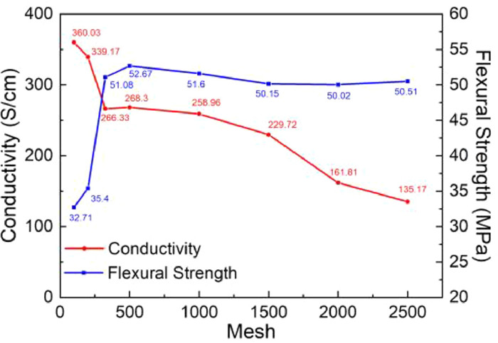
Graphite composite plates were prepared from flake graphite with different particle sizes, and the relationship between the internal structure of plate and its electrical conductivity and flexural strength was discussed. The selected scale graphite mesh numbers include 100 mesh, 200 mesh, 325 mesh, 500 mesh, 1000 mesh, 1500 mesh, 2000 mesh and 2500 mesh. The particle sizes of graphite with different mesh numbers are shown in Table 1. As shown in Fig. 1, as the graphite particle size becomes smaller and smaller, the conductivity declines rapidly at first, then appears a relatively stable platform, and finally slowly declines. When the particle size of graphite decreases from 100 mesh to 325 mesh, the conductivity decreases rapidly from 360.03 S/cm to 266.33 S/cm. The decrease of graphite particle size leads to an increase in the number of graphite particles per unit volume and the number of graphite particles along any conductive path. The graphite is bonded together by non-conductive resin at the contact node to form a transition phase with poor electrical conductivity. Macroscopically, the increase of contact nodes shows that the in-plane conductivity of graphite composite plate decreases rapidly.
Table 1
Figure 1
 Figure 1. Variation of electrical conductivity and flexural strength with graphite particle size.
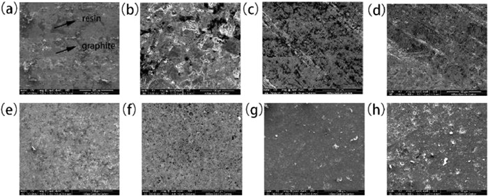
In the range of graphite particle sizes from 325 mesh to 1000 mesh, the in-plane conductivity of the graphite composite shows a stable plateau around 260 S/cm. In this particle size range, the bulk density of graphite particles increases and more conductive paths are formed. Graphite has good electrical conductivity and is the light colored area in SEM images. The dark area in SEM image is resin insulating phase. As shown in Figs. 2a-d, the resin-filled large-area pores between graphite particles gradually decrease. The internal conductive paths of graphite composites gradually increase, which makes the macroscopic in-plane conductivity increase. However, the number of contact points formed by graphite coated by resin on any conductive path increases, resulting in a downward trend of the macroscopic in-plane conductivity. In the particle size range from 325 mesh to 1000 mesh, the in-plane conductivity of the composite plate is in dynamic equilibrium.
Figure 2
 Figure 2. SEM images of the surface of graphite composite plates with different particle sizes: (a) 100 mesh, (b) 200 mesh, (c) 325 mesh, (d) 500 mesh, (e) 1000 mesh, (f) 1500 mesh, (g) 2000 mesh, (h) 2500 mesh.
As the graphite particles further shrink from 1000 mesh, the accumulation of graphite particles reaches a certain degree of saturation, and no obvious pores are observed between the graphite particles, as shown in Figs. 2d-h. The increase of the number of conductive paths on the in-plane conductivity of graphite composites is not enough to offset the decline of the in-plane conductivity of graphite composites with the raise of contact points on any conductive path. The in-plane conductivity of graphite composites continues to drop.
The flexural strength of graphite composites increases rapidly at first and then maintains a trend of equilibrium when the particle sizes of graphite vary from 100 mesh to 2500 mesh as Fig. 1 shows. When the graphite particle size decreases from 100 mesh to 325 mesh, the flexural strength increases rapidly from 32.71 MPa to 51.08 MPa. When the particle size of graphite continues to decrease in the range of 325 mesh to 2500 mesh, the flexural strength of graphite composites remains balanced in the range of 50.02 MPa to 52.67 MPa. As shown in Figs. 2a and b, when the particle size of graphite decreases from 100 mesh to 325 mesh, the holes among graphite particles narrow and the distribution of resin in graphite composite plate becomes more uniform, so the flexural strength increases rapidly. When the particle size of graphite is further reduced, the bonding area between graphite particles increases. The resin layer coated with graphite particles becomes thinner and the bonding strength between graphite particles decreases. The strength of graphite composite plate is stable due to the bonding strength of resin itself.
The size of the graphite particle size affects the gap size of the graphite stack to a large extent. Nano conductive additives such as carbon black form conductive connections by connecting different graphite particles in the gaps of graphite particles. Therefore, there is a certain correlation between the size of the gaps between graphite particles and the enhancement effect of conductive additives.
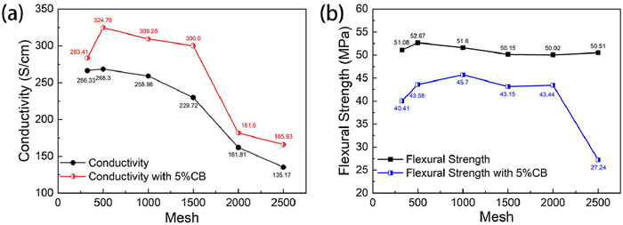
Fig. 3a shows the variation of the conductivity of the graphite composite plate with the addition of 5% conductive carbon black. After adding the conductive auxiliary filler with a concentration of 5%, the composite plate has a certain improvement. Fig. 4 shows the distribution of conductive carbon black in the graphite composite plate. The distribution of carbon black in the gaps of graphite particles is beneficial to increasing conductive contacts. When the graphite particle size is 500 mesh, 1000 mesh, and 1500 mesh, the conductive additive shows a more obvious conductive enhancement effect. It can be seen that the particle size of the conductive substrate has an important influence on the conductive additive. If the graphite particle size is larger, the pores between the graphite particles are larger, resulting in poor dispersion of the conductive additives. A large amount of carbon black accumulates in the pores among graphite particles, resulting in the inability to form enough conductive paths between graphite gaps. On the other hand, the gap between the bonding surfaces of the graphite particles is larger, carbon black with small particle size does not form effective conductive bridges in large gaps. Therefore, when the 325 mesh graphite is added with highly conductive carbon black as the conductive additive, the conductivity of the graphite composite plate is increased less. When the graphite with particle size of 500 mesh to 1500 mesh is applied, the electrical conductivity can be increased around 50–70 S/cm. Within this particle size range, the carbon black can be more uniformly dispersed in the contact gap of the graphite, and carbon black is more likely to form conductive bridges between the smaller graphite gaps to increase the conductive path of the composite material. When the graphite particle size is further reduced, the difference between the size of the carbon black and the flake graphite particles is reduced, and the carbon black cannot be filled well in the gaps of the flake graphite, destroying the stacking orientation of the graphite particles, so that the conductivity enhancement effect at 2000 mesh and at 2500 mesh graphite becomes poor.
Figure 3
 Figure 3. Variation of properties of composite plate with 5% concentration of conductive carbon black additive with different graphite particle size. (a) conductivity, (b) flexural strength.
Figure 4
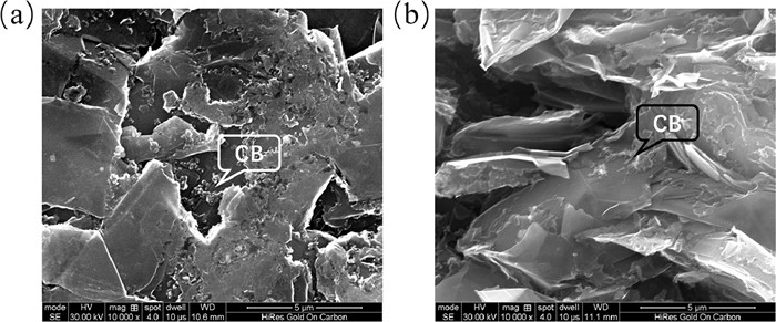
 Figure 4. Distribution of conductive carbon black in graphite composite plates. (a) surface, (b) section.
As shown in Fig. 3b, with the incorporation of carbon black as an auxiliary filler, the flexural strength of graphite composite plates with all particle sizes decrease observably. In the particle size range of 325 mesh to 2000 mesh, the flexural strength of composite plate with carbon black additive appears the best performance at 1000 mesh, but the overall change with particle size is not big, in a relatively stable trend. And the flexural strength decreases sharply when the graphite particle size is 2500 mesh. Conductive carbon black is a spherical nano-carbon material with a size of 40–50 nm. It has the characteristics of high specific surface area. When carbon black is dispersed as a filler phase between the graphite particles, with the specific surface area of the filler increasing, more resin coating is required to form the bonding interface. As a result, the interface bonding strength is reduced, so when carbon black is used as an auxiliary filler, the overall flexural strength of the graphite composite plates is reduced to a certain extent. When the specific surface area of the filler including graphite and carbon black exceeds the coating capacity of 20% of the resin concentration, the composite plates exhibit the brittleness of the carbon material. Therefore, after adding conductive carbon black to 2500 mesh flake graphite, the flexural strength of the graphite composite plate is only half of the original.
Analysis of the effect of flake graphite particle size on the electrical conductivity and flexural strength of the composite plates with auxiliary fillers shows that natural flake graphite with a particle size of 1000 meshes as the conductive substrate has the most balanced electrical conductivity and flexural strength after adding conductive carbon black.
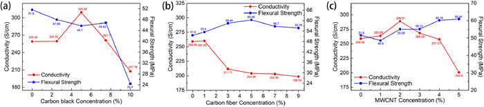
The composite plates with different conductive carbon black concentrations were prepared under the condition that the total filler concentration was kept at 80%. And the mesh of graphite particle is 1000. Fig. 5a shows the variation of electrical conductivity and flexural strength with carbon black concentration. It can be seen that with the increase of carbon black concentration, the electrical conductivity of the graphite composite plate shows a trend of increasing first and then decreasing rapidly. When the concentration of carbon black is 5%, the conductivity is 309.28 S/cm, showing the best conductivity enhancement effect. With the further increase of the concentration, the electrical conductivity decreased rapidly, and dropped to 207.76 S/cm when the concentration of 10% carbon black was added, which was 51.2 S/cm, lower than that when no carbon black was added. It shows that when the concentration of carbon black is within 5%, the carbon black can be filled between the graphite gaps with an ideal degree of dispersion, and more conductive paths are formed between the graphite particles, thereby increasing the electrical conductivity of the graphite composite plate. The reason why the conductivity showed a rapid decrease trend is that the agglomeration of carbon black disables the carbon black to well disperse in the graphite gap to promote the formation of conductive paths. At the same time, the conductivity of carbon black is inferior to that of flake graphite, and the decrease in the proportion of graphite also leads to a decrease in the conductivity of the graphite composite plate.
Figure 5
 Figure 5. Variation of properties of graphite composite plates with the concentration of conductive additives. (a) carbon black, (b) carbon fiber, (c) MWCNT.
With the addition of conductive carbon black, the flexural strength of the graphite composite plate firstly decreases slowly, and when the concentration of carbon black is 10%, the flexural strength greatly decreases to 24.4 MPa. The high porosity and high specific surface area of conductive carbon black make conductive carbon black require more resin coating than graphite particles to form a stable bond between particles. When the carbon black is dispersed between the graphite gaps, the bonding strength between the fillers is reduced, so the flexural strength gradually decreases. When the concentration of carbon black is about 10%, the overall specific surface area of graphite and carbon black exceeds the coating ability of the resin with a concentration of 20%, and high-strength bonding cannot be formed between filler particle, so the flexural strength is greatly reduced.
In conclusion, 5% concentration of carbon black is the maximum concentration that can achieve good dispersion performance in graphite composite plate. At this concentration, graphite composite plate shows the best enhancement effect on conductance and small reduction of flexural strength.
Chopped carbon fibers with a length of 1 mm were used as auxiliary fillers. The changes in electrical conductivity and flexural strength of graphite composite plates were investigated at 1%, 3%, 5%, 7% and 9% carbon fiber addition concentrations. As shown in Fig. 5b, the addition of chopped carbon fibers reduces the electrical conductivity of the graphite composite plates. There was a sharp decrease in conductivity between 1% and 3% addition concentration, and after 3% concentration, the conductivity decreased slowly with a small deceleration as the addition concentration continued to increase. The main reason for the sharp decrease in electrical conductivity at 3% may be that the incorporation of carbon fibers destroys the graphite and causes the ordered arrangement of graphite sheets parallel to the surface of the composite plate. Graphite is a multilayer structure composed of graphene, which has better electrical conductivity parallel to the direction of the graphene sheet. Therefore, the composite plate with parallel graphite layer has better in-plane conductivity.
The flexural strength of composite bipolar plates can be improved obviously with the addition of chopped carbon fiber. With the increase of the concentration, the flexural strength increases first and then decreases slowly after reaching the maximum. In this case, the flexural strength of graphite composite plate is 60.46 MPa which is 8.86 MPa higher than that of pure graphite composite plate. The inflection point at the 5% concentration indicates that when the carbon fiber concentration is greater than 5%, agglomeration occurs in the graphite composite plate and the dispersion becomes worse.
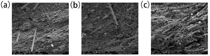
Fig. 6 shows the SEM images of the sections of composite plates with chopped carbon fiber at 3%, 5% and 7% concentrations. It can be seen that the carbon fiber is pulled out from the composite material at the section, alleviating the brittle fracture of the graphite composite plate during flexural, which proves that the high tensile strength of carbon fiber improves the flexural performance of the composite plate. When the concentration is 3%, the carbon fiber is scattered in the composite. When the concentration is 5%, an obvious amount of carbon fiber can be observed to disperse evenly among the graphite particles to form reinforcing phase. At a concentration of 7%, a large number of carbon fiber monomers can be observed to aggregate into fiber bundles. It shows that when the concentration of chopped carbon fiber is more than 5%, it is difficult to separate the high concentration of chopped carbon fiber. Because of the high polar surface of carbon fiber, which aggregates into fiber bundles and agglomerates inside the composite plate, it is difficult to form a uniformly distributed reinforcement phase, resulting in uneven distribution of mechanical properties of the composite plate.
Figure 6
 Figure 6. SEM images of section of composite plates with different carbon fiber concentrations. (a) 3%, (b) 5%, (c) 7%.
The changes of electrical conductivity and flexural strength of composite plates under different MWCNT concentration gradients were investigated with MWCNTs added at 1%, 2%, 3%, 4% and 5%. As shown in Fig. 5c, with the increase of the concentration of MWCNTs, the electrical conductivity had a trend of increasing first and then decreasing. When the added concentration was 2%, the conductivity curve appeared a peak. The electrical conductivity at this time is 289.01 S/cm, which shows a more obvious conductivity enhancement effect than that of the pristine graphite composite plate. As the concentration increases further, the conductivity begins to decrease. And it is 200.8 S/cm at 5% concentration, which is much smaller than the graphite composite plate without addition. The conductivity decreased after the addition of 2% concentration. The reason is that when the carbon nanotubes increase to a certain concentration, they are more likely to agglomerate, and the unevenly dispersed multi-walled carbon nanotubes cannot achieve the good expectation of increasing the conductive path.
The flexural strength of the graphite composite plate showed a gradual upward trend as a whole with the increase of the concentration of multi-walled carbon nanotubes. The flexural strength at the inflection point of the conductivity curve increases to 55.08 MPa, which is a certain improvement compared to the unadded graphite composite plate. When the concentration of multi-walled carbon nanotubes was further increased, the flexural strength showed a gradual upward trend, reaching 60.94 MPa at 5% concentration. Multi-walled carbon nanotubes, as nano-scale fibrous materials, are beneficial to improve the toughness and strength of the polymer when filled in the resin. The discrete extension of carbon nanotubes in the resin can significantly enhance the mechanical properties of the graphite composite plates.
The graphite composite plate at 2% concentration has the best comprehensive performance, with high conductivity of 289.01 S/cm and flexural strength of 55.08 MPa. Further increasing the MWCNT concentration can effectively improve the flexural strength of graphite composite plate.
In this paper, based on the study of the enhancement and conductivity of graphite particle size of graphite composite plate to the auxiliary filler, a comprehensive study of the conductive filler of graphite composite plate has been done, which is of great significance to balancing the conductivity and flexural strength of graphite composite plate. At graphite particle size of 325–1000 mesh, the composite graphite plate has relatively balanced electrical conductivity and flexural strength. The auxiliary filler has better conductance enhancement and strengthening effect on 1000 mesh flake graphite composite plate. The high conductivity of 309.28 S/cm and flexural strength of 60.94 MPa were obtained by 1000 mesh flake graphite with different auxiliary fillers.
Declaration of competing interest
The authors declare that they have no known competing financial interests or personal relationships that could have appeared to influence the work reported in this paper.
Acknowledgment
The authors would like to acknowledge the financial supports from the National Key R&D Program of China (Nos. 2020YFB1505904 and 2018YFB1502502–04).
-
-
[1]
V.M. Vishnyakov, Vacuum 80 (2006) 1053–1065. doi: 10.1016/j.vacuum.2006.03.029
-
[2]
Y. Liu, Z. Yu, J. Chen, et al., Chin. Chem. Lett. 33 (2022) 1817–1830. doi: 10.1016/j.cclet.2021.09.023
-
[3]
L. Chen, X. Xu, W. Yang, et al., Chin. Chem. Lett. 31 (2020) 626–634. doi: 10.1016/j.cclet.2019.08.008
-
[4]
S. Yao, T. Huang, H. Fang, et al., Chin. Chem. Lett. 31 (2020) 530–534. doi: 10.1016/j.cclet.2019.04.069
-
[5]
S. Li, B. Li, L. Ma, et al., Chin. Chem. Lett. 28 (2017) 2159–2163. doi: 10.1016/j.cclet.2017.08.029
-
[6]
R.A. Antunes, M.C.L. de Oliveira, G. Ett, et al., J. Power Sources 196 (2011) 2945–2961. doi: 10.1016/j.jpowsour.2010.12.041
-
[7]
W. Zhang, A.A. Dehghanisanij, R.S. Blackburn, J. Mater. Sci. 42 (2007) 3408–3418. doi: 10.1007/s10853-007-1688-5
-
[8]
H. Deng, L. Lin, M. Ji, et al., Prog. Polym. Sci. 39 (2014) 627–655. doi: 10.1016/j.progpolymsci.2013.07.007
-
[9]
E.A. Cho, U.S. Jeon, H.Y. Ha, et al., J. Power Sources 125 (2004) 178–182. doi: 10.1016/j.jpowsour.2003.08.039
-
[10]
S. Simaafrookhteh, M. Khorshidian, M. Momenifar, Int. J. Hydrog. Energy 45 (2020) 14119–14132. doi: 10.1016/j.ijhydene.2020.03.105
-
[11]
K.C. Li, K. Zhang, G. Wu, J. Appl. Polym. Sci. 130 (2013) 2296–2302. doi: 10.1002/app.39444
-
[12]
F.G. Boyaci San, O. Okur, Int. J. Hydrog. Energy 42 (2017) 23054–23069. doi: 10.1016/j.ijhydene.2017.07.175
-
[13]
I. Dueramae, A. Pengdam, S. Rimdusit, J. Appl. Polym. Sci. (2013) 3909–3918. doi: 10.1002/app.39661
-
[14]
S.I. Heo, J.C. Yun, K.S. Oh, et al., Adv. Compos. Mater. 15 (2012) 115–126.
-
[15]
S.R. Dhakate, S. Sharma, R.B. Mathur, Carbon Lett. 14 (2013) 40–44. doi: 10.5714/CL.2012.14.1.040
-
[16]
H. Chen, H. Liu, J. Li, et al., J. Compos. Mater. 43 (2009) 755–767. doi: 10.1177/0021998308101295
-
[17]
d.Rafi ud, M. Arshad, A. Saleem, et al., J. Thermoplast. Compos. 29 (2016) 1315–1331. doi: 10.1177/0892705714563124
-
[18]
S.R. Dhakate, R.B. Mathur, S. Sharma, et al., Energ. Fuel. 23 (2009) 934–941. doi: 10.1021/ef800744m
-
[19]
C. Shen, M. Pan, R. Yuan, Int. J. Hydrog. Energy 33 (2008) 1035–1039. doi: 10.1016/j.ijhydene.2007.11.013
-
[20]
F. Roncaglia, M. Romagnoli, S. Incudini, et al., Int. J. Hydrog. Energy 46 (2021) 4407–4416. doi: 10.1016/j.ijhydene.2020.10.272
-
[21]
R. Dweiri, J. Sahari, J. Power Sources 171 (2007) 424–432. doi: 10.1016/j.jpowsour.2007.05.106
-
[22]
P. Chaiwan, J. Pumchusak, Electrochim. Acta 158 (2015) 1–6. doi: 10.1016/j.electacta.2015.01.101
-
[23]
L. Du, S.C. Jana, J. Power Sources 172 (2007) 734–741. doi: 10.1016/j.jpowsour.2007.05.088
-
[24]
A. Adloo, M. Sadeghi, M. Masoomi, et al., Renew. Energ. 99 (2016) 867–874. doi: 10.1016/j.renene.2016.07.062
-
[25]
H. Suherman, J. Sahari, A.B. Sulong, Ceram. Int. 39 (2013) 7159–7166. doi: 10.1016/j.ceramint.2013.02.059
-
[26]
M.C. Lopes de Oliveira, I.J. Sayeg, G. Ett, et al., Int. J. Hydrog. Energy 39 (2014) 16405–16418. doi: 10.1016/j.ijhydene.2014.07.175
-
[27]
J. You, J.-Y.-Q. Cao, S.-.C. Chen, et al., Chin. Chem. Lett. 28 (2017) 201–205. doi: 10.1016/j.cclet.2016.06.039
-
[28]
A. Naji, B. Krause, P. Pötschke, et al., Polym. Compos. 40 (2018) 3189–3198.
-
[29]
S.R. Dhakate, S. Sharma, N. Chauhan, et al., Int. J. Hydrog. Energy 35 (2010) 4195–4200. doi: 10.1016/j.ijhydene.2010.02.072
-
[30]
H.E. Lee, S.H. Han, S.A. Song, et al., Compos. Struct. 134 (2015) 44–51. doi: 10.1016/j.compstruct.2015.08.037
-
[31]
S. Liu, P. Wang, C. Liu, et al., Small 16 (2020) 2002856. doi: 10.1002/smll.202002856
-
[32]
A. Ghosh, P. Goswami, P. Mahanta, et al., J. Solid State Electrochem. 18 (2014) 3427–3436. doi: 10.1007/s10008-014-2573-1
-
[1]
-
Figure 1 Variation of electrical conductivity and flexural strength with graphite particle size.
Figure 2 SEM images of the surface of graphite composite plates with different particle sizes: (a) 100 mesh, (b) 200 mesh, (c) 325 mesh, (d) 500 mesh, (e) 1000 mesh, (f) 1500 mesh, (g) 2000 mesh, (h) 2500 mesh.
Figure 3 Variation of properties of composite plate with 5% concentration of conductive carbon black additive with different graphite particle size. (a) conductivity, (b) flexural strength.
Figure 4 Distribution of conductive carbon black in graphite composite plates. (a) surface, (b) section.
Figure 5 Variation of properties of graphite composite plates with the concentration of conductive additives. (a) carbon black, (b) carbon fiber, (c) MWCNT.
Figure 6 SEM images of section of composite plates with different carbon fiber concentrations. (a) 3%, (b) 5%, (c) 7%.
-

 DownLoad:


 下载:
下载:


 扫一扫看文章
计量
- PDF下载量: 8
- 文章访问数: 1188
- HTML全文浏览量: 73
