School of Environment and Energy, State Key Laboratory of Luminescent Materials and Device, Guangdong Provincial Key Laboratory of Atmospheric Environment and Pollution Control, South China University of Technology, Guangzhou 510000, China
Received Date:
09 May 2022 Accepted Date:
08 June 2022 Revised Date:
25 May 2022 Available Online:
15 May 2023
Abstract:
Stable solid-electrolyte interphase (SEI) is crucial for advanced development of lithium metal batteries. However, the continuous collapse and reconstruction of SEI will deplete fresh Li and electrolytes upon cycling, leading to irreversible capacity loss. Herein, we addressed this issue by pre-formation of artificial robust hybrid interphase on a 3D layered graphene/lithium metal framework, in which is constructed by LiF associated with Li2TiF6 generated by the in-situ reaction between the surfacial lithium and titanium fluoride contained electrolytes. The as-obtained interphase can maintain the structure integrality and avoid continuous consumption of the fresh Li and electrolytes. As a consequence, the Li symmetric cells achieve high-efficiency Li deposition and stable cycling over 3600 h. When paired with LiFePO4 cathodes, the coin cells exhibit long lifespan (> 800 cycles) with almost 88.3% retention of the initial capacity.
Lithium (Li) metal has been considered as a promising anode material for future high energy batteries in portable electronics and electric vehicles owing to its high theoretical capacity and the lowest anode potential [1-4]. In Li metal batteries, constructing stable solid-electrolyte interphase (SEI) is among the most effective strategies to prevent the Li dendrite growth and thus to improve the cycling efficiency. The SEI layer is a passivation film with a complicated and heterogeneous sub-structure [5,6], which consists of reduction products formed through the reactions between Li anodes and electrolytes [7,8]. However, the natural SEI layer derived from the electrolyte decomposition is mechanically unstable under electrochemical process. Inflexible and fragile SEI cannot bear the huge interfacial fluctuations and morphological changes of Li anode upon cycling [9-12], as a sequence of low Coulombic efficiency and poor cycle lifetime [13]. Meanwhile, large Li dendrites forming due to the inhomogeneous Li deposition further causes short-circuit of the battery [14-17].
Considerable efforts have been made to develop various strategies for stabilizing the SEI, homogenizing Li deposition, and tackling dendrite formation [18]. Current strategies employed to accomplish those purposes can be specifically divided into three categories: (1) Engineering stable SEI [19-22]; (2) Designing "host" structures to accommodate the Li metal and withstand the volume fluctuation [23-27]; (3) Using solid electrolyte to inhibit the dendrite formation [28-30]. These methodologies are effective to a certain extent for mitigating either or both dendritic Li growth and SEI destruction. Nevertheless, none of them can address the continuous fracture and reconstruction of the SEI layer in term of the huge volume fluctuation during cycling. Therefore, developing a new approach capable of solving these multifaceted problems is imperative.
Theoretically, combining an artificial robust interphase with a host framework can conquer the interrelated intrinsic problems: the instable SEI and dendritic Li formation, and volume change during cycling. Recently, a 3D layered framework with numerous nanogaps has exhibited improved Li plating/stripping performance, in which Li can deposit into the nanogaps between reduced graphene oxide (rGO) sheets [31]. Despite the superiority of nanogaps for suppressing the dendritic Li growth, the natural SEI layer that is mechanically not strong enough to sustain the huge interfacial fluctuation, ultimately causing the irreversible capacity loss due to the continuous breakdown and reformation of SEI.
Titanium-based compounds have been widely used as energy storage materials due to their excellent chemical performance [32]. Lithium-hexafluoro-titanium (Li2TiF6) as a lithium ionic conductive material simultaneously possesses high conductivity and mechanical strength [33]. To solve the mechanical and chemical unstable characteristic of the natural SEI (Fig. 1a), we propose to introduce Li2TiF6 into the natural SEI for improving its mechanical strength, but do not lower its ionic conductivity considerably. Here, we fabricate a 3D layered structure by immersing 3D layered Li-rGO framework into TiF4-containing electrolyte. The in-situ chemical reaction generates Li2TiF6 which then associates with LiF to form a robust hybrid solid interphase on Li-rGO (Fig. 1). The 3D-structured electrode (denoted as TiF4@Li-rGO) shows remarkable cycling stability with ultralong lifespan (ten times higher than the pristine Li-rGO electrode) in symmetric cells and has improved capacity retention (> 800 cycles with almost 88.3% retention of the initial capacity) when paired with LiFePO4 (LFP) cathode.
Figure 1
Figure 1.
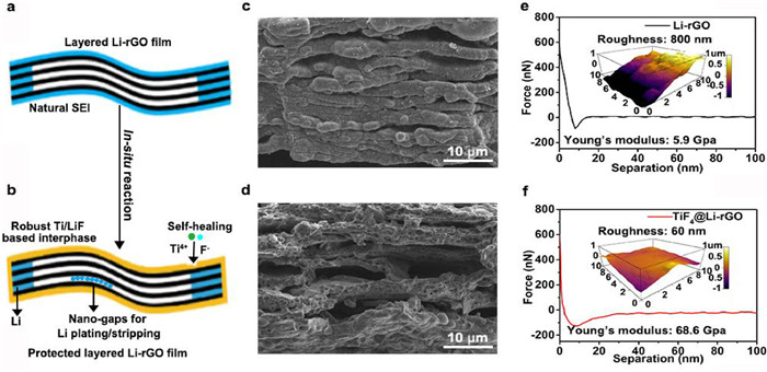
Schematic illustration of the in-situ process and physical characterization of the TiF4@Li-rGO electrode. Schematic illustration of the (a) Li-rGO and (b) TiF4@Li-rGO. Cross-sectional view of the (c) Li-rGO and (d) TiF4@Li-rGO electrode. The contrast stress force-distance curves of (e) Li-rGO and (f) TiF4@Li-rGO electrodes. The corresponding three-dimensional AFM scanning images of the surface for the different electrodes are shown as insets.
The synthesis process of the TiF4@Li-rGO electrode can be divided into three steps. Firstly, highly concentrated GO solution (5 mg/mL) was used to obtain freestanding GO films by vacuum filtration, zinc fluoride (ZnF2, anhydrous, 99%, Aladdin) was used as additive (1:1, w/w) in the GO solution to make the vacuum filtration more fluent. According to our previous work, the small addition of ZnF2 that aimed to make the filtration easier can be removed with filtrate and has little effect on the electrochemical performance [34]. After filtration, collected films were first dried in a vacuum oven at 60 ℃ overnight, tailored into small round pieces (~14 mm), then contacted with stainless steel at a high temperature of 350 ℃ to gain highly lithiophilic rGO film. After cooling down to room temperature, the Li-rGO was immersed into a supersaturated as-prepared solution using titanium tetrafluoride (TiF4, metal basis, 99.9%) as additive (10 wt% TiF4 in EC-EMC-DEC, 3:5:2, w/w) for 10 min, the color of the Li-rGO changes from khaki to black. The as-obtained TiF4@Li-rGO films were collected after washing with anhydrous DEC three times. All lithium metal and electrolyte contained experiment were carried out in an argon-filled glove box (Vigor, China, O2 and H2O content < 0.1 ppm). The as-prepared samples characterization and electrochemical measurements are attached in Supporting information.
The cross-sectional SEM images for Li-rGO and TiF4@Li-rGO electrode were shown in Figs. 1c and d. It is noted that large interspaces between these layered Li-rGO units are observed (Fig. 1c), which allows the electrolytes to access the units, thereby significantly increasing the surface area for electrochemical reactions. After immersing the Li-rGO film into the TiF4 contained electrolyte, the color of Li-rGO anode changes from khaki to black within minutes (Fig. S1 in Supporting information). The in-situ chemical reaction occurs between Li-rGO and TiF4, forming a Li2TiF6/LiF based SEI on Li-rGO (Fig. 1d and Fig. S2 in Supporting information). The hybrid SEI is expected to be an excellent lithium-ion conductor [35,36]. As verified by X-ray diffraction (XRD), the peaks at 2θ = 21.6°, 27.2° and 40.9° correspond to (101), (110) and (113) planes of Li2TiF6, respectively, and the peaks at 2θ = 38.7°, 44.9° and 65.4° correspond to (111), (200) and (220) planes of LiF, respectively (Fig. S3 in Supporting information) [37,38]. The SEI compositions were further investigated by in-depth X-ray photoelectron spectroscopy (XPS). As shown in Fig. S4 (Supporting information), in the case of the Ti 2p spectra, the peak of Ti 2p at 458.8 ev indicates the formation of Li2TiF6 associated with the peak of F 1s at 687.0 eV, whereas the peak at 464.5 eV shows the present of TiF3. The peaks of F 1s at 684.9 eV and Li 1s at 55.8 eV are assigned to LiF. Moreover, the peak of Li 1s at 54.6 eV corresponds to metallic Li. The energy dispersive spectroscopy (EDS) elemental mapping shows that F and Ti are homogeneously distributed on the SEI, and the chemical composition of the cross-sectional side and top surface of the electrode are similar (Figs. S5–S7 in Supporting information). Thus, the Li2TiF6 and LiF are chemically bounded into the artificial solid-state interphase on the exterior of layered Li-rGO units.
The retracted force-distance curve collected by atomic force microscope (AFM) shows a great leap that the Young's modulus value of hybrid solid-state interphase (68.6 GPa) is ten times stronger than the routine SEI on Li metal (5.9 GPa) (Figs. 1e and f), which transcends the threshold modulus value for suppressing Li-dendrite growth [39]. Such high-strength SEIs can suppress Li dendrites and conquer the huge volume fluctuation which further triggers repeated SEI collapse and reconstruction during cycling. Besides, the surface of the hybrid electrode is much smoother compared to the pristine Li-rGO. Therefore, the formed robust interphase not only can reduce the direct exposure of Li anode to electrolyte, but also can effectively prevent the short-circuit due to the damage of Li dendrites which triggers safety issues in a practical battery.
To account for the specific mechanism of the strategy we propose, galvanostatic charge/discharge test in symmetric cell was first compared between Li foil and TiF4@Li foil (Fig. S8 in Supporting information). The overpotentials of both Li foil and TiF4@Li foil steadily increase to 750 mV after 250 h, indicating that the planar SEI layer on Li foil still cannot bear the huge volume change due to the hostless nature (1 mAh corresponding to 5 µm volume change).
We further compare the voltage profiles of symmetric cells based on 3D layered TiF4@Li-rGO electrodes and Li-rGO electrodes. It should be noted that there are large voltage fluctuations in the initial several cycles for TiF4@Li-rGO based cells (Fig. S9a in Supporting information), which may be due to the hybrid SEI within the internal electrode is gradually forming and the initial ionic conductivity of the SEI is not good. As shown in Fig. S10 (Supporting information). The impedance of the cell significantly decreases through electro-chemical cycling activation for more than ten hours, which is likely due to the re-organization of the hybrid SEI layer (as will be explained below). After that, the symmetric cell shows long term cycling stability (Fig. S9b in Supporting information).
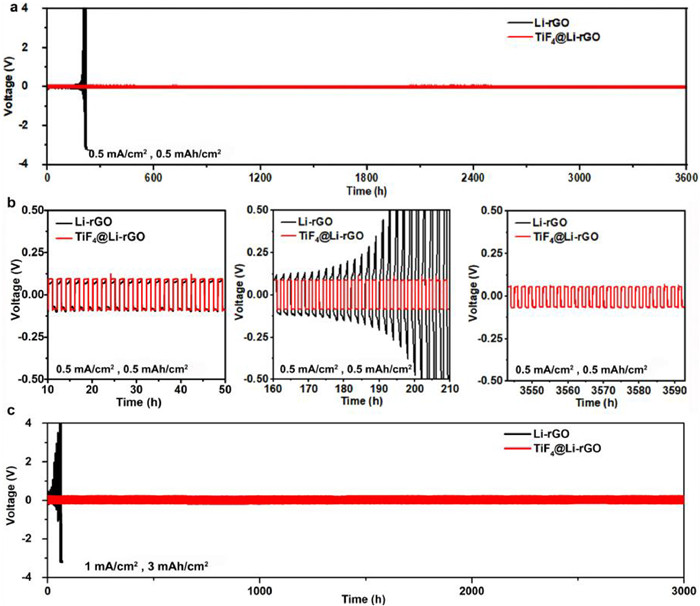
The symmetric cells also were investigated with current density fixed at 0.5 mA/cm2 and a capacity of 0.5 mAh/cm2 (Fig. 2a). As seen, it shows extraordinary long term cycling stability over 3600 h and maintains a relatively low overpotential of 90 mV (Fig. 2b). Furthermore, the cells with an increased areal density of 3 mAh/cm2 at 1 mA/cm2 were also employed to test the cycling stability. As seen in Fig. 2c, the cell undergoes a stable cycling over 3000 h with stable hysteresis. Remarkably, the cycling stability of TiF4@Li-rGO based cells under different testing conditions is much better than Li-rGO counterparts (only has stable cycling around 200 h). The magnified voltage profiles of the selected cycles (Figs. S11a–c in Supporting information) further indicate the stable cycling of TiF4@Li-rGO based cells with flat voltage plateau throughout the cycles. Additionally, the voltage profiles comparison between Li-rGO and TiF4@Li-rGO symmetric cell under various current densities and areal capacity are also shown in Figs. S12 and S13 (Supporting information), respectively. Continuous flat charging and discharging plateaus can be observed under all applied current densities and areal capacities for the TiF4@Li-rGO based cells, suggesting its capability of working under all applied current densities and areal capacities for varied purposes.
Figure 2
Figure 2.
Electrochemical characterizations of the symmetric cells for Li stripping/plating. Galvanostatic cycling of symmetric Li-rGO anode (black) and TiF4@Li-rGO anode (red) with current density fixed at (a) 0.5 mA/cm2 and stripping/plating capacity of 0.5 mAh/cm2, and (b) corresponding enlarged view of voltage profiles at different cycles. (c) Cycling stability test with current density fixed at 1 mA/cm2 and stripping/plating capacity of 3 mAh/cm2.
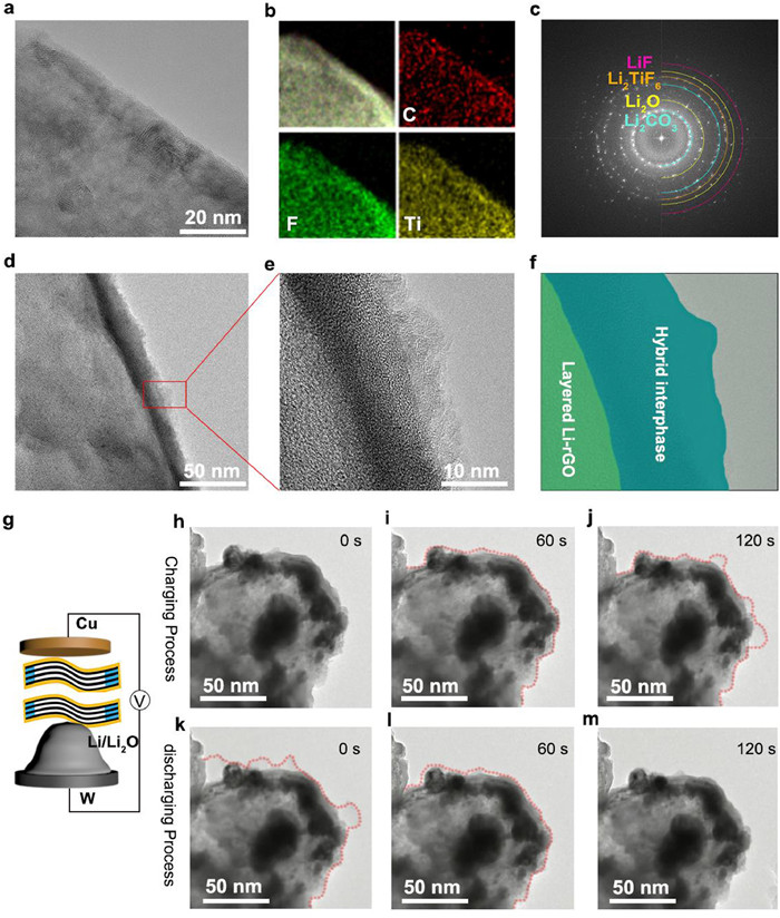
To gain further insight into the mechanism of how the TiF4@Li-rGO based cells achieve long-term cycling stability, high-resolution TEM was used to investigate the detailed structure of SEI before and after cyclic activation. We observe that the SEI structure is no longer an irregular distribution of organic and inorganic compound reported previously after reacting the layered Li-rGO unit with TiF4 contained electrolytes [40], the SEI possesses ultrafine crystals across the layered Li-rGO unit (Fig. 3a and Fig. S14 in Supporting information), the as-formed SEI layer mainly contains Li2TiF6, LiF, TiF3, Li2O and Li2CO3, as confirmed by EDS mapping and selected area electron diffraction (Figs. 3b and c). The Li2O and Li2CO3 mainly come from the decomposition of carbonate electrolyte, which can be assigned to the thermo-dynamic instability of Li anode against carbonate molecules [41]. After electrochemical activation, it is noted that the hybrid SEI is reorganized and a thin layer amorphous matrix forms on the hybrid interphase, which can be derived from the electrolyte decomposition (Figs. 3d–f). Despite a slightly decreased value (25.6 GPa) of Young's modulus (Fig. S15 in Supporting information), the reconstructed SEI greatly facilitates the Li-ion migration through the interphase, in agreement with the cycling performance and EIS tests (Figs. S9 and S10). Therefore, we believe that the preformed robust interphase and additional TiF4 additive play a crucial role in forming the final stable SEI, whose structure should be more ordered owing to the introduction of Li2TiF6. It has been reported that the ordered nature of a hybrid structure can provide enhanced mechanical durability, making it more robust upon cycling [42].
Figure 3
Figure 3.Ex-situ and in-situ TEM characterization of the hybrid interphase for 3D layered TiF4@Li-rGO electrode. (a) HRTEM image of the hybrid interphase for TiF4@Li-rGO electrode before activation. (b) Composition analysis of the hybrid interphase for TiF4@Li-rGO by energy-dispersive X-ray spectroscopy mapping. (c) SAED (selected area electron diffraction) of the hybrid interphase for TiF4@Li-rGO. (d) TEM image of the hybrid interphase for TiF4@Li-rGO electrode after activation at low magnifications. (e) HRTEM image of the hybrid interphase for TiF4@Li-rGO electrode after activation. (f) Schematics of the observed hybrid interphase structure on TiF4@Li-rGO. (g) Scheme of in-situ TEM cell configuration. in-situ TEM images of the Li (h-j) charging and (k-m) discharging process on Cu grid decorated with nano-level TiF4@Li-rGO taken at different times.
To understand the feature of nanogaps between TiF4@Li-rGO, we used in-situ TEM to observe the Li plating/stripping processes. Two electrodes (Li metal and TiF4@Li-rGO electrodes) are separated by natively formed Li oxide/nitride on Li metal as the electrolyte (Fig. 3g). When an appropriate bias was applied across the two electrodes, Li ions began to flow into the TiF4@Li-rGO electrode. Video S1 (Supporting information) presents such a plating process clearly and selected snapshots along the timeline are presented in Figs. 3h–j. At first, the lithium ions traversed the hybrid interphase and homogeneously deposited into the nanogaps. After the nanogaps were filled up with lithium, the lithium ions then deposited on the outside of the unit. Obviously, the robust hybrid interphase maintains its original appearance during the whole charging process. The lithium plating process is reversible, as presented in Video S2 (Supporting information). When the lithium was stripped out from the nanogaps, the outside lithium was first stripped and then the inner lithium was extracted (Figs. 3k–m). During the charging and discharging processes, the layered TiF4@Li-rGO unit was well protected without obvious volume change. Such unique structure can significantly improve the stability of Li metal anode as the direct exposure of Li metal to electrolyte is prevented.
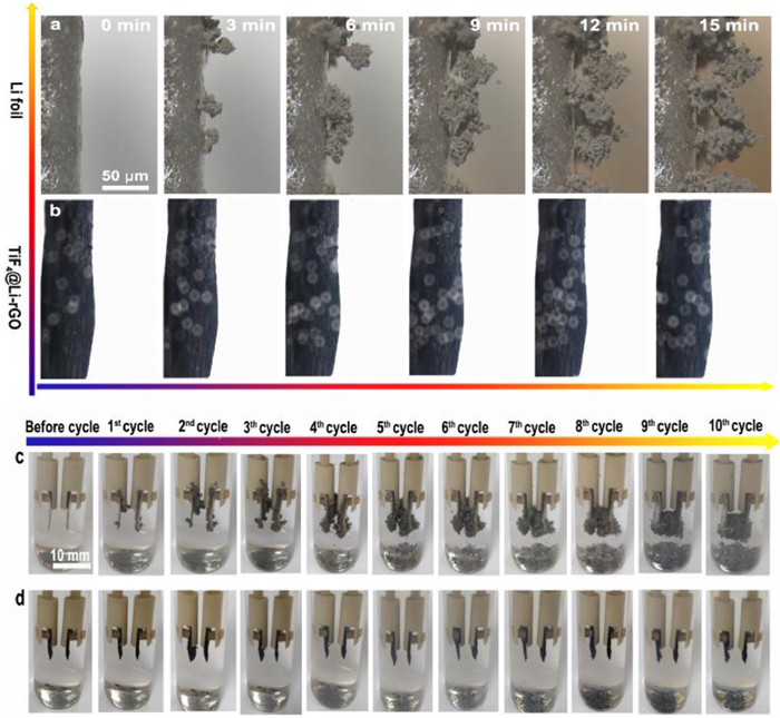
The liquid cell has been established for visualizing the evolution of lithium metal anodes during the charging and discharging process using operando optical microscopy. The proof-of-principle of the method directly characterizes electrochemical process under realistic conditions. Figs. 4a and b were taken at discrete time points separated by a fixed 3-min interval. It is observed that the Li foil electrode is prone to forming a moss-like dendritic structure. In comparison, the TiF4@Li-rGO electrode did not form the dendritic structure. Furthermore, it is seen that the overall volume maintained the same level. Optical observation of each electrode at different plating and stripping cycles was shown in Figs. 4c and d. As seen, once the process initiated, the surfaces of Li electrode became rough, and protrusions started to appear along the edge of the Li electrode. With the cycle proceeding, the protrusions gradually grew up and aggregated to form moss-like dendrites. After 10 cycles, the repeated process could produce a porous Li metal. In contrast, the surface of TiF4@Li-rGO electrode maintained smooth with no sign of protrusions upon cycling.
Figure 4
Figure 4.
Optical microscopy studies of lithium metal anodes during cycling at a current density of 2 mA/cm2. in-situ investigation of Li-ion plating behavior with (a) Li foil and (b) TiF4@Li-rGO during continuous plating on corresponding electrodes. Electrode surface morphology evolution images of the front surfaces of the (c) Li foil and (d) TiF4@Li-rGO electrode in the symmetric transparent cell.
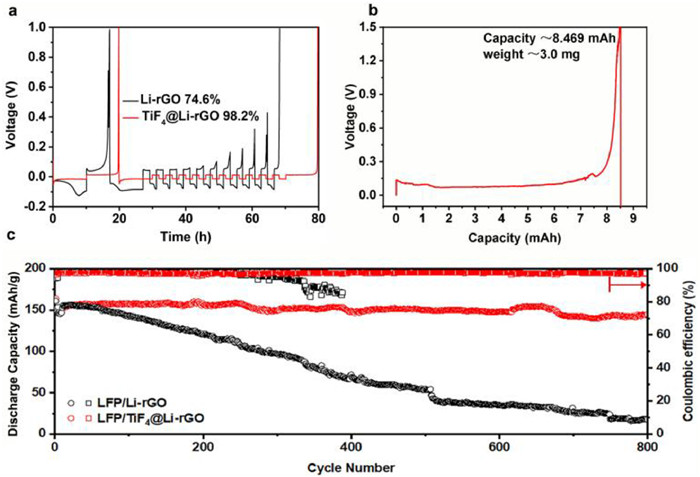
The demonstrated strategy significantly enhances the Coulombic efficiency (CE) of Li metal anodes and meets the demand of high-efficiency rechargeable batteries. Here, Aurbach CE test was used to obtain an accurate determination of CE between TiF4@Li-rGO and Li-rGO [43]. As shown in Fig. 5a, the cell with TiF4@Li-rGO achieves a high CE of 98.2%, while the CE for the cell with Li-rGO is just 74.6%. Additionally, after stripping Li metal from the TiF4@Li-rGO composite electrode to 1.5 V at a fixed current density of 0.5 mA/cm2, the voltage profile shows a total capacity of 8.469 mAh. Therefore, the total specific capacity can be calculated by dividing total capacity by the weight of proposed matrix and the result is 2823.0 mAh/g, which is very close to the theoretical capacity of pristine Li (Fig. 5b). High CE means the great potential for full batteries. When paired wth LiFePO4 (LFP) based full batteries, the LFP/TiF4@Li-rGO cell presented a stable cycling performance and delivered a specific capacity of 144.8 mAh/g (with capacity retention of 88.3%) after 800 cycles. On the contrary, the LFP/Li-rGO full cell can only deliver a low specific capacity of 17.7 mAh/g (with capacity retention of 11.0%) under the same condition (Fig. 5c). Notably, LFP/TiF4@Li-rGO cell with high mass loading shows poor cycling performance (with capacity retention of 79.3% after 200 cycles, as shown in Fig. S16 in Supporting information), which is due to that the voids between rGO layers are not large enough to deposit more Li, as verified by in situ TEM experiment above. The superior discharge capacity in long-term cycling demonstrates that con-structing a unique architecture is an effective way to enhance cycling stability. The relevant experimental results (Figs. S17 and S18 in Supporting information) further demonstrate the robust SEI on the 3D layered Li-rGO anode. The as-formed 3D hybrid interphase on Li-rGO has excellent passivation, homogeneity, and mechanical strength, which can inhibit the dendritic formation and tolerate the huge interface fluctuation, thus effectively preventing the continuous depletion of electrolyte and fresh Li.
Figure 5
Figure 5.
Electrochemical performance of TiF4@Li-rGO electrodes. (a) Aurbach measurement of the coulombic efficiency for the TiF4@Li-rGO and Li-rGO electrodes (b) Full Li stripping curve of the TiF4@Li-rGO electrode to 1.5 V versus Li+/Li, which shows a specific capacity of ~2823.0 mAh/g. (c) Performance of full cell comparison between LFP/Li-rGO and LFP/TiF4@Li-rGO cells.
To further investigate the influence of TiF4 on the LFP based full cells, an extra experiment was carried out by using different amount of TiF4 as an additive in the electrolyte. We firstly measured the cycling stability for each cell. As shown in Fig. S19 (Supporting information), the cell with 1 wt% TiF4 additive can deliver a specific capacity of 161 mAh/g at 200th cycle (with CE of 97.9%), but the specific capacity for cells with 3 wt% TiF4 additive and 5 wt% TiF4 additive decreases to 147 mAh/g (with CE of 95.8%) and 130 mAh/g (with CE of 87.7%) at 200th cycle, respectively. The cycling profile displays a fast capacity declining rate with the increasing content of TiF4 additive and a sharp drop of CE is observed when the concentration is increased to 5 wt% TiF4, indicating that excessive amount of TiF4 is harmful for the LFP cathode. SEM and TEM EDS mapping of the LFP cathode after cycling were performed to explain the circumstance (Figs. S20 and S21 in Supporting information). As seen, the surface of LFP covers Ti and F, which can be contributed to LixTiF4+x deposition. The deposition would become thicker and thicker upon cycling, resulting in the impediment of Li+ transport and the consumption of Li ions.
In conclusion, we report a new architecture of in-situ preformed artificial robust hybrid interphase associated with 3D layered Li-rGO framework, which exhibits high-efficiency Li deposition and long-term cycling performance after activation. The as-obtained SEI has outstanding mechanical strength, homogeneity, and passivation properties which outperforms the conventional electrolyte-derived SEI. The resulting anode enables stable cycling of Li symmetric cells over 3600 h. The modified anode based full cells exhibit outstanding cycling performance and high Coulombic efficiency as well. The proposed strategy opens up a promising avenue for promoting the practical applications of lithium metal batteries.
Declaration of competing interest
The authors declare that they have no known competing financial interests or personal relationships that could have appeared to influence the work reported in this paper.
Acknowledgments
This work is supported by the National Key Research and Development Program of China (No. 2018YFA0209600); Science and Technology Key Project of Guangdong Province, China (No. 2020B010188002); Guangdong Innovative and Entrepreneurial Research Team Program (No. 2019ZT08L075); Foshan Innovative and Entrepreneurial Research Team Program (No. 2018IT100031); Guangdong Pearl River Talent Program (No. 2019QN01L054); National Natural Science Foundation of China (No. 22176063) and the Fundamental Research Funds for the Central Universities (No. 2020ZYGXZR061).
Supplementary materials
Supplementary material associated with this article can be found, in the online version, at doi:10.1016/j.cclet.2022.06.025.
X. B. Cheng, R. Zhang, C. Z. Zhao, Q. Zhang, Chem. Rev. 117 (2017) 10403-10473. doi: 10.1021/acs.chemrev.7b00115
[42]
S. H. Choi, S. K. Park, J. K. Lee, Y. C. Kang, J. Power Sources. 284 (2015) 481-488. doi: 10.1016/j.jpowsour.2015.03.026
[43]
B. D. Adams, J. Zheng, X. Ren, W. Xu, J. G. Zhang, Adv. Energy Mater. 8 (2018) 1702097. doi: 10.1002/aenm.201702097
Figure 1
Schematic illustration of the in-situ process and physical characterization of the TiF4@Li-rGO electrode. Schematic illustration of the (a) Li-rGO and (b) TiF4@Li-rGO. Cross-sectional view of the (c) Li-rGO and (d) TiF4@Li-rGO electrode. The contrast stress force-distance curves of (e) Li-rGO and (f) TiF4@Li-rGO electrodes. The corresponding three-dimensional AFM scanning images of the surface for the different electrodes are shown as insets.
Figure 2
Electrochemical characterizations of the symmetric cells for Li stripping/plating. Galvanostatic cycling of symmetric Li-rGO anode (black) and TiF4@Li-rGO anode (red) with current density fixed at (a) 0.5 mA/cm2 and stripping/plating capacity of 0.5 mAh/cm2, and (b) corresponding enlarged view of voltage profiles at different cycles. (c) Cycling stability test with current density fixed at 1 mA/cm2 and stripping/plating capacity of 3 mAh/cm2.
Figure 3Ex-situ and in-situ TEM characterization of the hybrid interphase for 3D layered TiF4@Li-rGO electrode. (a) HRTEM image of the hybrid interphase for TiF4@Li-rGO electrode before activation. (b) Composition analysis of the hybrid interphase for TiF4@Li-rGO by energy-dispersive X-ray spectroscopy mapping. (c) SAED (selected area electron diffraction) of the hybrid interphase for TiF4@Li-rGO. (d) TEM image of the hybrid interphase for TiF4@Li-rGO electrode after activation at low magnifications. (e) HRTEM image of the hybrid interphase for TiF4@Li-rGO electrode after activation. (f) Schematics of the observed hybrid interphase structure on TiF4@Li-rGO. (g) Scheme of in-situ TEM cell configuration. in-situ TEM images of the Li (h-j) charging and (k-m) discharging process on Cu grid decorated with nano-level TiF4@Li-rGO taken at different times.
Figure 4
Optical microscopy studies of lithium metal anodes during cycling at a current density of 2 mA/cm2. in-situ investigation of Li-ion plating behavior with (a) Li foil and (b) TiF4@Li-rGO during continuous plating on corresponding electrodes. Electrode surface morphology evolution images of the front surfaces of the (c) Li foil and (d) TiF4@Li-rGO electrode in the symmetric transparent cell.
Figure 5
Electrochemical performance of TiF4@Li-rGO electrodes. (a) Aurbach measurement of the coulombic efficiency for the TiF4@Li-rGO and Li-rGO electrodes (b) Full Li stripping curve of the TiF4@Li-rGO electrode to 1.5 V versus Li+/Li, which shows a specific capacity of ~2823.0 mAh/g. (c) Performance of full cell comparison between LFP/Li-rGO and LFP/TiF4@Li-rGO cells.

 DownLoad:

 下载:
下载:


