The Collaborative Innovation Center for Eco-Friendly and Fire-Safety Polymeric Materials (MoE), National Engineering Laboratory of Eco-Friendly Polymeric Materials (Sichuan), State Key Laboratory of Polymer Materials Engineering, College of Chemistry, Sichuan University, Chengdu 610064, China
Received Date:
16 April 2022 Accepted Date:
18 May 2022 Revised Date:
12 May 2022 Available Online:
15 May 2023
Abstract:
Separators is indispensable for the normal operation of lithium-ion batteries (LIBs). However, the widely used commercial polyolefin separators have some inherent deficiencies such as poor thermotolerance, high inflammability and inferior electrolyte wettability, which restrict their further applications of the advanced and safe batteries. Herein, we design a novel thermotolerant (a shrinkage percentage of 0% at 300 ℃) and flame retarded aerogel separator consisting of aramid nanofibers (ANFs). Because of its high porosity (86.5% ± 6.1%) and excellent electrolyte uptake (695%), the ANFs aerogel separator has an ionic conductivity of 1.04 mS/cm and a high lithium-ion transference number (0.67), which can endow LIBs with outstanding rate performance and superior cycling performance. Specifically, the ANFs aerogel separator-based batteries possess a discharge specific capacity of 102 mAh/g with a capacity retention of 90.7% and a Coulombic efficiency of 99.3% after 600 cycles at 5 C. In addition, under an operated temperature of 90 ℃, the battery with ANFs aerogel separator can still conduct the very steady charge-discharge, presenting a capacity retention of 90.1% and a Coulombic efficiency of 99.6% after 200 cycles at 3 C. Accordingly, the separator can probably serve as a potential candidate for application to advanced and safe LIBs.
Lithium-ion batteries (LIBs) have become widely applied in our daily lives due to their low self-discharge, high power density, lightweight design, and long life [1-3]. However, with the increasing demand of LIBs in advanced fields like energy storage systems and electric vehicles, the potential safety problems of LIBs caused by misusage, short circuits, local overheating, etc. have attracted more concerns [4]. Separators are essential for ensuring the normal operation of LIBs, as they permit the migration of ions and prevent internal short circuits during the charge and discharge process [5,6]. Microporous polyolefin separators are widely used in LIBs, such as polyethylene (PE) and polypropylene (PP). They have several merits like excellent electrochemical stability and good mechanical strength, but poor thermal stability, high inflammability, and low electrolyte wettability limit their further application in burgeoning energy fields [7,8]. For PP (160 ℃) and PE (136 ℃) separators, their low melting points make them suffer serve shrinkages and then lead to internal short circuits with elevated temperature, which further generates a lot of heat and finally gives rise to catching fire and even explosion [9,10]. The poor wettability of the electrolyte of polyolefin separators also increases the probability of a partial filling of the separators with electrolyte, resulting in sluggish and irreversible Li+ transport, and further causes inferior rate performance [11,12].
To overcome the above problems, plenty of efforts have been performed. One of the most widely adopted strategies is to physically modify the polyolefin separator with functional coatings consisting of polymer binder and ceramic nanoparticles (e.g., Al2O3 and SiO2) [13,14]. However, the coatings not only would decrease the porosity of the separator, thus hindering the migration of Li ions, but also may peel off from the separator during long cycling due to their physical adhesion [15]. In order to improve adhesive strength between modified coatings and separators, a covalent grafting method is employed [16,17]. Nevertheless, the chemical modification process inevitably affects the structure stability of the separator and often involves expensive, harsh, and complex procedures [18]. Alternatively, it is highly popular to replace polyolefin separators by developing advanced candidates based on more thermotolerant or even fire-resistant polymers like cellulose [19], poly(vinylidene difluoride) (PVDF) [20,21], polyacrylonitrile (PAN) [22,23], polyimide (PI) [18,24], aramid nanofibers (ANFs) [25-30], etc.
Derived from the poly(p-phenylene terephthalamide) (PPTA) products [31], ANFs-based separators have gained much attention recently considering their excellent thermal stability and outstanding mechanical performance. Different from some ANFs composite separators [32-34], Patel et al. [26] reported a pure ANFs separator by vacuum-assisted self-assembly. Although the obtained separator possessed high modulus, good thermal stability, and self-extinguishing characteristics, the cycling performance of LIBs using the pure ANFs separator was far from the commercial separators-based LIBs due to its lower porosity. Li et al. [27] prepared a ANFs separator by a paper-making method with an addition of methoxy polyethylene glycol (mPEG) to prevent aggregation of the chains when polymerizing PPTA. However, the porosity and ionic conductivity of this modified ANFs separator were lower than those of the PP separator, resulting in a lower discharging capacity at high rates. It therefore remains a great challenge to attain the pure ANFs separator-based LIBs with excellent electrochemical performance, such as high rate and long life.
In this work, a novel aerogel separator with good flame retardance and high thermal stability (a shrinkage percentage of 0% at 300 ℃) is designed rationally. The aerogel separator consisting of interconnected aramid nanofibers (ANFs) derived from Kevlar fibers, i.e., ANFs aerogel separator, possesses a three-dimensional network framework and abundant micro/mesopores, which contribute to a high porosity of 86.5% ± 6.1% and a superior electrolyte uptake of 695%, so as to enable a good ionic conductivity of 1.04 mS/cm and a large lithium-ion transference number of 0.67. As a result, the LIBs with ANFs aerogel separators show outstanding rate capability and superior cycling performance, namely, a capacity retention of 90.7% and a Coulombic efficiency of 99.3% can be attained after 600 cycles at 5 C. Significantly, after 200 cycles at 3 C under 90 ℃, the ANFs aerogel separator battery retains 90.1% of its capacity and has a Coulombic efficiency of 99.6%. Therefore, it can be estimated that the ANFs aerogel separator is potentially promising to develop the safe and high-performance LIBs.
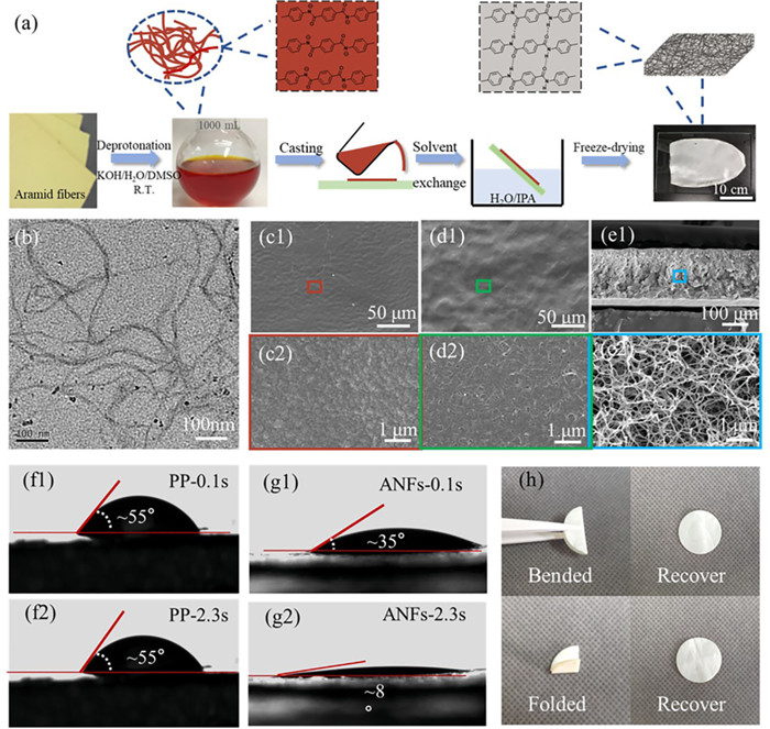
As shown in Fig. 1a, the preparation procedure of ANFs aerogel separator mainly involves facile and mild four steps, i.e., deprotonation to form the ANFs with negatively charged amide bonds, casting film, solvent exchange for gelation by restoring the neutral structure of PPTA, and freeze-drying to fix the three-dimensional ANFs network structure. According to our previous work [35], about 500 mL DMSO dispersion (1.5 wt%) of the ANFs with a diameter of 9.9 ± 1.9 nm was successfully obtained after the deprotonation of the aramid fibers, which is demonstrated by the TEM observation (Fig. 1b). Then, a large area of ANFs aerogel separator (about 180 cm2) with a neutral structure of PPTA was prepared after casting, solvents exchange, and freeze-drying in sequence. In comparison, the ANFs aerogel separator with a very low density of 0.04 g/cm3 is much lighter than commercial PP separator (0.43 g/cm3).
Figure 1
Figure 1.
(a) Preparation process of the ANFs aerogel separator. (b) TEM image of the ANFs dispersion. SEM images of (c1, c2) upper surface, (d1, d2) lower surface, and (e1, e2) cross section of the ANFs aerogel separator. Digital pictures of contact angles of (f1, f2) the PP separator and (g1, g2) the ANFs aerogel separator after the electrolyte dripping for different time. (h) Photographs of the ANFs aerogel separator after bending and folding.
The chemical structures of ANFs aerogel separator were characterized by FT-IR and Raman, respectively. For the FT-IR spectra (Fig. S1 in Supporting information), it can be found that the characteristic peaks of the ANFs aerogel separator at 3325, 1646 and 1543 cm−1 assigned to N-H stretching vibration, amide I band and amide II band, respectively, are completely consistent with those of the aramid fibers, indicating that the neutral structure of PPTA in the ANFs has been successfully restored after the solvents exchange. It should be noted that for the ANFs aerogel separator both peak intensity and peak width of the N-H stretching vibration at 3325 cm−1 are slightly smaller than the aramid fibers, which could be attributed to the weakened internal hydrogen bond after deprotonated and restructured. In Raman spectra (Fig. S2 in Supporting information), the characteristic peaks of the ANFs separator also are identical to those of the aramid fibers, further supporting the above results. The SEM observation indicates that both the upper surface (Figs. 1c1 and c2) and the lower surface (Figs. 1d1 and d2) of the ANFs aerogel separator possess a dense structure. However, the cross-sectional SEM images (Figs. 1e1 and e2) show that the interior of the ANFs aerogel separator is a 3D network composed of entangled nanofibers, which reflects its high specific surface area and hierarchical pore structure, being far richer than PP separator (Figs. S3a and b in Supporting information). The structural difference between surface and interior of the ANFs aerogel separator may ascribe to a faster phase separation corresponding to more drastic solvent exchange at the liquid-solid interface.
In order to determine the size of the pores and specific surface area of the ANFs aerogel separator, the nitrogen adsorption-desorption testing was conducted. According to the IUPAC classification [36], Fig. S4 (Supporting information) shows that the adsorption-desorption curve with a hysteresis loop at higher relative pressures is categorized as type-IV isotherms, indicating abundant porous structures including micropores and mesopores. Moreover, the BET specific area is 151.62 m2/g, and the corresponding average pore diameter is 14.76 nm. As listed in Table S1 (Supporting information), the ANFs aerogel separator has a porosity up to 86.5% ± 6.1%, while the porosity of the PP separator is only 39.8% ± 5.3%. Plenty of porous structures are not only beneficial to the absorption of electrolytes, but also provide a lot of paths for Li+ migration to enhance the ion conductivity [37,38].
It can be supposed that the diverse polar groups on the PPTA molecular chain will be very conducive to the absorption of polar organic electrolytes. As illustrated in Figs. 1f and g, the contact angle of the PP separator is significantly larger than that of the ANFs aerogel separator. Furthermore, after the electrolyte droplet dripped for 2.3 s, the contact angle of the PP separator still maintained at 55°, while that of the ANFs aerogel separator reduced from 35° to 8°. These results demonstrate that the ANFs aerogel separator possesses better electrolyte wettability and quicker electrolyte absorption than those of the PP separator. Furthermore, the ANFs aerogel separator has a high electrolyte uptake of 695%, which is twice as high as that of the PP separator (169%). Additionally, it is seen from Fig. 1h that the ANFs aerogel separator shows a good flexibility and can still maintain its original shape after bending and folding. As illustrated in Fig. S5 (Supporting information), the tensile strength of the ANFs separator was 0.75 ± 0.02 MPa and the elongation at break was 6.5% ± 0.2%. The moderate mechanical properties of the ANFs separator are probably due to its increasing porosity. Overall, the ANFs aerogel separator is able to meet the requirements for assembling batteries.
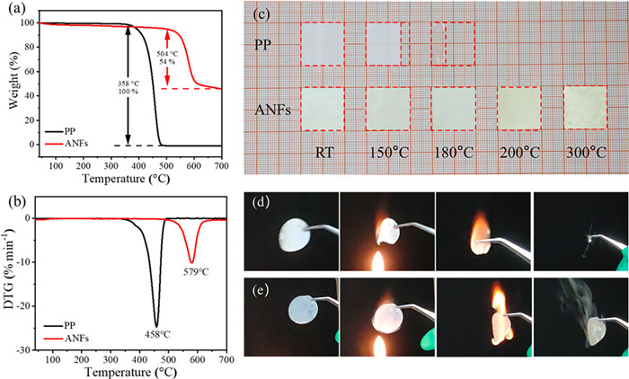
It is essential that separators maintain a high thermal stability for the safety of LIBs [39]. The thermogravimetric analysis shows no obvious weight loss for the ANFs aerogel separator up to 504 ℃ (Figs. 2a and b), which is the temperature at a weight loss of 5% (T5%), indicating its excellent thermotolerance. By contrast, the PP separator with a T5% of 358 ℃ has been completely decomposed at 500 ℃. Temperature-related changes in the size and shape of the separator are more intuitively related to its thermal stability [40]. As shown in Fig. 2c, the PP separator exhibits severely dimensional shrinkage at 150 ℃ for 1 h, and further the percentage of shrinkage increases rapidly to 100% (Table S2 in Supporting information) with elevating the temperature to 200 ℃. In comparison, no thermal shrinkage occurs even at temperature up to 300 ℃ in ANFs aerogel separator. As illustrated in Fig. S6 (Supporting information), after heat treatment at 300 ℃, the SEM images of the ANFs aerogel separator show no obvious change comparing with itself before heat treatment and there is still a nanofibers-interconnected 3D network. Furthermore, before and after heat treatment, there is almost no significant difference in the FTIR spectra of the ANFs aerogel separator (Fig. S7 in Supporting information). The excellent thermal stability of ANFs aerogel separator will not only contribute to the improving safety of batteries, but also provide a probably alternative for the application of separators in high-temperature batteries, which will be further discussed below.
Figure 2
Figure 2.
(a) TGA and (b) DTG curves of the PP separator and the ANFs aerogel separator. (c) Digital photos of the PP separator and the ANFs aerogel separator after heat treatment for 1 h under different temperature. Burning test of (d) PP separator and (e) ANFs aerogel separator wetted by the electrolyte.
The burning tests were conducted to study the tolerance of different separators when exposed to flame. The separators were wetted by the electrolyte before ignition. As illustrated in Figs. 2d and e, the ANFs aerogel separator is more fireproof than the PP separator. In detail, it can be found from Video S1 (Supporting information) that the PP separator shrank seriously when it was close to the flame, and there was only a little residue after burning. On the contrary, the ANFs aerogel separator (Video S2 in Supporting information) self-extinguished rapidly, and there was no obviously dimensional shrinkage. Moreover, when the ANFs separator was ignited again (Video S3 in Supporting information), the flame can still be extinguished quickly, indicating a good flame retardancy. The flame retardant ANFs aerogel separator could be effective in improving the fire safety of batteries.
The ionic conductivity has a great impact on achieving high-rate capacity and battery reversibility [41]. The lithium ion (Li+) conductivities of different separators were characterized by EIS. Fig. S8a (Supporting information) gave the Nyquist plots of different separators at ambient temperature, and their ionic conductivities calculated by Eq. S5 (Supporting information) were listed in Table S1. The ionic conductivity of the PP separator is 0.99 mS/cm, and the ANFs aerogel separator possesses an improved value of 1.04 mS/cm. This result could be owing to the higher porosity and the stronger electrolyte uptake capability of the ANFs aerogel separator, which are beneficial to the Li+ transport.
Moreover, the Li+ transference number (tLi) is considered as a fundamental parameter for evaluating the performance of LIBs [11]. The anions dissociated from the lithium salts may accumulate to cause a serious polarization because of some side reactions. Therefore, it is beneficial to the cycling performance of LIBs to acquire high tLi [42]. According to Figs. S8b and c (Supporting information), the calculated tLi values are given in Table S1. The ANFs aerogel separator has a higher tLi of 0.67, compared with the PP separator (0.37). The high tLi of the ANFs aerogel separator indicates that the batteries based on the ANFs aerogel separators will exhibit an excellent rate performance. The reasons of the high tLi could be as follows: The nanofibers-interconnected three-dimensional network and the abundant porous structures inside the ANFs aerogel separator supply a plenty of paths for the movement of Li+. And many polar groups of the ANFs aerogel separator are conducive to electrolyte absorption, reducing the impedance of Li+ transport [43,44]. Moreover, as the donors, the nitrogen atoms contribute to the desolvation of Li+ thus accelerating the migration of Li+ [45].
The electrochemical stability of the separator is one key factor that determines the work voltage range of LIBs. Herein, the electrochemical windows of the PP separator and the ANFs aerogel separator were investigated by linear voltammetry. As illustrated in Fig. S8d (Supporting information), the cell based on the PP separator exhibits steady currents at voltages below 4.8 V versus Li+/Li, but the voltage corresponding to the stable currents for the ANFs aerogel separator-based cell slightly reduces to 4.5 V. Nevertheless, as the practical work voltage range of LIBs is from 3.0 V to 4.2 V, the ANFs aerogel separator can still meet the requirements.
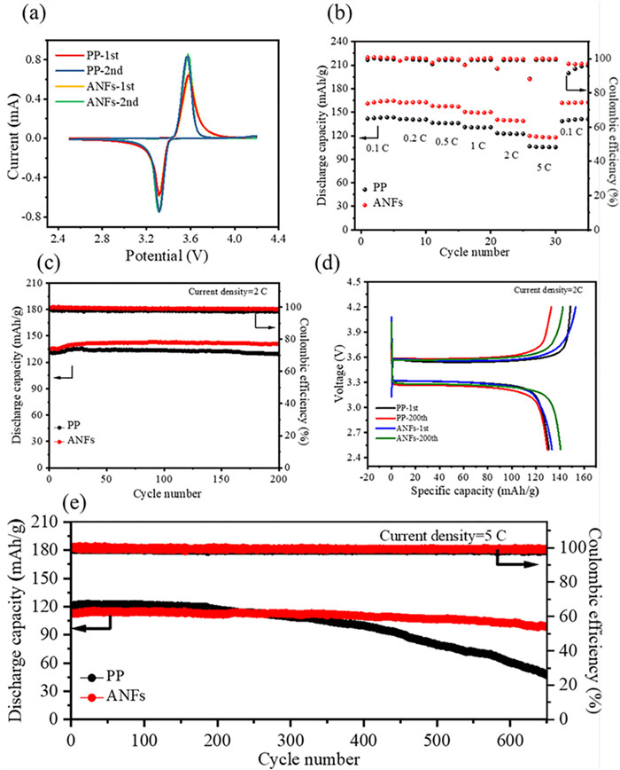
Moreover, the stability of the different separators in reductive and oxidative environment was investigated by CV, as shown in Fig. 3a. When charging and discharging a half cell with LiFePO4(LFP) as the cathode, the oxidation plateau and reduction plateau potentials are usually 3.6–3.7 V and 3.2–3.3 V, respectively [46]. The CV curves of the PP separator and the ANFs aerogel separator are similar, and the redox peak potentials are close to the typical plateau potentials of charge and discharge. Moreover, the redox peaks of the ANFs aerogel separator did not change significantly after 2 cycles, indicating its excellent electrochemical stability.
Figure 3
Figure 3.
(a) Cyclic voltammetry curves and (b) rate performance of LFP/Li half cells with different separators. (c) Cycling performance and (d) charge/discharge profiles of LFP/Li half cells with different separators at 2 C. (e) Long cycling performance of LFP/Li half cells with different separators at 5 C.
Fig. 3b exhibits the discharge specific capacities of cells using different separators at current densities ranging from 0.1 C to 5 C. With the increase of current density, the discharge specific capacities of both the PP separator and the ANFs aerogel separator decrease gradually, but the ANFs aerogel separator shows the higher discharge specific capacities at all C-rates comparing with the PP separator. It is worthy to note that when returned to 0.1 C, the Coulombic efficiency of the ANFs aerogel separator was obviously higher than that of the PP separator, and the discharge specific capacity of up to 162.6 mAh/g for the ANFs aerogel separator can be obtained at 0.1 C, being close to that of the initial cycles. The above results indicate that the ANFs aerogel separator possesses better rate performance than the PP separator no matter high or low C-rate, in accord with the high ionic conductivity and large tLi of the ANFs aerogel separator.
Besides the rate performance, the long-cycle test of the battery is also indispensable for studying the battery performance. As illustrated in Fig. S9 (Supporting information), the ANFs aerogel separator exhibits slightly higher discharge specific capacity and Coulombic efficiency than those of the PP separator at 1 C. After 200 cycles at 2 C (Fig. 3c), the discharge specific capacity and the Coulombic efficiency of the battery using the ANFs aerogel separator are 140 mAh/g and 98.6%, respectively, while those of the PP separator are only 129 mAh/g and 97.3%. The charge/discharge profiles in Fig. 3d demonstrate that the ANFs aerogel separator-based battery has a lower polarization voltage of 244 mV at 2 C after 200 cycles than that of the PP separator (332 mV). Significantly, at 5 C (Fig. 3e), the discharge specific capacity based on the ANFs aerogel separator can be maintained at 102 mAh/g after 600 cycles, with 90.7% of capacity retention and 99.3% of Coulombic efficiency. In contrast, the discharge specific capacity of the PP separator battery reduces observably to 61 mAh/g accompanying with a capacity retention of only 50.3% and a Coulombic efficiency of 98.3% at 5 C after 600 cycles. From the above results, thanks to the high tLi and ionic conductivity, the ANFs aerogel separator endows the battery with outstanding long-cycle stability at high rates.
The interfacial compatibility between electrodes and separators also plays a key role in the cycling performance of batteries. In fact, lower interfacial resistance means better electron transfer efficiency of lithium ions [47]. As illustrated in Fig. S10 (Supporting information), the interfacial resistance of batteries using different separators after 0, 50 and 100 cycles at 1 C were investigated by the AC impedance spectra, and the inset is the equivalent circuit for the fitting to calculate the data. As displayed in Table S3 (Supporting information), with the increase of cycle numbers, the bulk impedance (Rb) value of the ANFs aerogel separator increases slightly, which is similar to the PP separator. However, the ANFs aerogel separator has a lower interfacial charge transfer resistance (Rct) than that of the PP separator. And the Rct value of the PP separator increases to 178.8 Ω, while the Rct value of the ANFs aerogel separator is only 136.8 Ω after 100 cycles, indicating the better interfacial compatibility. The lower Rct can accelerate the transport of lithium ion, thus revealing the reason why both Coulombic efficiency and specific capacity of the ANFs aerogel separator are well maintained.
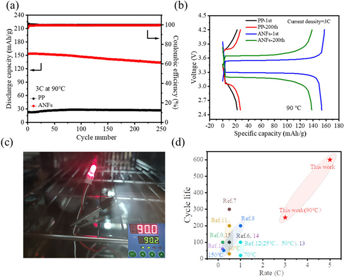
To assess the potential application of the ANFs aerogel separators in the safer LIBs, the LFP/Li half cells with 1 mol/L LiBOB in PC as the electrolyte were assembled to study the cycling performance at a high temperature of 90 ℃. As shown in Fig. 4a, the ANFs aerogel separator cell possesses superior cycling stability, and a discharge specific capacity of 138 mAh/g with a capacity retention of 90.1% is observed after 200 cycles at 3 C. Moreover, due to low thermal stability and poor electrolyte wettability, the PP separator cell at 90 ℃ and 3 C presents a high polarization voltage of 700 mV and an initial discharge specific capacity of only 20 mAh/g (Fig. 4b). By contrast, the ANFs aerogel separator cell exhibits a stable first charge-discharge curve, delivering a lower polarization voltage of 236 mV and a higher discharge specific capacity of 153 mAh/g. As a proof of concept, the ANFs aerogel separator-based cell under 90 ℃ steadily lights up a bulb for a long time (Fig. 4c). These results demonstrate that the thermotolerant ANFs aerogel separator can also endow LIBs with good performance at a high temperature.
Figure 4
Figure 4.
(a) Cycling performance and (b) charge/discharge profiles of cells with different separators at 90 ℃ at 3 C. (c) Digital picture of the cell with the ANFs aerogel separator lighting a bulb at 90 ℃. (d) Cycling performance comparison of the ANFs aerogel separator and other separators (The operating temperature of other examples was 25 ℃ except the marked examples, the corresponding references were listed in References of Supporting information).
Overall, by comparing with previously reported state-of-the-art ANFs separators, aerogel separators, and modified-PP separators (Fig. 4d and Table S4 in Supporting information), the ANFs aerogel separator-based LIBs not only show the ultra-long and highly stable cycle at a high rate of 5 C under ambient temperature, but also can deliver superior long-term cycling performance with superior capacity retention and Coulombic efficiency at 3 C under 90 ℃.
In this work, by a facile and mild strategy, we have successfully prepared the flexible ANFs aerogel separator from the aramid fibers. The ANFs aerogel separator possesses high porosity of 86.5% ± 6.1% and electrolyte uptake of 695%, which are significantly higher than those of the PP separator. And the ANFs aerogel separator has good flame retardancy and excellent thermal stability with a T5% of 504 ℃. Thanks to the nanofibers-interconnected 3D network and abundant porous structures, the batteries with the ANFs aerogel separators exhibit superior rate performance and ultra-long cycle performance at 5 C under room temperature. Significantly, when exposed to 90 ℃, the ANFs aerogel separator battery also possesses outstanding long-term cycling stability with the capacity retention of 90.1% after 200 cycles at 3 C. Overall, our work not only can facilitate the application of ANFs to advanced LIBs, but also provides one of potentially promising solutions to the safety of LIBs.
Declaration of competing interest
The authors declare that they have no known competing financial interests or personal relationships that could have appeared to influence the work reported in this paper.
Acknowledgmentss
This work was supported by National Natural Science Foundation of China (Nos. U19A2095, 51773134), the Sichuan Province Science and Technology Project (No. 2019YFH0112), the Fundamental Research Funds for the Central Universities, Institutional Research Fund from Sichuan University (No. 2021SCUNL201), and the 111 Project (No. B20001).
Supplementary materials
Supplementary material associated with this article can be found, in the online version, at doi:10.1016/j.cclet.2022.05.060.
[1]
H. Li, Z. Wang, L. Chen, X. Huang, Adv. Mater. 21 (2009) 4593–4607. doi: 10.1002/adma.200901710
Figure 1
(a) Preparation process of the ANFs aerogel separator. (b) TEM image of the ANFs dispersion. SEM images of (c1, c2) upper surface, (d1, d2) lower surface, and (e1, e2) cross section of the ANFs aerogel separator. Digital pictures of contact angles of (f1, f2) the PP separator and (g1, g2) the ANFs aerogel separator after the electrolyte dripping for different time. (h) Photographs of the ANFs aerogel separator after bending and folding.
Figure 2
(a) TGA and (b) DTG curves of the PP separator and the ANFs aerogel separator. (c) Digital photos of the PP separator and the ANFs aerogel separator after heat treatment for 1 h under different temperature. Burning test of (d) PP separator and (e) ANFs aerogel separator wetted by the electrolyte.
Figure 3
(a) Cyclic voltammetry curves and (b) rate performance of LFP/Li half cells with different separators. (c) Cycling performance and (d) charge/discharge profiles of LFP/Li half cells with different separators at 2 C. (e) Long cycling performance of LFP/Li half cells with different separators at 5 C.
Figure 4
(a) Cycling performance and (b) charge/discharge profiles of cells with different separators at 90 ℃ at 3 C. (c) Digital picture of the cell with the ANFs aerogel separator lighting a bulb at 90 ℃. (d) Cycling performance comparison of the ANFs aerogel separator and other separators (The operating temperature of other examples was 25 ℃ except the marked examples, the corresponding references were listed in References of Supporting information).

 DownLoad:

 下载:
下载:


