School of Materials Science and Engineering Key Laboratory of Advanced Technology for Materials Synthesis and Processing, Wuhan University of Technology, Wuhan 430070, China
b.
School of Materials, Shenzhen Campus of Sun Yat-sen University, Shenzhen 518107, China
l.gu@iphy.ac.cn (L. Gu). 1 These authors contributed equally to this work.
Received Date:
07 February 2022 Accepted Date:
07 May 2022 Revised Date:
10 March 2022 Available Online:
15 April 2023
Abstract:
Lithium rich layered oxide (LRLO) has been considered as one of the promising cathodes for lithium-ion batteries (LIBs). The high voltage and large capacity of LRLO depend on Li2MnO3 phase. To ameliorate the electrochemical performance of Li2MnO3, also written as Li(Li1/3Mn2/3)O2, we propose a strategy to substitute Mn4+ and Li+ in Mn/Li transition metal layer with Ti4+, which can stabilize the structure of Li2MnO3 by inhibiting the excessive oxidation of O2− above 4.5 V. More significantly, the unequal-valent substitution brings about the emergence of interlayer Li vacancies, which can promote the Li-ion diffusion based on the enlarged interlayer and increase the capacity by activating the Mn3+/4+ redox. We designed Li0.7[Li1/3Mn2/3]0.7Ti0.3O2 with high interlayer Li vacancies, which presents a high capacity (290 mAh/g at 10 mA/g) and stable cycling performance (84% over 60 cycles at 50 mA/g). We predict that this strategy will be helpful to further improve the electrochemical performance of LRLOs.
The continuous expanding application field of lithium-ion batteries (LIBs) brings about an urgent demand for high-energy-density and long-life LIBs [1-3]. Recently, lithium rich layered oxide materials (LRLOs) have received significant attention due to their large capacity and high redox potential. LRLOs can be formularized as xLi2MnO3·(1 − x)LiMO2 (0 < x < 1), where Li2MnO3 is a special LiMO2 transition metal (TM) layered oxide with one-third of the TM replaced by Li [4-6]. The ultra-high capacity of LRLOs results from the extra Li+ sited in Li2MnO3 ingredient, which can be activated with lattice oxygen oxidation when charging above 4.5 V [7-9]. However, the removal of Li+ in TM layer of Li2MnO3 is laborious in dynamics [10], and excessive Li+ deficiency easily suffers structural destruction, such as TM migration [11] and oxygen dimerization (O2− → On−) [12], leading to poor rate performance and serious LRLOs degeneration both in capacity and voltage [13]. As mentioned, Li2MnO3 is a pivotal component and plays as the main "contributor" in LRLOs, but Li2MnO3 itself has bad electrochemical activity and faces severe electrochemical deterioration [14].
Although many strategies, such as atomic doping [15-17], atomic mixing [18, 19] and surface coating [20, 21], are effective for LRLOs and other cathode materials to keep their high energy densities during the cycling, it is still hard to greatly improve the electrochemical performance of monoclinic Li2MnO3. Many efforts have been reported to deeply understand the decay mechanism of Li2MnO3, introducing that the primary reasons are oxygen release and subsequent structural destruction caused by the excessive oxygen oxidation at high voltages [22, 23]. So far, unmodified Li2MnO3 cathode has bad capacity retention even within 30 cycles, and it can only operate at a very low current density below 20 mA/g [24-27]. Xia's group used Li2RuO3 as a model and designed a Li/Ru disorganized TM layer, which restrained oxygen release and alleviated the cathode deterioration, providing a new strategy to improve the stability of Li2MnO3 [19]. Yabuuchi's group prepared a xLi2TiO3(1 − x)LiMnO2 binary system, which could deliver a reversible capacity of ~250 mAh/g even at a high x value of 0.75, indicating that titanium anchored in Li2MO3 structure could improve its electrochemical properties [28]. Ti4+ can replace Mn4+ and Li+ in the TM layer and help improve the capacity retention of Li2MnO3 cathode because of the same octahedral configuration and electrochemical inertness of Ti4+ at high voltages [29-32]. In addition to Ti4+-substitution, another effective strategy to improve electrochemical performance is to introduce vacancies in cathodes, which can optimize the electronic properties of host materials, facilitating charge transfer and redox kinetics for Li-ion storage [33, 34]. In the case of cation vacancies, it can also serve as extra host sites for Li-ions insertion, promoting Li-ion diffusion kinetics during charge/discharge processes [35].
In this work, we designed Li2MnO3 cathodes with Ti4+ substitution for Mn4+/Li+ in TM layer accompanied by vacancies in lithium layer to improve the electrochemical performance. According to the density functional theory (DFT) calculation, Ti4+ substitution for Li+ in the TM layer results in partial interlayer Li loss due to the unequal chemical valence of Ti4+ and Li+, simultaneously improving the kinetic activity of Li-ion diffusion. The designed Li0.7[Li1/3Mn2/3]0.7Ti0.3O2 cathode shows high capacity, stable cycling performance and enhanced rate capability, which delivers a capacity of 290 mAh/g (229 mAh/g for Li2MnO3) at 10 mA/g and a capacity of 242 mAh/g (167 mAh/g for Li2MnO3) with capacity retention of 84% (39% for Li2MnO3) after 60 cycles at 50 mA/g. The improved electrochemical performance of Li0.7[Li1/3Mn2/3]0.7Ti0.3O2 cathode benefits from the unequal-valent substitution of Ti4+ for Mn4+/Li+ and the associated interlayer Li vacancies, which inhibits the excessive oxidation of O2− above 4.5 V, promotes Li-ion diffusion kinetics and activates the reversible redox reaction of Mn3+/4+. The unequal-valent substitution of Ti4+ is an effective strategy to improve the electrochemical performance of Li2MnO3.
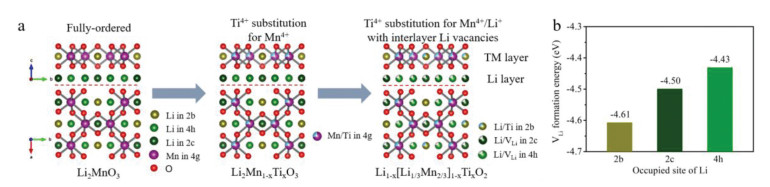
The structure of Li2MnO3 originates from α-NaFeO2 and presents monoclinic structure with space group C2/m [36]. As shown in Fig. 1a (left), the fully ordered Li2MnO3 can be regarded as a TM layered oxide with the chemical formula of Li[Li1/3Mn2/3]O2, and the ordered TM slab is composed of one-third [Li2bO6] and two-thirds [Mn4gO6] octahedrons. We follow the design rules described in Fig. 1a. Ti4+ can efficiently replace Mn4+ on the 4g site because of the similar radius and same valence state of Ti4+ and Mn4+ ions. [Ti4gO6] can inhibit the excessive oxidation of O2− above 4.5 V and improve the cyclic stability of Li2MnO3 structure due to the electrochemical inertness of Ti4+ at high voltage. Based on equivalent state substitution Li2Mn1-xTixO3, we can adjust the ratio of lithium and titanium sources to make Ti4+ substitute Li+ on the 2b site and form Li vacancies in lithium layer, represented by a general stoichiometry of Li1-x[Li1/3Mn2/3]1-xTixO2. The formation of Li vacancies is caused by the unequal-valent substitution between Ti4+ and Li+. And the amount of Li vacancies grows with the increase of the unequal-valent Ti4+-substitution. Introduction of Li vacancy will promote the Li-ion diffusion and activate the reversible redox reaction of Mn3+/4+ during charging/discharging processes, leading to high Li+ storage ability.
Figure 1
Figure 1.
Design of unequal-valent Ti4+-substitution Li1-x[Li1/3Mn2/3]1-xTixO2 with interlayer Li vacancies. (a) The atomic structure evolution from fully ordered Li2MnO3 (left) to equal-valent Ti4+ substituted Li2Mn1-xTixO3 (middle), and then to unequal-valent Ti4+ substituted Li1-x[Li1/3Mn2/3]1-xTixO2 with interlayer vacancies (right). (b) The theoretical calculation results of vacancy (Li) formation energy in Li2MnO3.
However, Li vacancy probably emerges at three sites of 2b, 2c and 4h. The theoretical calculation for each lithium-absence-state indicates that Li vacancy between TM layer is determined by the energetically favorable configuration. According to the simulation results, Li-ions would be preferentially extracted out from lithium layer. For the case of the first Li-ion extraction, the energetically favorable sites are 4h and 2c positions for both pure Li2MnO3 and Ti4+ substituted Li2MnO3. The formation of a Li vacancy in the LiMn2 layer (TM layer) requires 0.18 eV higher energy than that in the lithium layer (Fig. 1b). It suggests that Li+ preferentially anchored at 2b site in TM layer in crystallization process, emerging Li vacancies mainly at 2c and 4h sites in lithium layer [37].
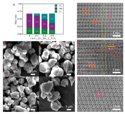
The Li1-x[Li1/3Mn2/3]1-xTixO2 can be easily synthesized by solid-phase reaction. Specifically, the prepared materials are Li0.9[Li1/3Mn2/3]0.9Ti0.1O2, Li0.7[Li1/3Mn2/3]0.7Ti0.3O2, Li0.5[Li1/3 Mn2/3]0.5Ti0.5O2, which can be rewritten as Li0.9[(Li0.9Ti0.1)1/3 (Mn0.9Ti0.1)2/3]O2, Li0.7[(Li0.7Ti0.3)1/3(Mn0.7Ti0.3)2/3]O2, and Li0.5[(Li0.5Ti0.5)1/3(Mn0.5Ti0.5)2/3]O2, respectively. The inductively coupled plasma (ICP) results of these prepared materials are shown in Fig. 2a, which are in good agreement with their chemical formula. The particle morphology was characterized by scanning electron microscopy (SEM). As shown in Figs. 2b-e, all samples have the similar primary particle size of 2–3 µm via solid-phase synthesis. One difference observed from SEM images is that the primary particles of Li0.5[Li1/3Mn2/3]0.5Ti0.5O2 locally agglomerate and form secondary particles (Fig. S1 in Supporting information).
Figure 2
Figure 2.
(a) The ICP results of the prepared Li1-x[Li1/3Mn2/3]1-xTixO2 (x = 0, 0.1, 0.3 and 0.5). The SEM images of (b) Li2MnO3, (c) Li0.9[Li1/3Mn2/3]0.9Ti0.1O2, (d) Li0.7[Li1/3Mn2/3]0.7Ti0.3O2, and (e) Li0.5[Li1/3Mn2/3]0.5Ti0.5O2. The HAABF-STEM images along the [100] zone axis for (f) Li0.9[Li1/3Mn2/3]0.9Ti0.1O2, (g) Li0.7[Li1/3Mn2/3]0.7Ti0.3O2 and [110] zone axis for (h) Li0.5[Li1/3Mn2/3]0.5Ti0.5O2. Yellow dashed boxes in (f, g) indicate the same nine layers in Li0.9[Li1/3Mn2/3]0.9Ti0.1O2 and Li0.7[Li1/3Mn2/3]0.7Ti0.3O2. The ball represents atom in (f-h). Pink: Mn/Ti; Yellow: Li; Red: O.
To confirm the atomic arrangement of the above designed materials, we conducted high-angle annular bright field-scanning transmission electron microscopy (HAABF-STEM). Fig. 2f shows the HAABF-STEM image of Li0.9[Li1/3Mn2/3]0.9Ti0.1O2 along the [100] zone axis. The atomic arrangement of Li0.9[Li1/3Mn2/3]0.9Ti0.1O2 is similar to that of C2/m Li2MnO3 with a layer spacing of 4.8 Å and a repeating sequence of two-atom TM–TM dumbbells in TM layer [36]. A few (002) plane slip is caused by the partial absence of interlayer Li. In the HAABF-STEM image of Li0.7[Li1/3Mn2/3]0.7Ti0.3O2 along the [100] zone axis (Fig. 2g), most regular domains with consecutive superlattice planes and the enclosed domains (red dotted lines) with continuous TM atoms coexist, indicating that the partial Li atoms at 2b sites are replaced by Mn or Ti atoms. In addition, the spacing distance of Li0.7[Li1/3Mn2/3]0.7Ti0.3O2 expands to 4.9 Å. Fig. 2h displays a HAABF-STEM image of Li0.5[Li1/3Mn2/3]0.5Ti0.5O2 along the [110] orientation. Interestingly, the atomic arrangement of Li0.5[Li1/3Mn2/3]0.5Ti0.5O2 likes the structure of a spinel phase [38], which is quite different from the atomic arrangement of Li2MnO3. By the way, the Li0.5[Li1/3Mn2/3]0.5Ti0.5O2 with less Li content can be written as Li[Li1/3Mn2/3Ti]O4 resembling spinel-phase LiMn2O4.
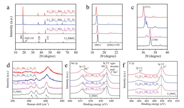
The structures of Li1-x[Li1/3Mn2/3]1-xTixO2 (x = 0, 0.1, 0.3 and 0.5) were detected by X-ray diffractometer (XRD) and Raman spectroscopy measurements. Fig. 3a shows the XRD patterns of Li1-x[Li1/3Mn2/3]1-xTixO2, and all strong diffraction peaks are similar to the layered α-NaFeO2 structure. The 2θ around 20°−22° is attributed to the superlattice plane in monoclinic Li2MnO3, corresponding to (020) and (110) planes [39]. The superlattice peaks become weak with the augment of the x values, which reflects a growing tendency to shape a chaotic arrangement of atoms (Mn/Ti/Li) in TM layer. Finally, the superlattice diffraction peaks disappear in Li0.5[Li1/3Mn2/3]0.5Ti0.5O2 with spinel structure. As shown in the enlarged XRD patterns at 18°−23° (Fig. 3b) and 35°−40° (Fig. 3c), the low-2θ-shift of (001) and (130) diffraction peaks corresponds to the increase of the interplanar spacing, which fits well with the HAABF-STEM images (Figs. 2f and g) and the XRD-rietveld results (Fig. S2 and Table S1 in Supporting information), indicating increased Li vacancies in Li0.9[Li1/3Mn2/3]0.9Ti0.1O2 and Li0.7[Li1/3Mn2/3]0.7Ti0.3O2. Moreover, a new diffraction peak (indexed to (311) plane in spinel LiMn2O4 [40]) is observed in Li0.9[Li1/3Mn2/3]0.9Ti0.1O2 and Li0.7[Li1/3Mn2/3]0.7Ti0.3O2 (Fig. 3c), ascribed to the interlayer Li vacancies.
Figure 3
Figure 3.
(a-c) XRD patterns at different ranges, (d) Raman shifts and (e, f) high-resolution XPS spectra for Mn and Ti of Li1-x[Li1/3Mn2/3]1-xTixO2 (x = 0, 0.1, 0.3 and 0.5).
Raman shift (Fig. 3d) was used to analyze the molecular structures of Li1-x[Li1/3Mn2/3]1-xTixO2, which were difficult to be detected by XRD measurements. In monoclinic Li2MnO3, there are two strong stretching-vibration (A1g and Ag) peaks and a distinct bending-vibration (Eg) peak [41]. Specifically, the Ag peak located at 425 cm−1 stands for a characteristic vibration of monoclinic Li2MnO3 structure [42], while Eg and A1g peaks at 487 cm−1 and 605 cm−1 are associated with the Raman-sensitive layered structure [43]. For spinel-phase Li0.5[Li1/3Mn2/3]0.5Ti0.5O2, the Ag vibration disappears and the A1g peak shifts to 630 cm−1, which is obviously different from the monoclinic Li2MnO3 structure [44]. For Li0.9[Li1/3Mn2/3]0.9Ti0.1O2 and Li0.7[Li1/3Mn2/3]0.7Ti0.3O2, a slight red shift of A1g peak indicates that they tend to transform to spinel phase [45]. However, the stretching Ag vibrations still exist in their molecular structures, illustrating that they still contain the monoclinic structure (like Li2MnO3). The Eg peak gradually weakens because of the variations in the local vibration symmetry of [TMO6] octahedron [46], which mainly generates by the Li vacancies and Ti4+ substitutions.
X-ray photoelectron spectroscopy (XPS) was employed to identify valence states of Mn and Ti in these materials. As shown in Figs. 3e and f, both Mn and Ti present as tetravalence in Li0.9[Li1/3Mn2/3]0.9Ti0.1O2 and Li0.7[Li1/3Mn2/3]0.7Ti0.3O2, which indirectly proves the existence of Li vacancies. By the way, a right-shoulder peak visualizes at the Mn 2p3/2 spectra of Li0.5[Li1/3Mn2/3]0.5Ti0.5O2, indicating the co-existence of Mn4+ and Mn3+ in spinel-phase Li0.5[Li1/3Mn2/3]0.5Ti0.5O2.
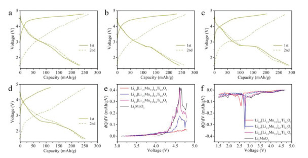
The charge/discharge measurements of Li1-x[Li1/3Mn2/3]1-xTixO2 (x = 0, 0.1, 0.3 and 0.5) were conducted to explore the influence of the unequal-valent Ti4+-substitution with interlayer Li vacancies on the electrochemical performance. Figs. 4a-d display the charge/discharge curves of the above cathode materials for the first two cycles at a current density of 10 mA/g. To facilitate comparison, their initial charge/discharge curves are placed together in Fig. S3 (Supporting information). The initial charge capacities of Li2MnO3 (247 mAh/g), Li0.9[Li1/3Mn2/3]0.9Ti0.1O2 (231 mAh/g) and Li0.7[Li1/3Mn2/3]0.7Ti0.3O2 (205 mAh/g) are mainly contributed by the oxidation of O2− above 4.5 V. With the increase of unequal-valent Ti4+-substitution, the decrease of the charging capacity is ascribed to the effort of Ti4+ substitution, which inhibits the lattice oxygen oxidation at high voltages. Meanwhile, the slightly increasing capacity between 3.5–4.5 V is caused by the oxidation of Mn3+. By contrast, the spinel-phase Li0.5[Li1/3Mn2/3]0.5Ti0.5O2 cathode exhibits much lower first charge capacity (117 mAh/g) than other samples. The initial discharge capacities of Li2MnO3, Li0.9[Li1/3Mn2/3]0.9Ti0.1O2, Li0.7[Li1/3Mn2/3]0.7Ti0.3O2, and Li0.5[Li1/3Mn2/3]0.5Ti0.5O2 cathodes are 229, 241, 290 and 252 mAh/g, respectively. Compared with Li2MnO3, the Ti4+-substituted samples present a new plateau, located at around 2.8 V in Li0.9[Li1/3Mn2/3]0.9Ti0.1O2 and Li0.7[Li1/3Mn2/3]0.7Ti0.3O2, but 2.6 V in spinel-phase Li0.5[Li1/3Mn2/3]0.5Ti0.5O2. This unique lithiation process is related to the reduction of Mn4+ accompanying with the intercalation of Li+ [18], which benefits from interlayer Li vacancies. The plateau related to Mn3+/4+ redox extends with the unequal-valent Ti4+ substitution, increasing until the phase transferred to spinel after Ti4+ substituted Li2MnO3. The long plateau means a deep reduction reaction of Mn3+/4+, indicating that unequal-valent Ti4+-substitution and interlayer Li vacancies can increase the capacity of the sample. And the voltages associated with the increased capacities of Li0.9[Li1/3Mn2/3]0.9Ti0.1O2 and Li0.7[Li1/3Mn2/3]0.7Ti0.3O2 are completely retained in the second cycle, indicating good reversibility of Mn3+/4+ redox. The corresponding differential capacity versus voltage (dQ/dV) plots of Li1-x[Li1/3Mn2/3]1-xTixO2 (x = 0, 0.1, 0.3 and 0.5) exhibit similar electrochemical changes to their charge/discharge curves. Fig. 4e shows initial dQ/dV plots of charging process, the oxygen dimerization peak weakens with the increase of x value and finally disappears in spinel-phase Li0.5[Li1/3Mn2/3]0.5Ti0.5O2. The paired dQ/dV plots during discharge are shown in Fig. 4f, a sharp peak emerges around 2.8 V after unequal-valent Ti4+ substituting, which corresponds to the Mn3+/4+ redox activated by Ti4+ substitution and interlayer Li vacancies. The sharpest reduction peak appears in Li0.7[Li1/3Mn2/3]0.7Ti0.3O2, and the reduction peak shifts to 2.6 V in spinel-phase Li0.5[Li1/3Mn2/3]0.5Ti0.5O2.
Figure 4
Figure 4.
First-two cycles charge/discharge curves of (a) Li2MnO3, (b) Li0.9[Li1/3Mn2/3]0.9Ti0.1O2, (c) Li0.7[Li1/3Mn2/3]0.7Ti0.3O2, and (d) Li0.5[Li1/3Mn2/3]0.5Ti0.5O2 at 10 mA/g. The corresponding dQ/dV plots of (e) charging process and (f) discharging process related to the first cycle.
To further understand the contribution of interlayer Li vacancies caused by unequal-valent Ti4+-substitution to Li-ion storage, we compare the electrochemical characteristics of equal-valent Ti4+ substituted Li2Mn1-xTixO3, including Li2Mn0.9Ti0.1O3 and Li2Mn0.7Ti0.3O3, where Ti4+ only replaces Mn4+ without Li vacancy formation. The XRD patterns of Li2Mn1-xTixO3 (x = 0, 0.1 and 0.3) (Fig. S4 in Supporting information) manifest high similar structure. Fig. S5 (Supporting information) shows their charge/discharge curves at 10 mA/g. The simply equal-valent Ti4+-substitution (Ti substituted Mn) can also activate Mn3+/4+ redox, but reversibility is worse than that of unequal-valent Ti4+-substituted Li2MnO3, which is our designed strategy to achieve Ti4+-substitution and build interlayer Li vacancies. The Li2Mn0.9Ti0.1O3 and Li2Mn0.7Ti0.3O3 show the lower Coulombic efficiency (CE) than that of Li0.9[Li1/3Mn2/3]0.9Ti0.1O2 and Li0.7[Li1/3Mn2/3]0.7Ti0.3O2 in the second cycle, indicating that interlayer Li vacancies can also improve the stability of electrochemical process. Compared with the designed unequal-valent Ti4+-substitution cathodes, there are no sharp peaks in the dQ/dV plots of equal-valent Ti4+ substituted Li2Mn1-xTixO3 during the discharge process (Fig. S6 in Supporting infromation), demonstrating that the activation of Mn3+/4+ redox is mainly contributed by the unequal substitution with interlayer Li vacancies.
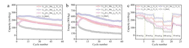
The cycling performance of Li2MnO3 based cathodes was measured at a current density of 50 mA/g. As shown in Fig. 5a, the initial capacities of Li0.5[Li1/3Mn2/3]0.5Ti0.5O2, Li0.7[Li1/3Mn2/3]0.7Ti0.3O2, Li0.9[Li1/3Mn2/3]0.9Ti0.1O2, and Li2MnO3 cathodes are 220, 242, 143 and 167 mAh/g, respectively, and their capacity retention after 60 cycles are 59%, 83%, 84%, and 39%, respectively. Li2Mn0.9Ti0.1O3 and Li2Mn0.7Ti0.3O3 cathodes have 139 and 143 mAh/g capacities with 47% and 61% retentions at 50 mA/g after 60 cycles (Fig. S7 in Supporting information). Among these cathodes, Li0.7[Li1/3Mn2/3]0.7Ti0.3O2 cathode shows the highest CE in 60 cycles, especially in the first five cycles (Fig. S8 in Supporting information). In view of these results, the unequal-valent Ti4+-substitution with interlayer Li vacancies building and Ti4+-substitution can increase capacities and improve cyclic stability of Li2MnO3 based cathodes. In addition, Li0.7[Li1/3Mn2/3]0.7Ti0.3O2 cathode delivers a high energy of 661 Wh/kg (457 Wh/kg for Li2MnO3) and a residual energy of 447 Wh/kg (144 Wh/kg for Li2MnO3) after 60 cycles (Fig. 5b and Fig. S9 in Supporting information). The rate ability of Li1-x[Li1/3Mn2/3]1-xTixO2 (x = 0, 0.1, 0.3 and 0.5) cathodes also was investigated. The rate performance of Li2MnO3 cathode is enhanced with the appropriate unequal-valent Ti4+-substitution (Fig. 5c), implying that Ti4+ substitution and interlayer Li vacancies induce a thermodynamically fast Li-ion intercalation process in the Li2MnO3 structural phase.
Figure 5
Figure 5.
(a) Capacity, (b) energy density, and (c) rate performance of the Li1-x[Li1/3Mn2/3]1-xTixO2 (x = 0, 0.1, 0.3 and 0.5) at a current density of 50 mA/g.
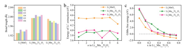
DFT calculations (Fig. 6) in terms of structural relaxation and total energy were carried out to further understand the improved LIBs performance of the modified Li2MnO3 cathodes. The simplified model of Ti replacing Mn is adopted to show the effect of Ti4+ substitution in Li2MnO3. Calculation results show that the average length of the TM—O bond increased compared to the length of the Mn—O bond in Li2MnO3 after Ti4+ substitution (Li2Mn0.9Ti0.1O3 and Li2Mn0.7Ti0.3O3) (Fig. 6a). O1-O6 stand for six TM—O bonds in [TMO6] octahedron as shown in Fig. S10 (Supporting information). In addition, the substitution of Ti4+ pushes the surrounding atoms away from the [TiO6] octahedron, which is consistent with the Mo doped Li2MnO3 configuration [47], indicating that the surrounding structure is loose. For the Li2Mn0.9Ti0.1O3 and Li2Mn0.7Ti0.3O3 structures, the calculated supercell volume will increase from 413.5 Å3 to 418.0 Å3 and 417.7 Å3, respectively, as listed in Table S2 (Supporting information). According to Gao et al. [47], the expanded lattice due to Ti doping can facilitate the Li-ion diffusion. The correlations between the delithiation energy and the lithium content under different substitution conditions are shown in Fig. 6b, where n represents the number of Li-ions extraction. With respect to the pristine Li2MnO3, the delithiation energy is reduced by 0.58–0.75 eV after the Ti4+ substitution, indicating that the electrochemical activity of Li2MnO3 is enhanced by the incorporation of Ti4+.
Figure 6
Figure 6.
(a) Calculated bond length of TM-O between oxygen and transition metals in Li2MnO3, Li2Mn0.9Ti0.1O3 and Li2Mn0.7Ti0.3O3, respectively. (b) Calculated formation energies of Li vacancies in Li2MnO3, Li2Mn0.9Ti0.1O3 and Li2Mn0.7Ti0.3O3. (c) Calculated reaction Gibbs free energy of O2 release from the lattice of Li2-xMn1-yTiyO3, with x = 0, 0.125, 0.25, 0.375, 0.5, 0.625, 0.75, and y = 0, 0.1, 0.3.
Furthermore, we evaluate the O2 release reaction to reflect the stability of the oxygen sublattice in Ti4+ substituted Li2MnO3 using DFT calculations. Considering the entropy of gas phase O2 under standard states (−TΔS = −0.63 eV) [48], the Gibbs free energy ΔG can be obtained. Fig. 6c shows the reaction Gibbs free energy of O2 release from the lattice of Li2-xMn1-yTiyO3. Upon delithiation, the Gibbs free energies decrease monotonically, indicating that the lattice stability of Li2-xMn1-yTiyO3 will decrease with increasing amount of delithiation. In the case of unsubstituted Li2MnO3, the formation Gibbs energy is below zero when x > 0.4, indicating that the oxygen release reaction would occur spontaneously. After Ti doping, the spontaneous oxygen release will delay to x > 0.5 and x > 0.6 for Li2Mn0.7Ti0.3O3 and Li2Mn0.9Ti0.1O3, respectively, suggesting that the O2 release reaction is suppressed and consequently the structural stability is improved.
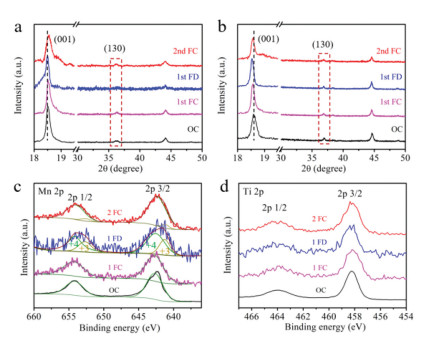
We carried out ex-situ XRD measurement to detect the structural evolution of Li0.7[Li1/3Mn2/3]0.7Ti0.3O2 and Li2MnO3 at open circuit (OC), full charge (FC) and full discharge (FD) states under a current density of 10 mA/g. The ex-situ XRD patterns are shown in Figs. 7a and b. At the first FC state, the diffraction peak of (001) slightly shifts to high degree (clearly shown in Fig. S11a in Supporting information) in Li0.7[Li1/3Mn2/3]0.7Ti0.3O2 due to the lattice oxygen oxidation with Li+ removing from TM layer. On contrast, the (001) diffraction peak of Li2MnO3 shifts to low degree at initial FC state (Fig. S11b in Supporting information), indicating the enlarging of the interlayer spacing caused by the excessive lattice oxygen dimerization and the oxygen release, which represents an unstable structure during the charge process. At the initial FD state, the interlayer spacing of both Li0.7[Li1/3Mn2/3]0.7Ti0.3O2 and Li2MnO3 becomes large due to Li+ intercalation, which is a typical lithiation phenomenon in layered oxide cathodes. The (001) diffraction peak of Li0.7[Li1/3Mn2/3]0.7Ti0.3O2 moves back, which means that Li0.7[Li1/3Mn2/3]0.7Ti0.3O2 with enlarged interlayer spacing can alleviate the strain perpendicular to z axis during Li+ intercalation. It avoids the lattice collapse in layered structure. Differently, the (130) diffraction peak of FD state in Li0.7[Li1/3Mn2/3]0.7Ti0.3O2 disappears, which means that the Mn4+ reduction induced extra embedded Li+ are not arranged as regularly as Li+ in Li2MnO3. The extra Li+ intercalation exhibits a good reversible behavior as the (130) diffraction peak reappears in Li0.7[Li1/3Mn2/3]0.7Ti0.3O2 electrode at the second FC state.
Figure 7
Figure 7.Ex-situ XRD patterns of (a) Li0.7[Li1/3Mn2/3]0.7Ti0.3O2 and (b) Li2MnO3 cathodes. And ex-situ XPS spectra of the Li0.7[Li1/3Mn2/3]0.7Ti0.3O2 electrode for (c) Mn and (d) Ti elements.
Furthermore, the ex-situ XPS tests were taken out to analyze the charge compensation mechanisms and identify the source of the increased capacity. Fig. 7c shows the ex-situ XPS spectra of Mn element in Li0.7[Li1/3Mn2/3]0.7Ti0.3O2 at different states. Mn4+ is not oxidized to a high valence state during the charge process, while it is partially reduced to Mn3+ as expected with a Mn4+/Mn3+ ions ratio of 2.2 (closing to the Li/VLi ratio of 0.7/0.3 in lithium layer) in the first FD state. It can further confirm that the increased capacity is originate from the Mn3+/4+ redox reaction. Subsequently, almost all of the Mn3+ are oxidized to Mn4+ at the second FC state, representing a good reversibility of the Mn3+/4+ redox. The ex-situ XPS spectra of Ti element in Li0.7[Li1/3Mn2/3]0.7Ti0.3O2 are shown in Fig. 7d. Ti4+ always exists without charge transfer, further verifying the stable and inert of titanium in cathodes at high voltages, which is beneficial to improve the electrochemical stability of unequal-valent Ti4+-substituted Li2MnO3 cathodes.
In summary, a series of unequal-valent Ti4+-substituted Li2MnO3 (Li1-x[Li1/3Mn2/3]1-xTixO2, x = 0, 0.1, 0.3 and 0.5) samples are successfully designed. After unequal-valent Ti4+-substitution, the interlayer Li vacancies are built. Our strategy can stabilize the structure and improve the cycling performance of Li2MnO3-based cathodes. In particular, the substitution of Ti4+ for Li+ in TM layer leads to the formation of Li vacancies in lithium layer, which is in good agreement with the DFT calculation results that the Li vacancies preferentially existed at 2c and 4h sites (lithium layer) in Li2MnO3. The interlayer Li vacancies facilitate the Li-ion transport and greatly increase the capacity by activating the reversible Mn3+/4+ redox during the charge/discharge processes. In addition, DFT calculations simultaneously confirm that the Ti4+ substituted Li2MnO3 can promote Li-ion diffusion and inhibit the oxidation of O2− above 4.5 V. The as-designed Li0.7[Li1/3Mn2/3]0.7Ti0.3O2 cathode displays a high capacity of 290 mAh/g, stable cycling and enhanced rate performance. Therefore, the unequal-valent Ti4+-substitution is an efficient strategy for improving the electrochemical performance of Li2MnO3.
Declaration of competing interest
There are no conflicts to declare.
Acknowledgments
This work was financially supported by the National Natural Science Foundation of China (Nos. 51972258 and 22109186) and Open Fund by Sanya Science and Education Innovation Park of Wuhan University of Technology (No. 2021KF0021). Y. Sun is supported by 21C Innovation Laboratory, Contemporary Amperex Technology Ltd. by Project No. 21C-OP-202002.
Supplementary materials
Supplementary material associated with this article can be found, in the online version, at doi:10.1016/j.cclet.2022.05.008.
[1]
K. Shen, Z. Wang, Y. Ying, et al., Adv. Energy Mater. 9 (2019) 1900260. doi: 10.1002/aenm.201900260
Y. Gao, J. Ma, X. Wang, et al., J. Mater. Chem. A 2 (2014) 4811–4818. doi: 10.1039/c3ta15236g
[48]
J.S. Hummelshøj, J. Blomqvist, S. Datta, et al., J. Chem. Phys. 132 (2010) 071101. doi: 10.1063/1.3298994
Figure 1
Design of unequal-valent Ti4+-substitution Li1-x[Li1/3Mn2/3]1-xTixO2 with interlayer Li vacancies. (a) The atomic structure evolution from fully ordered Li2MnO3 (left) to equal-valent Ti4+ substituted Li2Mn1-xTixO3 (middle), and then to unequal-valent Ti4+ substituted Li1-x[Li1/3Mn2/3]1-xTixO2 with interlayer vacancies (right). (b) The theoretical calculation results of vacancy (Li) formation energy in Li2MnO3.
Figure 2
(a) The ICP results of the prepared Li1-x[Li1/3Mn2/3]1-xTixO2 (x = 0, 0.1, 0.3 and 0.5). The SEM images of (b) Li2MnO3, (c) Li0.9[Li1/3Mn2/3]0.9Ti0.1O2, (d) Li0.7[Li1/3Mn2/3]0.7Ti0.3O2, and (e) Li0.5[Li1/3Mn2/3]0.5Ti0.5O2. The HAABF-STEM images along the [100] zone axis for (f) Li0.9[Li1/3Mn2/3]0.9Ti0.1O2, (g) Li0.7[Li1/3Mn2/3]0.7Ti0.3O2 and [110] zone axis for (h) Li0.5[Li1/3Mn2/3]0.5Ti0.5O2. Yellow dashed boxes in (f, g) indicate the same nine layers in Li0.9[Li1/3Mn2/3]0.9Ti0.1O2 and Li0.7[Li1/3Mn2/3]0.7Ti0.3O2. The ball represents atom in (f-h). Pink: Mn/Ti; Yellow: Li; Red: O.
Figure 3
(a-c) XRD patterns at different ranges, (d) Raman shifts and (e, f) high-resolution XPS spectra for Mn and Ti of Li1-x[Li1/3Mn2/3]1-xTixO2 (x = 0, 0.1, 0.3 and 0.5).
Figure 4
First-two cycles charge/discharge curves of (a) Li2MnO3, (b) Li0.9[Li1/3Mn2/3]0.9Ti0.1O2, (c) Li0.7[Li1/3Mn2/3]0.7Ti0.3O2, and (d) Li0.5[Li1/3Mn2/3]0.5Ti0.5O2 at 10 mA/g. The corresponding dQ/dV plots of (e) charging process and (f) discharging process related to the first cycle.
Figure 5
(a) Capacity, (b) energy density, and (c) rate performance of the Li1-x[Li1/3Mn2/3]1-xTixO2 (x = 0, 0.1, 0.3 and 0.5) at a current density of 50 mA/g.
Figure 6
(a) Calculated bond length of TM-O between oxygen and transition metals in Li2MnO3, Li2Mn0.9Ti0.1O3 and Li2Mn0.7Ti0.3O3, respectively. (b) Calculated formation energies of Li vacancies in Li2MnO3, Li2Mn0.9Ti0.1O3 and Li2Mn0.7Ti0.3O3. (c) Calculated reaction Gibbs free energy of O2 release from the lattice of Li2-xMn1-yTiyO3, with x = 0, 0.125, 0.25, 0.375, 0.5, 0.625, 0.75, and y = 0, 0.1, 0.3.
Figure 7Ex-situ XRD patterns of (a) Li0.7[Li1/3Mn2/3]0.7Ti0.3O2 and (b) Li2MnO3 cathodes. And ex-situ XPS spectra of the Li0.7[Li1/3Mn2/3]0.7Ti0.3O2 electrode for (c) Mn and (d) Ti elements.

 DownLoad:

 下载:
下载:


