Citation:
Xin-Yu Zhang, Wen-Li Yu, Jie Zhao, Jia-Yu Fu, Bin Dong, Fu-Li Wang, Jian-Feng Yu, Chen-Guang Liu, Yong-Ming Chai. Self-supported FexNi1-xMoO4 with synergistic morphology and composition for efficient overall water splitting at large current density[J]. Chinese Chemical Letters,
2023, 34(2): 107422.
doi:
10.1016/j.cclet.2022.04.020
Self-supported FexNi1-xMoO4 with synergistic morphology and composition for efficient overall water splitting at large current density
English
Self-supported FexNi1-xMoO4 with synergistic morphology and composition for efficient overall water splitting at large current density
State Key Laboratory of Heavy Oil Processing, College of Chemistry and Chemical Engineering, China University of Petroleum (East China), Qingdao 266580, China
Received Date:
18 January 2022 Accepted Date:
08 April 2022 Revised Date:
12 February 2022 Available Online:
15 February 2023
Abstract:
Developing the high activity, low cost and robust large-current-density-based electrocatalysts is of great significance for the industrial electrolytic water splitting. However, the current range of most reported materials is small, which makes it difficult for them to play their roles in practical applications. Here, a self-supported amorphous FexNi1-xMoO4/IF treated with ammonium fluoride (AF0.1-FNMO/IF) is synthesized by one-step hydrothermal method. With the help of NH4F, AF0.1-FNMO/IF exhibits a vertically cross-linked nanosheet with spherical structure. Electrochemical measurement shows that AF0.1-FNMO/IF affords a large current density ordeal and only need low overpotentials of 289 and 345 mV to reach a current response of 500 mA/cm2 for oxygen evolution reaction and hydrogen evolution reaction, respectively, together with long-time stability (both at 500, 1000 and 2000 mA/cm2) in 1.0 mol/L KOH solution. Using it as bifunctional catalyst for overall water splitting, the current densities of 100, 500, 1000 and 1500 mA/cm2 are achieved at a cell voltage of 1.71, 1.88, 1.94 and 1.97 V with excellent durability, which is much better than that of most published electrodes. The work provides valuable insight for designing higher activity nickel iron-based molybdate catalysts with large current density.
The massive use of fossil fuel makes the carbon emissions continue to increase, and global environmental change encourages people to urgently develop the renewable energy [1-3]. Hydrogen energy has been considered as the most ideal carrier due to its many advantages including high energy density, pollution-free and renewability [4-7]. At present, the greenest method to produce the hydrogen is electro-catalytic water splitting, which decomposes the water molecule into hydrogen and oxygen and thus maximizing the utilization of water resources [8-10]. However, the key factor that restricting the industrial application of electrolytic water is high electricity consumption, which is caused by the large overpotential on the surface of electrode [11-14]. Therefore, it is vital to explore the electrocatalyst to promote the electrolytic water process while reducing the electricity price. Especially for bifunctional eletrocatalysts, which can be both used as cathode and anode materials and thus reducing the cost of sample preparation [15-18].
Recently, enormous state-of-art transition metal compounds have been developed as bifunctional eletrocatalysts for overall water splitting [19-23]. And iron, nickel or cobalt based molybdates are proved to have high inherent activity for both oxygen evolution reaction (OER) and hydrogen evolution reaction (HER), which are expected to be a promising candidate for replacing the commercial noble metal-based nanomaterials, such as Pt/C and RuO2 [24-27]. Among them, bimetallic molybdates are more attractive since the synergistic effect between different metal species. Especially for the catalyst with amorphous phase structure, the long-range disorderly and random orientation structure endows it large flexibility, thus promoting the adsorption of reactants and the conduct of electrocatalytic reaction [28-30]. In addition, heteroatomic doping (such as Ce, F, S and P) can further modify the electronic structure of the catalyst on the basis of amorphous, so as to optimize its water electrolysis performance [31-33]. However, most of reported eletrocatalysts of this type are in a powder state. During the test process, they usually rely on organic binder to attach the surface of electrode and thus showing a low current range (≤ 100 mA/cm2), which makes it difficult to meet actual industrial application (≥ 400 mA/cm2) [34]. Therefore, it is still a challenge to investigate the molybdate eletrocatalysts that can be operated under a large current density.
In order to meet the practical industrial production requirements, the large current-based bifunctional catalyst prepared should conform the following requirements as far as possible: (i) high intrinsic HER and OER performance; (ii) a self-supported structure that does not depend on binder; (iii) fast mass transport and charge transfer property; (iv) timely exchange the reactants and products; (v) low preparation cost and (vi) long-time stability in highly corrosive electrolyte environment [35-37]. In addition to the above-mentioned conditions, it is also vital to have a suitable substrate (such as iron foam) with three-dimensional spatial structure and strong mechanical performance. When providing a large growth area for the active site, it can also prevent the collapse of the whole system, thus further improving the overall performance of the catalyst [38-40].
Additionally, the morphology controlling agents play a key role in the synthesis and exploration of morphology-dependent electrocatalysts, such as NH4F [41-43]. On the one hand, the fluoride ions generated by dissociation can coordinate strongly with some metal cations, which plays a role in reducing the release speed of metal ions and thus further slows down the nucleation rate of target catalyst. On the other hand, by hydrolysis of ammonium fluoride, hydrogen ions are produced and that make the solution in an acidic state. Then the H+ could react with the substrate to form more active area for growth of the main materials, which can not only exactly achieve the doping of F, but also promote the compact adhesion between architectures and substrate [44, 45].
Inspirited by the above analysis, herein, we have developed a bimetallic Fe-Ni molybdate as the highly efficient bifunctional catalyst with one-step hydrothermal method. By means of the regulation of ammonium fluoride, the obtained AF0.1-FNMO/IF shows the robust cross-linked nanosheet morphology with spherical structure. In 1.0 mol/L KOH solution, it displays superior activities and requires overpotentials of 289 mV (OER) and 345 mV (HER) to afford a high current density of 500 mA/cm2. Moreover, AF0.1-FNMO/IF bifunctional eletrocatalysts-based water splitting cell has also shown a low voltage of 1.88 V to drive the 500 mA/cm2, which is superior to that of most reported samples.
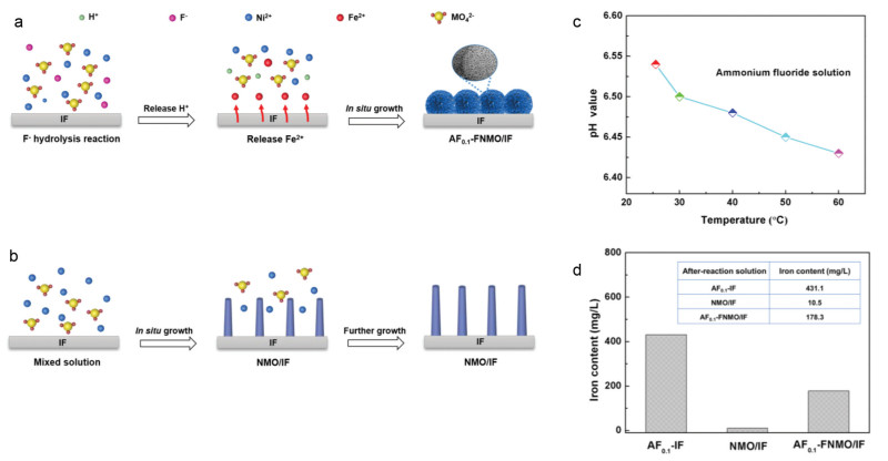
As shown in Figs. 1a and b, the electrocatalysts of AF0.1-FNMO/IF and NMO/IF are mainly synthesized by the one-step hydrothermal method. Compared with NMO/IF, the mixed solution of prepared AF0.1-FNMO/IF is supplemented with ammonium fluoride reagent. It can be seen that the nanostructure of NMO/IF is in a nanorod state. While the morphology of AF0.1-FNMO/IF is sphere-like nanosheets, which indicates that the NH4F plays a decisive role in the preparation of it. Specifically, there will be a bidirectional hydrolysis between fluoride and ammonium ions in the solution that can make the whole system in an acidic condition.
Figure 1
Figure 1.
(a) Schematic illustration showing the growth process of AF0.1-FNMO/IF and (b) NMO/IF. (c) The pH value of 0.1 g NH4F in 40 mL aqueous solution varies with temperature. (d) The amount of iron in the solution after the hydrothermal reaction for AF0.1-IF, NMO/IF and AF0.1-FNMO/IF.
With the increase of temperature, the acidity becomes stronger (Fig. 1c) and the resulting hydrogen ions can react with the iron foam thus releasing Fe2+. Due to the uniform mixing of nickel-iron ions, it is difficult for molybdate to grow along with a certain crystal surface during the formation of NiMoO4 and FeMoO4, which leads to an amorphous state. However, the phenomenon described above is not reflected in the synthesis process of NMO/IF catalyst. Where there is few free Fe2+, and the MO42− can only react with nickel to form the NiMoO4/IF with the specific crystalline structure.
To verify the above analysis, the concentration of iron ions in each group after hydrothermal reaction was tested with a Thermo Fischer Scientic iCAP-QC instrument. As shown in Fig. 1d, the amounts of iron in the solution is 431.1 mg/L for AF0.1-/IF. After combining with Ni2+, Fe2+ and MO42− to form AF0.1-FNMO/IF, the iron ion concentration becomes 178.3 mg/L, which indicates that the missing part is used to construct the amorphous nanosheet. While for NMO/IF, its value is only 10.5 mg/L and it is difficult to participate in the formation of precipitation FeMoO4 when there are large Ni2+.
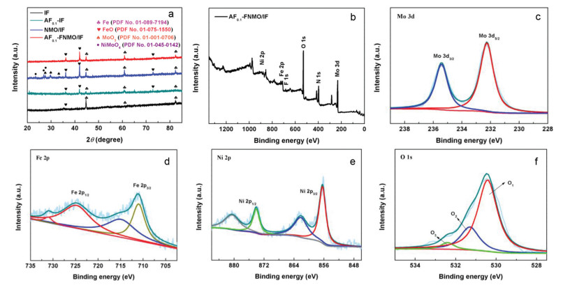
The structural characterization of as-prepared IF, AF0.1-IF, NMO/IF and AF0.1-FNMO/IF is probed by X-ray diffraction (XRD) study. As shown in Fig. 2a, the IF exhibits four diffraction peaks, where the peaks at 44.67°, 65.02° and 82.33° are corresponding to Fe (PDF No. 01-089-7194) and the peak at 36.12° can be indexed to FeO species (PDF No. 01-075-1550), which may be due to oxidation of surface iron.
Figure 2
Figure 2.
(a) XRD patterns of AF0.1-FNMO/IF, (b) XPS spectrum survey of AF0.1-FNMO/IF in the (c) Mo 3d, (d) Fe 2p, (e) Ni 2p and (f) O 1s regions.
After being treated with ammonium fluoride, AF0.1-IF shows two more peaks at 41.92° and 72.81° than iron foam, which are also the characteristic peaks of FeO. Compared with AF0.1-IF, NMO/IF has two new types of diffraction position at 23.35°, 25.58°, 27.48° and 23.39°, 27.41°, 29.75°, which could be indexed to the NiMoO4 (PDF No. 00-045-0142) and MoO3 (PDF No. 00-001-0706), respectively. Here, the MoO3 may originate from the decomposition of molybdate during hydrothermal processes. For AF0.1-FNMO/IF, it also has only the peak of Fe and FeO species, indicating an amorphous state. This could be probably attributed to the uniform distribution of nickel and iron ions during the formation of precipitation and thus making it impossible for NiMoO4 or FeMoO4 to grow in crystal direction independently.
Further, X-ray photoelectron spectroscopy (XPS) has been employed to investigate the chemical environment and valence state of all elements. Fig. 2b is a whole spectrum survey of AF0.1-FNMO/IF, which contains Mo, Fe, Ni, O, N and F. In the Mo 3d XPS spectrum (Fig. 2c), it appears at 235.4 and 232.2 eV with a binding energy difference of ~3.2 eV, that can be assigned to Mo 3d3/2 and Mo 3d5/2. Compared with the Mo 3d spectrum of pure NiMoO4 (Figs. S2a and d in Supporting information), there is no obvious shift, which is characteristic of the Mo6+ oxidation state in NiMoO4 and AF0.1-FNMO/IF [46]. For the Fe 2p spectrum of AF0.1-FNMO/IF (Fig. 2d), it is well de-convoluted into two set of peaks associated with Fe2+ signals (724.7 and 711.4 eV) and the satellite signals (731.2 and 716.1 eV) [47]. Where the energy difference between AF0.1-FNMO/IF and NMO/IF indicates the presence of iron on the surface of AF0.1-FNMO/IF (Figs. S2b and e in Supporting information). For Ni 2p shown in Fig. 2e, it has strong Ni 2p1/2 and Ni 2p3/2 peaks at 874.2 eV and 856.4 eV, respectively, as well as two satellites at 880.6 eV and 862.3 eV. Meanwhile, it is worth noting that the Ni 2p peaks have a blue shift in comparison with those of pure NiMoO4, which may be due to the introduction of iron leading to the redistribution of electrons (Figs. S2c and f in Supporting information) [27]. In addition, the O 1s spectra can be divided into three characteristic peaks at 529.9, 530.6, and 531.5 eV (Fig. 2f). The observed peaks are due to the metal-oxygen bond bound to iron or molybdenum (529.9 eV), surface-adsorbed hydroxyl groups (530.6 eV) and adsorbed water molecules (531-534 eV), respectively [48]. Meanwhile, the XPS data of fluorine has also been detected at 684.4 eV, which may be residual on the sample surface during the reaction (Fig. S3 in Supporting information) [49].
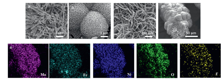
The detailed structure and morphology of IF, AF0.1-IF, NMO/IF and AF0.1-FNMO/IF have been observed by scanning electronic microscope (SEM) techniques in Figs. S4 and S5 (Supporting information) and Fig. 3. As shown in Fig. S4a, the surface of pure iron foam is relatively smooth. When it is treated with 0.1 g ammonium fluoride, the iron foam has been etched by hydrogen ions generated by hydrolysis and the smooth morphology becomes the larger nanosheets (Fig. S4b). Fig. 3a is the SEM image of NMO/IF, which has a rod-like structure with an average radial length of 1-2 micron. Without competition of Fe2+, NiMoO4 can grow freely along with the specific crystal orientation. More interestingly, when the mixed system contains ammonium fluoride, the morphology of the electrode changes to nano-flower with spherical structure (Fig. 3b). At the higher magnification, it shows a vertically growing nanosheet with the state of the cross link (Fig. 3c), which is conducive to the proton transport and the timely elimination of bubbles. To further optimize the growth state of the nickel-iron molybdate nanosheets, different contents of ammonium fluoride are considered. It can be seen that with the increase of ammonium fluoride content, the length of the nanosheet gradually decreases until becoming to the sparse dispersed nanospheres (Fig. S5 Supporting information). And the iron foam treated with 0.1 g NH4F is right in the middle of those two and implies a better catalytic performance (Fig. S6 in Supporting information). Meanwhile, the SEM mapping (Figs. 3d and e) and energy dispersive spectroscopy (EDS data) (Table S1 in Supporting information) for AF0.1-FNMO/IF are fully testified the uniform distribution of Mo, Fe, Ni, O and F elements, where the corresponding atomic percentages are 10.87%, 6.57%, 13.00%, 69.27% and 0.28%. In addition, the high-resolution transmission electron microscopy (HRTEM) images further prove that the amorphous state of AF0.1-FNMO/IF catalyst. Where the nickel-iron molybdate complex exhibits an obvious nanosheet structure (Figs. S7a and b in Supporting information). At a size of five nanometers, it rarely shows the distinct lattice fringe. And in some local areas, the fringe is intricate, which indicates that there are more competitive reactions in the growth of different crystals (Figs. S7c and d in Supporting information). This result is consistent with the information available from XRD and SEM technologies.
Figure 3
Figure 3.
SEM images of (a) NMO/IF, (b, c) AF0.1-FNMO/IF, (d, e) SEM mapping of AF0.1-FNMO/IF.
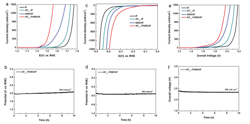
The electrocatalytic performance of AF0.1-FNMO/IF catalyst toward OER has been first investigated by the IR-corrected polarization curves in 1 mol/L KOH electrolyte. In contrast, other materials are also tested in the same condition, which contains IF, AF0.1-IF and NMO/IF. As shown in Fig. 4a, all samples exhibit significant oxygen evolution properties, and among them AF0.1-FNMO/IF gives the best catalytic activity. To deliver a current density of 100 mA/cm2, the overpotential (η100) for AF0.1-FNMO/IF is only need 240 mV. This value is far below the IF (460 mV), AF0.1-IF (404 mV) and NMO/IF (287 mV). Furthermore, AF0.1-FNMO/IF can afford the large-current-density test and require low overpotentials merely of 289, 314 and 330 mV to reach 500, 1000 and 1500 mA/cm2, respectively, which makes it great potential in actual industrial electrolysis of water (Fig. S8a in Supporting information). Fig. S8b (Supporting information) displays the Tafel plots obtained from the reverse LSV curves by CV method (1.1–1.7 V vs. RHE) (Fig. S8c in Supporting information). Where a small value of 31.2 mV/dec corresponds to the AF0.1-FNMO/IF, which is lower than that of IF (71.8 mV/dec), AF0.1-IF (70.7 mV/dec) and NMO/IF (36.5 mV/dec), suggesting a superior reaction kinetic toward OER. Moreover, the electrochemical impedance spectrum (EIS) is measured to explore the kinetics performance of the electrode under the oxygen evolution reaction process and Fig. S8c (Supporting information) shows the Nyquist plots of them. It can be seen that the charge transfer resistance (Rct) order is: AF0.1-FNMO/IF < NMO/IF < AF0.1-IF < IF, indicating the faster charge transfer and reaction kinetics of AF0.1-FNMO/IF. Apart from above data, the stability property is another vital parameter that affects its practical application. And the catalytic stability of the AF0.1-FNMO/IF has been explored using chronoamperometry (CP) technique at a constant current. As shown in Fig. 4b, the V-t curve recorded at 500 mA/cm2 in 1.0 mol/L KOH electrolyte performs a steady state and maintain their current density over 10 h. Even though at higher current densities, namely, 1000 and 2000 mA/cm2 with small potential fluctuations, the AF0.1-FNMO/IF also has long-term stability (Fig. S8d in Supporting information). It is worth noting that the voltage required by LSV in Fig. 4a is different from CP when the current density is same. This phenomenon is normal and that is mainly caused by the existence of IR compensation in polarization curve test. Here, the high performance and great stability of AF0.1-FNMO/IF under large current is more likely derived from the self-supported vertically growing with cross-linked nanosheet structure that can facilitate the transmission of protons and diffusion of oxygen gas. On the one hand, the direct contact between the catalyst and the IF substrate can greatly accelerate the electron transfer; on the other hand, the uniform growth of nickel-iron molybdate can further improve the intrinsic activity of the AF0.1-FNMO/IF catalyst.
Figure 4
Figure 4.
Electrochemical tests for all samples: (a) OER curves with IR compensation. (b) Stability tests of AF0.1-FNMO/IF at 500 mA/cm2 for 36000 s in 1 mol/L KOH. (c) HER curves with IR compensation. (d) Stability tests of AF0.1-FNMO/IF at 500 mA/cm2 for 36000 s in 1 mol/L KOH. (e) Polarization curves with IR compensation in a two-electrode water splitting device. (f) Stability tests of AF0.1-FNMO/IF at 500 mA/cm2 for 36000 s in 1 mol/L KOH.
In addition, the hydrogen evolution reaction performance of the AF0.1-FNMO/IF has been further explored in 1.0 mol/L KOH. As shown in Fig. 4c, the AF0.1-FNMO/IF catalyst requires quite small overpotentials of 241, 345, 378 and 391 mV to reach current densities of 100, 500, 1000 and 1500 mA/cm2, respectively (Fig. S9a in Supporting information). Meanwhile, it shows best performance than that of IF, AF0.1-IF and NMO/IF, confirming that the high intrinsic HER activity of AF0.1-FNMO/IF is attributed to the robust nanosheet structure and synergistic effects of bimetallic molybdate. In Fig. S9b (Supporting information), the Tafel slope of AF0.1-FNMO/IF is calculated as 113.1 mV/dec, little high to pure NMO/IF (83.9 mV/dec) sample. It may be due to the intrinsic HER activity of nickel molybdate is better than that of iron molybdate, when the two grow together, the whole complex shows an inferior phenomenon to that of NiMoO4. Based on reported research, the AF0.1-FNMO/IF follows the hydrogen evolution mechanism of Volmer-Heyrovsky in alkaline solution.
Besides, during the gas production, the electrons can transport through a catalyst to reactants. Therefore, the charge transfer resistance (Rct) appears very important to evaluate a sample. As shown (Fig. S9c in Supporting information), the EIS of all materials has been tested at the potential of –1.15 V vs. SCE. And as expected, the AF0.1-FNMO/IF shows the smallest radius in Nyquist plots, meaning the minimum resistance and fastest electron transfer rate. Meanwhile, using chronoamperometry method at -500 mA/cm2 for 10 h, the stability of AF0.1-FNMO/IF for the HER is obtained, where the voltage basically in a stable state (Fig. 4d). Moreover, to investigate the electrocatalystic ability of AF0.1-FNMO/IF for industrial application, a higher current density of −1000 and −2000 mA/cm2 have been adopted. As shown in Fig. S9d (Supporting information), all performances of them maintain a constant potential, implying a well-adapted industrial production.
In view of the excellent HER and OER performances, the AF0.1-FNMO/IF catalyst has been directly used as the cathode and anode to assemble a two-electrode water splitting device, as illustrated in Fig. 4e. Note that, this device reaches the current densities of 100, 500, 1000 and 1500 mA/cm2 with a cell voltage of 1.71, 1.88, 1.94 and 1.97 V respectively (Fig. S10a in Supporting information), which are better than that of most reported bimetallic eletrocatalysts (Table S2 in Supporting information). In addition, this device can maintain a stable cell voltage at 500 mA/cm2 for 10 h (Fig. 4f). Even at higher current densities of 1000–2000 mA/cm2, it still shows a good stability for 10 h, making it more possible for industrial overall water splitting (Fig. S10b in Supporting information).
To further understand the crystal structure and the composition of AF0.1-FNMO/IF catalyst before and after 10-h OER and HER electrochemical test deeply, XRD and XPS spectrum are characterized. As shown in Figs. S11 and S12 (Supporting information), there are no change of peaks position in XRD patterns, indicating that the lattice of AF0.1-FNMO/IF has not changed significantly and remains in an amorphous state. In addition, all the main elements containing Mo, Fe, Ni, N, F and O are remained in XPS spectrum survey of Figs. S13 and S14 (Supporting information), where the Mo 3d spectra is nearly unchangeable compared with the initial state in Fig. 2c (Figs. S13a and S14a). For Fe and Ni elements, they both have not changed much either in the peak of position or intensity after HER (Figs. S14c and d). However, Fe3+ and Ni3+ appear in the Fe 2p (Fig. S13c) and Ni 2p (Fig. S13d) spectra after OER test, which are corresponding to FeOOH and NiOOH species, respectively. For O 1s regions, the content of O2 increases relatively both in Figs. S13e and S14e, which may be caused by the generation and adsorption of hydroxyl oxide or hydroxyl during the measurement. Meanwhile, the peak strength of F in Figs. S13f and S14f decreases sharply, indicating that their content is very low. The reason may be related to its existence form, where the fluorine element remains on the surface of AF0.1-FNMO/IF by means of physical contact.
Considering the consumption in actual industrial production, we have calculated the preparation cost of AF0.1-FNMO/IF catalyst under the laboratory stage. As shown in Table S3 (Supporting information), the price required for AF0.1-FNMO/IF is 967.5 ¥/m2, which is much lower than that of current used Pt/C-PTL (5009 ¥/m2). Therefore, AF0.1-FNMO/IF with long-term stability and low cost provide a very promising choice for industrial water electrolysis [50].
The excellent bifunctional electrocatalytic activity and stability of prepared AF0.1-FNMO/IF complex in high current density condition can be attributed to the following points. The morphology control by ammonium fluoride enables AF0.1-FNMO/IF catalyst a three-dimensional vertically growing cross-linked nanosheet structure, which can greatly promote the rapid exchange of reactants, products and the timely discharge of the produced gas. The robust iron foam, as the catalyst substrate, not only can provide a large growth area for iron-nickel molybdates, but also improve the electrical conductivity, stability and corrosion resistance of the whole system. And the uniform growth of iron and nickel molybdates can greatly enhance their degree of contact and thus show higher intrinsic catalytic activity.
In summary, we have developed a novel self-supported bimetallic molybdate nanomaterial modified with ammonium fluoride as the highly efficient bifunctional electrocatalyst under large current density. Owing to the special cross-linked nanosheet with spherical structure, strong synergistic interactions among FexMoO4 and Ni1-xMoO4, and robust 3D iron foam structure, the hierarchical AF0.1-FNMO/IF shows outgoing catalytic performance and stability towards OER and HER, as displayed by a low overpotential of 289 and 345 mV to reach the 500 mA/cm2, respectively. For practical overall water splitting, the electrolytic cell assembled with AF0.1-FNMO/IF only also requires a cell voltage of 1.88 V at 500 mA/cm2. Meanwhile, chronoamperometry tests reveal that it can remain a long-time stability under high current density in 1 mol/L KOH, suggesting its great potential for large-scale industrial electrolysis of water in the future. This work introduces a new strategy for the syntheses of higher activity nickel-ferric molybdate materials by tuning the syntheses environment using ammonium fluoride, which will shed lights on new design of advanced material designs for energy conversion and storage.
Declaration of competing interest
The authors declare that they have no known competing financial interests or personal relationships that could have appeared to influence the work reported in this paper.
Acknowledgments
This work is financially supported by National Natural Science Foundation of China (No. 52174283) and Shandong Provincial Natural Science Foundation (No. ZR2020MB044) and Innovation Fund Project for Graduate Students of China University of Petroleum (East China) (No. 22CX04026A) and the Fundameantal Research Funds for the Central Universities.
Supplementary materials
Supplementary material associated with this article can be found, in the online version, at doi:10.1016/j.cclet.2022.04.020.
X. Bai, Q. Wang, G.G. Xu, et al., Chem. Eur. J. 23 (2017) 16862-16870. doi: 10.1002/chem.201703712
[50]
J.Q. Zhang, X. Shang, H. Ren, et al., Adv. Mater. 31 (2019) 1905107. doi: 10.1002/adma.201905107
Figure 1
(a) Schematic illustration showing the growth process of AF0.1-FNMO/IF and (b) NMO/IF. (c) The pH value of 0.1 g NH4F in 40 mL aqueous solution varies with temperature. (d) The amount of iron in the solution after the hydrothermal reaction for AF0.1-IF, NMO/IF and AF0.1-FNMO/IF.
Figure 4
Electrochemical tests for all samples: (a) OER curves with IR compensation. (b) Stability tests of AF0.1-FNMO/IF at 500 mA/cm2 for 36000 s in 1 mol/L KOH. (c) HER curves with IR compensation. (d) Stability tests of AF0.1-FNMO/IF at 500 mA/cm2 for 36000 s in 1 mol/L KOH. (e) Polarization curves with IR compensation in a two-electrode water splitting device. (f) Stability tests of AF0.1-FNMO/IF at 500 mA/cm2 for 36000 s in 1 mol/L KOH.

 DownLoad:

 下载:
下载:


