Scheme 1.
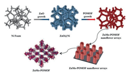
Schematic illustration for the synthesis process of ZnMo-POMOF nanoflower arrays.
In situ growth of polyoxometalate-based metal-organic framework nanoflower arrays for efficient hydrogen evolution
Lei Wang , A-Ni Wang , Zhen-Zhen Xue , Yan-Ru Wang , Song-De Han , Guo-Ming Wang

Hydrogen has been regarded as a clean, recyclable and renewable energy sources and carriers for replacing traditional fossil fuels [1-3]. Water splitting into hydrogen molecular via the hydrogen evolution reaction (HER) has attracted much attention owing to its high-purity product, low energy consumption and environmentally friendly process [4-7]. Up to now, although precious platinum (Pt) has been proved the state-of-the-art electrocatalysts for the HER, they are not widespread applied on account of their low earth abundance and high price. In the past few years, significant efforts have been made to explore the low-cost, highly active and earth-abundant non-noble metal electrocatalysts [8-11]. Fortunately, one of the most exciting families of these HER electrocatalysts, polyoxometalate-based metal−organic framework (POMOFs), with multielectron redox trans-formations activity of polyoxometalate species and well-defined chemical structures [12-14], readily accessible active sites and high porosity of metal−organic framework, have been demonstrated the promising electrocatalyst for HER [15-17].
Recently, most of the reported POMOFs crystals have been directly used for HER [18, 19], which seems straightforward and facile but is actually not the most optimized electrocatalyst. The assembled electrode by coated POMOFs crystals (especially large-sized crystals) may encounter delamination problems or be likely to fall off from the electrodes during the electrocatalytic water splitting processes [20]. In addition, the assembled electrode by coated crystals require extra binder, which inevitably buries the active sites, increases the resistance and inhibits mass transport [21]. Currently, self-supported electrocatalysts have attracted increasing interest due to the following superiority: (1) Electrocatalysts grown on conductive substrates without the assistance of the binders and conductive agent could be directly used as the self-supported working electrodes for electrochemical testing and naturally avoided the complicated post-coating process [22]; (2) Uniform distribution and high loading of electrocatalysts on the substrates provided abundant electrochemical active sites [23]; (3) The formation of heterogeneous interface between conductive substrates and electrocatalysts could dramatically accelerate the mass and charge transfer [24]. Accordingly, rational design of POMOFs crystals on the conductive substrate, will be really conducive to enhance the intrinsic electrocatalytic activities of POMOFs for efficient hydrogen evolution reaction. However, rational design of the well-defined POMOFs crystalline materials grown in-situ on the conductive substrate into self-supported electrocatalyst are rarely reported [25-28].
Herein, one unprecedented polyoxometalate-based metal–organic framework (POMOFs), [ε-PMo8VMo4VIO37(OH)3Zn4][BPB]3 (ZnMo-POMOF) was synthesized. In this compound, the POM fragments serving as nodes were directly connected with organic ligands giving rise to one-dimensional (1D) chain structure. Furthermore, ZnMo-POMOF crystals were grown in-situ on a Ni foam substrate by ZnO nanorods self-sacrifice template strategy (Scheme 1). Typically, ZnMo-POMOF nanoflower arrays on Ni foam substrate have been successfully fabricated. The obtained self-supported electrode with superstructure architecture can be directly used as the self-supported working electrodes, which provided more accessible active sites, multiple interfaces and efficient electron conducting pathway toward HER with an overpotential of 180 mV and a small Tafel slope of 66 mV/dec to achieve a current density of 10 mA/cm2 in 0.5 mol/L H2SO4.
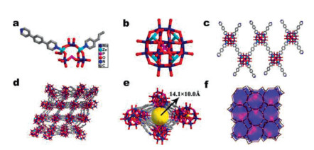
X-ray crystallography diffraction analysis demonstrates that ZnMo-POMOF crystallizes in the monoclinic space group C2/c with four formula units (Z = 4) per unit cell. The asymmetric structural unit of ZnMo-POMOF consists of a half ε-{Zn4PMo12O40} cluster as the inorganic building node, and organic ligands including one and a half BPB units as the linker (Fig. 1a) [29]. The ε-{Zn4PMo12O40} cluster is a member of compounds based on the ε-Keggin {PMo12O40} anion, which has four capping Zn(II) ions in tetrahedral symmetry (Fig. 1b). As expected, the well-known typical the ε-Keggin ion is an eight-electron-reduced polyoxometallate subunit, each ε-Keggin cluster consists of four Mo(VI) and eight Mo(V) ions, as demonstrated by the long Mo(VI)–Mo(VI) (~3.2 Å) and short Mo(V)–Mo(V) (~2.7 Å) distances. The results of bond valence sum calculations and XPS analysis obviously indicated the existence of Mo(VI) and Mo(V) oxidation states (Fig. S1 in Supporting information) [30]. The capped Zn(II) ions adopts tetrad coordination modes, which can be regarded as one types (Fig. S2 in Supporting information). All of Zn1 and Zn2 atoms are coordinated to nitrogen atoms (N1 and N3) belonging to the BPB ligands and three bridging oxygen atoms rooting in ε-{PMo12O40} anions. The average Zn–N and Zn–O distances are 2.022 Å and 1.947 Å, respectively (Fig. S3 in Supporting information). It is coincident with the other reported Zn–N and Zn–O bond lengths in the literatures [31-33]. Each Zn-ε-Keggin fragment is linked with four BPB ligands, with one of BPB ligands connects two adjacent Zn-ε-Keggin units, forming a one-dimensional (1D) chain structure (Fig. 1c). The 1D chain structure are further connected to a 3D supramolecule framework via hydrogen bonds with a rhombic channel of 14.1 × 10.0 Å (Figs. 1d and e). PLATON calculation indicated that the overall solvent-accessible volume is 3382.8 Å3, which possess 35.1% of the cell volume (9631.6 Å3) [34]. Besides, regarding the ε-{Zn4PMo12O40} cluster as a 4-connected node, BPB ligands and C–H···O hydrogen bonding interactions as linkers, ZnMo-POMOF was simplified a 3D pcu topology {66} (Fig. 1f) [35]. The detailed crystallographic information of ZnMo-POMOF is presented in Tables S1 and S2 (Supporting information).
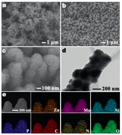
ZnMo-POMOF nanoflower arrays were synthesized through by a two-step process: (1) Firstly, highly uniform ZnO arrays are vertically supported on the conductive Ni foam substrate (termed as ZnO@Ni) via an in situ orientation growth process [36]. Scanning electron microscopy (SEM) images indicated the well-aligned ZnO arrays are made up of numerous hexagonal ZnO nanorod with the distance of 80–150 nm in diameter and 0.8–1.3 µm in length (Fig. 2a). (2) Subsequently, precursors of ZnMo-POMOF (BPB ligand, Na2MoO4·2H2O, Mo powder and H3PO3) were mixed up with aqueous solution of ZnO@Ni. ZnO arrays served the as self-sacrifice template, which provided a 3D skeleton and Zn2+ for the growth of ZnMo-POMOF. Accompanied by the continuous dissolution of ZnO and the reaction of precursor with dissolved Zn2+, ZnO nanorod arrays are almost completely etched, ZnMo-POMOF nanoflower arrays with three-dimensional hierarchical structure were successfully obtained. SEM and transmission electron microscopy (TEM) were used to characterize the morphologies of ZnMo-POMOF nanoflower arrays (Figs. S4a and b in Supporting information), which showed that dense and uniform ZnMo-POMOF nanoflower arrays vertically aligned on the conductive Ni foam substrate. Interestingly, the smooth surfaces of the ZnO nanorod arrays are fully wrapped with ZnMo-POMOF nanoflower (Figs. 2b–d). Each of the ZnMo-POMOF nanoflower pillar exists width of around 700 nm and height about 2 µm, obviously larger than that of ZnO nanorod array. At higher magnifications (Fig. S5 in Supporting information), ZnMo-POMOF nanoflower consisted of numerous small thickness of 2D nanosheets, the thickness of the nanosheets was about 20 nm and the transverse size was about 30 nm. The energy dispersive X-ray (EDX) spectrum of ZnMo-POMOF nanoflower arrays were further obtained (Fig. 2e), which demonstrated the uniform distribution of all elements including Zn, Mo, P, C, N and O. The pattern of XRD of the resultant ZnMo-POMOF nanoflower arrays matched well with that of the bulk ZnMo-POMOF crystals and simulated ZnMo-POMOF phase, indicating the formation of pure ZnMo-POMOF on the conductive Ni foam substrate (Fig. S6 in Supporting information). All the above results unambiguously confirmed that the successful preparation of ZnMo-POMOF nanoflower arrays.
To illustrate the growth mechanism, we further track the process of conversion with time-dependent reactions. Since the initial reaction conditions are acidic (pH 5), which led to the dissolution of ZnO to Zn2+, BPB ligands were able to react with the POM moiety and Zn2+ for continuous growth of ZnMo-POMOF. The high-resolution TEM (HRTEM) image clearly revealed the growth process of ZnMo-POMOF nanoflower arrays. In the initial stage (10 min), some small ZnMo-POMOF nanosheets were deposited on the surface of ZnO nanorods (Fig. S7a in Supporting information). Accompanied by the reaction time was prolonged to 1 h, more ZnMo-POMOF nanosheets are accumulated to form nanoflowers. This phenomenon reveals that the outer BPB ligands and POM moiety species can penetrate the pores of ZnMo-POMOF and react with inner Zn2+ ions the for continuous growth. Upon the reaction time was extended to 24 h, the number of ZnMo-POMOF nanosheets accumulated and tended to form a continuous nanoflowers along the ZnO nanorods (Figs. S7b and c in Supporting information). Compared with the rough and bulk ZnMo-POMOF crystals obtained by a simple hydrothermal method (Fig. S8 in Supporting information), the ZnMo-POMOF nanoflowers became ultra-thin and uniform.
The electrocatalytic HER activity of ZnMo-POMOF nanoflower arrays were firstly measured in 0.5 mol/L H2SO4 electrolyte using a typical three-electrode setup. For a comparative study, bulk ZnMo-POMOF crystals, bare Ni foam and 20 wt% commercial Pt/C were also carried out under the same condition. The polarization curve of ZnMo-POMOF nanoflower exhibited a relatively small overpotential of 180 mV at the current density of 10 mA/cm2, which was much lower than those of bulk ZnMo-POMOF crystals (270 mV) and Ni foam (355 mV) (Fig. 3a). Tafel plots obtained by the extrapolation methods were used to evaluate the electrocatalytic HER performance from a kinetic viewpoint. As shown in Fig. 3b, ZnMo-POMOF nanoflower arrays displayed the smallest Tafel slope of 66 mV/dec, which was evidently lower than bulk ZnMo-POMOF crystals (116 mV/dec) and bare Ni foam (132 mV/dec). In addition, electrochemical impedance spectroscopy (EIS) was performed to investigate electrode kinetics of the studied catalysts toward HER. Charge transfer resistance (Rct) of the ZnMo-POMOF nanoflower arrays (7.26 Ω) was much lower than those of the bulk ZnMo-POMOF crystals (29.81 Ω) and bare Ni foam (162.35 Ω) (Fig. 3c), suggesting that the more abundant active sites of the ZnMo-POMOF nanoflower arrays can promote higher charge transfer and superior HER kinetics.
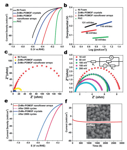
Moreover, the Rct of the ZnMo-POMOF nanoflower arrays was carried out at different overpotentials (50, 100, 150 and 200 mV) in 0.5 mol/L H2SO4 (Fig. 3d). The Rct values are 5.74 Ω, 5.67 Ω, 4.44 Ω and 3.53 Ω at η = 50, 100, 150, 200 mV, respectively (A simplified equivalent circuit shown in the insert of Fig. 3d was used to simulate the Nyquist plots). The low Rct values of ZnMo-POMOF nanoflower arrays could be attributed to the well-aligned nanoflower arrays made up of 2D nanosheets improving the fast charge transfer kinetics [37, 38]. Significantly, the ZnMo-POMOF nanoflower arrays exhibits the competitive HER activity as compared with the reported POMOF-based and Mo-based HER electrocatalyst (Table S3 in Supporting information) [39-42]. To investigate the stability of ZnMo-POMOF nanoflower arrays, the long-term cyclic voltammetry (CV) scanning before and after 2000 cycles were measured in 0.5 mol/L H2SO4 (Fig. 3e). There was only insignificant degradation in the current density after long-term cycling, which indicate that the good electrocatalytic stability of the ZnMo-POMOF nanoflower arrays. Meanwhile, i − t curves show almost negligible decrease after a long period amperometric operation (Fig. 3f). In addition, the SEM images (Fig. S9 in Supporting information) show the morphology of ZnMo-POMOF nanoflower arrays could be maintained well after HER test, further demonstrating the stability of the assynthesized ZnMo-POMOF nanoflower arrays.
Since ZnMo-POMOF nanoflower arrays possessed the highest HER electrochemical activities, it is worth exploring its intrinsic electrocatalytic mechanism. It has been proven that the HER activity is closely associated with the Gibbs free energy of hydrogen adsorption (△GH*) on the catalyst surface [43, 44]. Lan's group have selected the most representative Zn-ε-Keggin-Cl fragment of the Zn-ε-Keggin type POMOFs as calculation model to calculate the optimized value of △GH* [15]. In consideration of the identical existence of Zn-ε-Keggin fragment in our ZnMo-POMOF crystals, the most representative Zn-ε-Keggin-Cl fragment was also selected as the structural model for calculating the △GH*. According to our computations and the results of Lan's group, µ3-bridging oxygen Oa sites of the Zn-ε-Keggin-Cl are more suitable for H* adsorption with the adsorption energy of −0.07 eV, which are obviously lower than that of Ob site (0.22 eV) and Ot site (0.52 eV), respectively (Fig. S10 in Supporting information). The calculated results indicated that ZnMo-POMOF crystals indeed have good electrocatalytic activity for hydrogen evolution.
Overall, the aforementioned experimental and theoretical results have unambiguously proved that the outstanding catalytic performances of ZnMo-POMOF nanoflower arrays toward HER, which is mainly resulting from the following three aspects: (ⅰ) The Zn-ε-Keggin polymolybdate units optimized the △GH* and increased the intrinsic activity of the catalysts. (ⅱ) Nanoflower arrays structures provided sufficient accessibility redox sites and enhanced the conductivity. (ⅲ) The open self-supported electrode of ZnMo-POMOF nanoflower arrays without any binders or conductive agents expedites the release of H2 bubbles and facilitated the mass transfer, which is beneficial for enhancing the catalytic reaction kinetics and long-term electrochemical stability. Taken together, these features synergistically contribute to ZnMo-POMOF nanoflower arrays to greatly boost the electrocatalytic HER activities.
In conclusion, we have successfully fabricated 3D self-supported ZnMo-POMOF nanoflower arrays as efficient electrocatalysts for hydrogen evolution by ZnO nanorods self-sacrifice template strategy. Experimental and theoretical investigations suggest that ZnMo-POMOF nanoflower arrays exist outstanding HER catalytic activity and a long-term stability in an acidic electrolyte. Zn-ε-Keggin polymolybdate units of ZnMo-POMOF optimized the △GH*, the self-supported ZnMo-POMOF nanoflower arrays structure provided sufficient accessibility redox sites and facilitated the mass transfer, these three features synergistically contribute to the enhancement of the catalytic reaction kinetics. We are firmly believed that this newly design and synthesis of POMOF-based electrocatalysts is full of opportunities and that great progress will be made in the next few years.
The authors declare that they have no known competing financial interests or personal relationships that could have appeared to influence the work reported in this paper.
This work was supported by grants from the National Natural Science Foundation of China (Nos. 22071125 and 22071126) and Natural Science Foundation of Shandong Province (No. ZR2020QB140).
Supplementary material associated with this article can be found, in the online version, at doi:
W.M. Tong, M. Forster, F. Dionigi, et al., Nat. Energy 5 (2020) 367–377. doi: 10.1038/s41560-020-0550-8
J. Zhu, L.S. Hu, P.X. Zhao, L.Y.S. Lee, K.Y. Wong, Chem. Rev. 120 (2020) 851–918. doi: 10.1021/acs.chemrev.9b00248
Y.O. Wang, A. Vogel, M. Sachs, et al., Nat. Energy 4 (2019) 746–760. doi: 10.1038/s41560-019-0456-5
T. Hisatomi, K. Domen, Nat. Catal. 2 (2019) 387–399. doi: 10.1038/s41929-019-0242-6
C.L. Hu, L. Zhang, J.L. Gong, Energy Environ. Sci. 12 (2019) 2620–2645. doi: 10.1039/c9ee01202h
B. Deng, J. Liang, L. Yue, et al., Chin. Chem. Lett. 33 (2022) 890–892. doi: 10.1016/j.cclet.2021.10.002
X.P. Li, C. Huang, W.K. Han, T. Ouyang, Z.Q. Liu, Chin. Chem. Lett. 32 (2021) 2597–2616. doi: 10.1016/j.cclet.2021.01.047
C. Wang, L.J. Jin, H.Y. Shang, et al., Chin. Chem. Lett. 32 (2021) 2108–2116. doi: 10.1016/j.cclet.2020.11.051
J. Mohammed-Ibrahim, X. Sun, J. Energy Chem. 34 (2019) 111–160. doi: 10.1016/j.jechem.2018.09.016
Q. Shi, C. Zhu, D. Du, Y. Lin, Chem. Soc. Rev. 48 (2019) 3181–3192. doi: 10.1039/c8cs00671g
Z.P. Wu, X.F. Lu, S.Q. Zang, X.W. Lou, Adv. Funct. Mater. 30 (2020) 1910274. doi: 10.1002/adfm.201910274
Y.R. Huang, X.L. Lin, B. Chen, et al., Angew. Chem. Int. Ed. 60 (2021) 16911–16916. doi: 10.1002/anie.202104333
M. Lu, M. Zhang, J. Liu, et al., J. Am. Chem. Soc. 144 (2022) 1861–1871. doi: 10.1021/jacs.1c11987
G. Yang, X. Xie, M. Cheng, et al., Chin. Chem. Lett. 33 (2022) 1483–1487. doi: 10.1016/j.cclet.2021.08.037
J.S. Qin, D.Y. Du, W. Guan, et al., J. Am. Chem. Soc. 137 (2015) 7169–7177. doi: 10.1021/jacs.5b02688
F.Y. Yu, Z.L. Lang, Y.J. Zhou, et al., ACS. Energy Lett. 6 (2021) 4055–4062. doi: 10.1021/acsenergylett.1c01911
H.Y. Zhao, Y.Z. Li, J.W. Zhao, L. Wang, G.Y. Yang, Coord. Chem. Rev. 443 (2021) 213966. doi: 10.1016/j.ccr.2021.213966
C.Y. Sun, S.X. Liu, D.D. Liang, et al., J. Am. Chem. Soc. 131 (2009) 1883–1888. doi: 10.1021/ja807357r
B. Nohra, H. El Moll, L.M.R. Albelo, et al., J. Am. Chem. Soc. 133 (2011) 13363–13374. doi: 10.1021/ja201165c
G. Cai, W. Zhang, L. Jiao, S.H. Yu, H.L. Jiang, Chem 2 (2017) 791–802. doi: 10.1016/j.chempr.2017.04.016
H. Sun, Z. Yan, F. Liu, et al., Adv. Mater. 32 (2020) 1806326. doi: 10.1002/adma.201806326
G.F. Chen, T.Y. Ma, Z.Q. Liu, et al., Adv. Funct. Mater. 26 (2016) 3314–3323. doi: 10.1002/adfm.201505626
Z. Yan, H. Sun, X. Chen, et al., Nat. Commun. 9 (2018) 2373. doi: 10.1038/s41467-018-04788-3
H. Li, S. Chen, Y. Zhang, et al., Nat. Commun. 9 (2018) 2452. doi: 10.1038/s41467-018-04888-0
Y. Gu, A. Wu, Y. Jiao, et al., Angew. Chem. Int. Ed. 60 (2021) 6673–6681. doi: 10.1002/anie.202016102
J. Hao, J. Liu, D. Wu, et al., Appl. Catal. B 281 (2021) 119510. doi: 10.1016/j.apcatb.2020.119510
X. Ren, D. Wu, R. Ge, et al., Nano Res. 11 (2018) 2024–2033. doi: 10.1007/s12274-017-1818-6
C. Wang, L. Qi, Angew. Chem. Int. Ed. 59 (2020) 17219–17224. doi: 10.1002/anie.202005436
Z.Z. Xue, X.D. Meng, X.Y. Li, et al., Inorg. Chem. 60 (2021) 4375–4379. doi: 10.1021/acs.inorgchem.1c00280
Y. Mu, D. Wang, X.D. Meng, et al., Cryst. Growth Des. 20 (2020) 1130–1138. doi: 10.1021/acs.cgd.9b01448
X.X. Li, F.C. Shen, J. Liu, et al., Chem. Commun. 53 (2017) 10054–10057. doi: 10.1039/C7CC05552H
X.X. Li, J. Liu, L. Zhang, et al., ACS Appl. Mater. Interfaces 11 (2019) 25790–25795. doi: 10.1021/acsami.9b03861
Y.R. Wang, Q. Huang, C.T. He, et al., Nat. Commun. 9 (2018) 4466. doi: 10.1038/s41467-018-06938-z
Z. Wang, H.F. Su, Y.W. Gong, et al., Nat. Commun. 11 (2020) 308. doi: 10.1038/s41467-019-13682-5
Y. Wang, A. Wang, Z. Xue, et al., J. Mater. Chem. A 9 (2021) 22597–22602. doi: 10.1039/d1ta06360j
L. Wang, X. Li, Q. Li, et al., Small 15 (2019) 1900900. doi: 10.1002/smll.201900900
Z.P. Lin, B.B. Xiao, Z.P. Wang, et al., Adv. Funct. Mater. 31 (2021) 2102321. doi: 10.1002/adfm.202102321
B. Zhang, Y.J. Zheng, T. Ma, et al., Adv. Mater. 33 (2021) 2006042. doi: 10.1002/adma.202006042
H. Xu, H.Y. Shang, C. Wang, Y.K. Du, Coord. Chem. Rev. 418 (2020) 213374. doi: 10.1016/j.ccr.2020.213374
C. Guan, W. Xiao, H.J. Wu, et al., Nano Energy 48 (2018) 73–80. doi: 10.1016/j.nanoen.2018.03.034
X.X. Li, D. Zhao, S.T. Zheng, Coord. Chem. Rev. 397 (2019) 220–240.
Z.K. Zhu, Y.Y. Lin, H. Yu, X.X. Li, S.T. Zheng, Angew. Chem. Int. Ed. 58 (2019) 16864–16868. doi: 10.1002/anie.201910477
S. Zhao, C. Tan, C.T. He, et al., Nat Energy 5 (2020) 881–890. doi: 10.1038/s41560-020-00709-1
R. Ge, J. Huo, T. Liao, et al., Appl. Catal. B 260 (2020) 118196. doi: 10.1016/j.apcatb.2019.118196

Scheme 1 Schematic illustration for the synthesis process of ZnMo-POMOF nanoflower arrays.

Figure 1 (a) Asymmetric unit of ZnMo-POMOF. (b) The ε-{Zn4PMo12O40} cluster. (c) View of the 1D chain. (d, e) View of the 3D structure and channels. (f) pcu topology.

Figure 2 (a) SEM image of ZnO nanorod arrays on conductive nickel foam substrate. (b) SEM image of ZnMo-POMOF nanoflower arrays. (c) Enlarged view of b. (d) TEM analysis of nanoflower arrays morphology for ZnMo-POMOF. (e) Elemental mapping images of ZnMo-POMOF nanoflower arrays.

Figure 3 (a) HER polarized curves. (b) The corresponding Tafel slopes of the as-prepared electrocatalysts in 0.5 mol/L H2SO4. (c) EIS curves. (d) EIS curves at different overpotential. Inset in (d) is the corresponding equivalent circuit diagram of the as-synthesized ZnMo-POMOF nanoflower arrays composites. (e) CV curves before and after 2000 cycles. (f) Chronopotentiometric measurement of ZnMo-POMOF nanoflower arrays. Inset is the SEM image of ZnMo-POMOF nanoflower arrays before and after chronopotentiometric measurement.

 扫一扫看文章

扫一扫关注我们
 DownLoad:
 下载:
下载: