School of Chemistry and Materials Science, Jiangsu Provincial Key Laboratory of Material Cycling and Pollution Control, Jiangsu Collaborative Innovation Center of Biomedical Functional Materials, Nanjing Normal University, Nanjing 210046, China
b.
Ningbo Institute of Materials Technology & Engineering, Chinese Academy of Sciences, Ningbo 315000, China
* Corresponding author. E-mail address: yangzhen@njnu.edu.cn (Z. Yang). 1 These authors contributed equally to this work.
Received Date:
17 January 2022 Accepted Date:
01 April 2022 Revised Date:
11 February 2022 Available Online:
15 February 2023
Abstract:
Hydroxyl radicals (•OH) generated on anode play a vital role in electrochemical oxidation (EO) of organic pollutants for water treatment. Inspired by the four-electron oxygen evolution reaction (OER), we supposed an anode-selection strategy to stabilize deeply oxidized states (*O and *OOH) which are beneficial to generating •OH. To verify the hypothesis, a candidate anode component (MIL-101(Cr), a well-known metal-organic framework with active variable-valence transition metal centers) was used to coat Ti/TiO2 plate to fabricate anodes. Compared to TiO2(101) plane on undecorated anode surface, fast and complete removal of aniline and phenol, and improved energy utilization were achieved on MIL-101(Cr)-coated-Ti/TiO2 anode. Mechanism investigation, including pollutant degradation pathways, showed the predominate contribution (69.60%–75.13%) of •OH in pollutant mineralization. Density functional theory (DFT) computations indicated Cr site in MIL-101(Cr) was more conducive to stabilizing *O and *OOH, leading to thermodynamical spontaneous generation of •OH. This work opens up an exciting avenue to explore •OH production, and supplies a useful guidance to the development of anode materials for EO process.
Advanced oxidation processes (AOPs) have been widely implemented in water purification to degrade organic pollutants using the in-situ generated highly reactive oxygen species (ROS) [1-3]. Electrochemical oxidation (EO) has been highlighted due to its features of high efficiency, no additional chemical, and operation at ambient temperature and pressure [4-6]. In an EO process, recalcitrant organic pollutants are mostly degraded by hydroxyl radicals (•OH, E0 (•OH/H2O) = 1.9–2.7 V), generated at anode surface [7-10]. Promoting the generation of •OH is thus favored for the performance improvement.
One pathway for •OH generation at the surface of metal-containing anodes (e.g., mixed metal oxide (MMO)) involves following steps: (1) H2O is adsorbed onto active site and then oxidized to adsorbed hydroxyl radicals (*OH) under external bias (Eq. 1) [11, 12]:
(1)
(2) Pseudo-free •OH is then released by homolysis of M-O bond (Eq. 2) [13–15]:
(2)
In most situations, Eq. 1 takes place easily since the adsorption of H2O onto metal site of non-active metal oxide is spontaneous due to the strong M-O covalent bond [16]. However, Eq. 2 (homolysis of M−O bond) is not always facile to happen due to the significant difference of electronegativity between metal and oxygen and intense solvation effect. Instead, heterolysis is more inclined to take place [17-19].
Oxygen evolution reaction (OER), in which H2O is initially adsorbed and O2 is finally produced at the anode surface through a four-step proton-coupled electron transfer process (Eqs. 1 and 3–5) has been extensively studied [20-22].
(3)
(4)
(5)
It is well acknowledged that production of molecular oxygen in Eq. 5 is regarded as a side reaction which significantly decreases current efficiency in EO for water treatment [23]. However, inspired by the pathway of OER, we propose the other two candidates (*O and *OOH), besides *OH, could also serve as sources for •OH production: If *O could oxidize H2O to form •OH (Eq. 6) and the weak O−O bond of *OOH break into •OH (Eq. 7), the generation of •OH would be promoted.
(6)
(7)
In the proposed ways, ideal scenario according to the hypothesis needs to meet following requirements: (1) Gibbs free energy changes (ΔG) of Eqs. 4 and 5 should be as high as possible, indicating the stabilization of *O and *OOH and the inhibition of O2 generation; (2) Simultaneously, Eqs. 6 and 7 are thermodynamically spontaneous (ΔG < 0). Therefore, selecting anode materials with suitable surface structure addressing the above requirements is a key factor. However, similar strategy has not been reported before, to the best of our knowledge.
Metal-organic frameworks (MOFs), especially water-stable ones, with porous structure have drawn attention for water treatment [24-26]. Large surface area and abundant micropores have proven conducive to the preconcentration of pollutants [27, 28]. In addition, when active transition metals with variable valences are employed as center metals (such as MIL-101(Cr)), they are possible to be candidate anode component to meet the aforementioned EO requirements. However, due to the low electrical conductivity and relatively weak stability in long-term use, MOFs were usually utilized as precursors to derive carbon-based composite electrodes after thermal treatment, which would potentially damage the ordered porous structure, as well as losing active sites and producing new pollutants during MOF pyrolysis. Instead, to directly use appropriate MOFs as the main electrocatalysts on anodes, polystyrene (PS) and graphite could be used as adhesive and conductive agent, respectively, to enhance the stability and conductivity of anodes.
In this work, to verify the above hypothesis related to Eqs. 4–7 (stabilizing *O and *OOH to promote •OH generation), MIL-101(Cr) decorated Ti/TiO2 composite anode were tested for EO of model aromatic pollutants (aniline and phenol) solutions. Aromatic pollutants are notorious and hazardous due to their bio-accumulative and non-degradable natures, which are related to various health problems such as cancer, cardiovascular diseases, obesity, reproductive and neurological ailments [29, 30]. First of all, a series of MIL-101(Cr) coated Ti/TiO2 anodes were prepared and characterized; verification experiments of the obtained anodes, involving effects of various parameters (pH, current density, and electrolyte concentration), pollutant degradation kinetics, mineralization efficiency, energy consumption, quantitative contribution of various radicals, and degradation pathways, were systematically studied; addressing the possible challenge in anode stability, long-term operation performance and environmental risk were also evaluated. Then, thermodynamic properties (related to Eqs. 4-7) of surfaces of (1) anatase TiO2(101) plane exposed on the Ti/TiO2 substrate surface and (2) secondary building unit (SBU) of MIL-101(Cr) (the calculation models were shown in Fig. S1 in Supporting information) were calculated by using density functional theory (DFT) computation to get insights into the EO mechanism [31, 32].
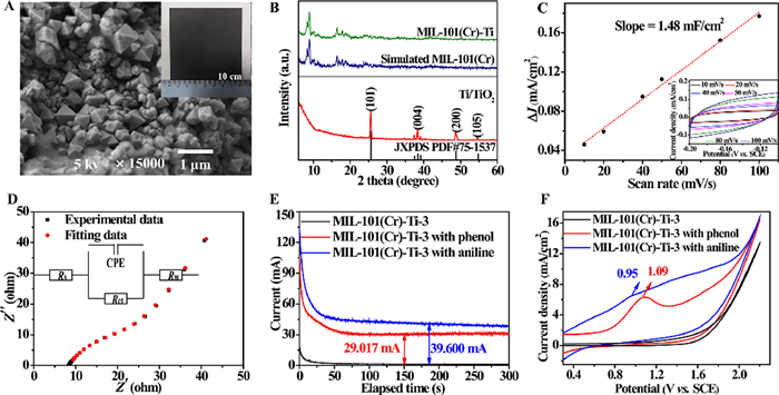
The fabricated MIL-101(Cr)-Ti-X electrodes, as well as the unmodified Ti/TiO2 for comparison, were characterized. Linear sweep voltammetry (LSV) curves and the EO performance for aniline or phenol degradation of different MIL-101(Cr)-Ti-X electrodes were conducted to optimize the ingredient (Figs. S2-S4 in Supporting information). Since a higher onset potential of oxygen evolution implies the increased difficulty of the side reaction (oxygen evolution) and a higher efficiency of pollutant oxidation [33], the optimized ratio of PS: graphite: MIL-101(Cr), according to LSV curves, is found to be 1.0: 1.0: 0.9 (MIL-101(Cr)-Ti-3, with a potential of 1.76 V vs. Saturated Calomel Electrode (SCE)). According to the degradation efficiencies and rates (Fig. S4), MIL-101(Cr)-Ti-3 is also the optimized anode, which is consistent with the conclusion obtained from LSV results. For the optimized anode, the coating thickness (12.5 µm), the octahedral crystals, and the existence of Cr(Ⅲ) were observed by scanning electron microscope (SEM, Fig. 1A and Fig. S5 in Supporting information), the similar X-ray diffraction (XRD) pattern to the simulated one of MIL-101(Cr) (Fig. 1B), and the X-ray photoelectron spectra (XPS) in Fig. S6 (Supporting information). It is thus concluded that the MOF structure is retained and exposed after the fabrication process. Besides, XRD peak of anatase TiO2 (originally on the substrate surface) is not detected for the MIL-101(Cr)-Ti-3, indicating the complete coverage of the anode surface by the MOF catalytic layer.
Figure 1
Figure 1.
(A) SEM image and actual photo (inset) of the surface of MIL-101(Cr)-Ti-3 anode. (B) XRD patterns of different anodes. (C) Average current density (ΔJ) on MIL-101(Cr)-Ti-3 anode at −0.05 V (vs. SCE) against scan rate for the calculation of double layer capacitance (Cdl) (Inset: Cyclic voltammetry (CV) curves of MIL-101(Cr)-Ti-3 anode with different scanning rates from 10 mV/s to 100 mV/s). (D) Electrochemical impedance spectroscopy of MIL-101(Cr)-Ti-3 anode (Inset: the simplified equivalent circuit). (E) Chronoamperometric curves with and without pollutants on MIL-101(Cr)-Ti-3 anode over electrolysis time. (F) CV curves of MIL-101(Cr)-Ti-3 anode without and with the existence of phenol (or aniline).
According to the cyclic voltammetry (CV) curves in a non-Faradaic potential window (inset of Fig. 1C), MIL-101(Cr)-Ti-3 always has stronger current density response (Fig. 1C) than Ti/TiO2 as shown in Fig. S7 (Supporting information). Electrochemically active surface area (ECSA) of MIL-101(Cr)-Ti-3 are more than four times that of Ti/TiO2, indicating MIL-101(Cr)-Ti-3 has more exposed active sites [34]. Then, charge transfer resistance (Rct), a key parameter to quantify the kinetic behavior of the catalyst, was obtained by fitting the Nyquist plots (Fig. 1D and Fig. S8 in Supporting information) with an equivalent circuit [35]. Compared to Ti/TiO2 (Rct: 331.40 Ω), MIL-101(Cr)-Ti-3 notably facilitates charge transfer with a far smaller Rct (13.28 Ω).
Chronoamperometric tests with the existence of pollutant were conducted to explore the electrochemical response current (Fig. 1E and Fig. S9 in Supporting information) [36]. For either of the pollutants, the current gap of MIL-101(Cr)-Ti-3 between the blank and pollutant solution is larger than that of Ti/TiO2, verifying the higher probability of electrocatalytic reaction towards organic pollutants and higher anodization efficiency of MIL-101(Cr)-Ti-3. Fig. 1F and Fig. S10 (Supporting information) represent the CV curves of the anodes in pollutant solutions. Oxidation peaks at 1.09 V and 0.95 V vs. SCE correspond to the existence of direct oxidation of phenol and aniline via direct electron transfer on anode surface, respectively. Despite this, indirect •OH-mediated oxidation will be found predominant in following mechanistic investigations.
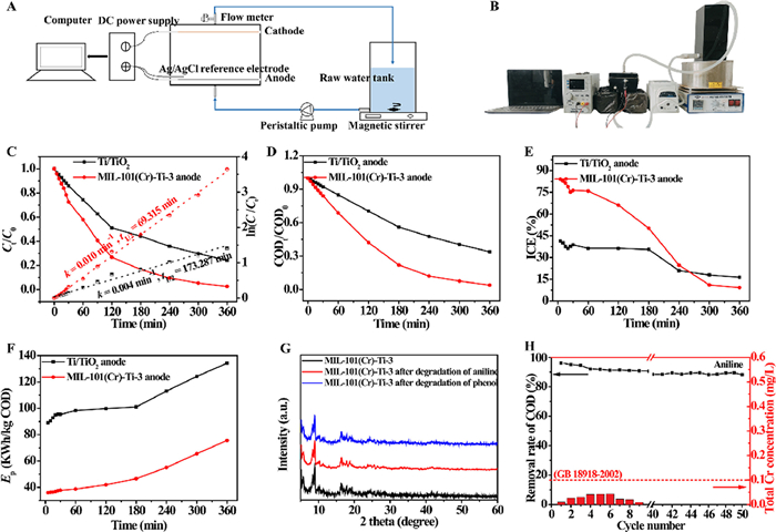
Practical EO performance of the MIL-101(Cr)-modified composite anode was evaluated in a self-made flow-through electrochemical reactor (Figs. 2A and B). Effects of key parameters, involving solution pH, applied current density, and supporting electrolyte concentration, on the removal of pollutants were studied in detail (Texts S2-S4 and Figs. S11-S15 in Supporting information). The obtained optimal parameters are solution pH of 9, current density of 20 mA/cm2, and supporting electrolyte concentration of 0.10 mol/L. Under the optimal conditions, the aniline and phenol removal efficiencies on MIL-101(Cr)-Ti-3 reach to 97.4% and 95.8%, respectively, much higher than those of Ti/TiO2 electrode (75.7% and 67.3%) after 6 h (Fig. 2C and Fig. S16A in Supporting information). The derived curves of ln(C0/Ct) versus time show good linear relationships (R2 > 0.98), illustrating the pseudo-first-order degradation kinetics. The removal half-lives (t1/2) of Ti/TiO2 anode are 2.5 times that of MIL-101(Cr)-Ti-3 for aniline, and 2.7 times for phenol. In general, mineralization efficiency of recalcitrant organic pollutants matters more [37]. Thus, COD of the treated water was further measured (Fig. 2D and Fig. S16B in Supporting information). MIL-101(Cr)-Ti-3 also has higher COD removal efficiencies for both contaminants than the unmodified Ti/TiO2, exhibiting a robust continuous oxidation ability for various intermediate products.
Figure 2
Figure 2.
(A) Schematic diagram and (B) actual photo of the electrochemical oxidation reactor. (C) Aniline removal and corresponding kinetic fitting curves on the as-prepared anodes. (D) COD removal of the aniline solution on the as-prepared anodes. (E) Instantaneous current efficiency (ICE) and (F) energy consumption (Ep) as functions of time during aniline EO process on the as-prepared anodes. (G) XRD patterns of the freshly-prepared and used MIL-101(Cr)-Ti-3 anodes. (H) COD removal and Cr leaching concentrations using MIL-101(Cr)-Ti-3 anode for aniline removal in 50 cycles.
Considering the energy and economic benefit aspect, instantaneous current efficiency (ICE) and energy consumption (Ep) were calculated as well (Figs. 2E and F, Figs. S16C and D in Supporting information). Despite the downward trend of ICE and upward trend of Ep due to the lowered concentration of pollutants with time, MIL-101(Cr)-Ti-3 always shows significantly higher ICE and lower Ep than Ti/TiO2 in the first 3 h. Besides, the average current efficiency (ACE) of the MIL-101(Cr)-Ti-3 system in the total 6 h are 39.8% and 33.0% for aniline and phenol degradation, respectively; both are much higher than those of the Ti/TiO2 system. When compared to several reported MMO anodes (Table S2 in Supporting information), MIL-101(Cr)-Ti-3 also has notable advantages. The lowered Ep results from two reasons, including the enhanced preconcentration and mass transfer of pollutant into the abundant micropores of MIL-101(Cr) (Table S3 and Figs. S17 and S18 in Supporting information), and the stabilized *O and *OOH at the MOF surface which can generate more •OH for pollutant mineralization (described below).
Environmental concerns may arise from the aspects of the stability of the MOF-modified anode and Cr leaching risk under anodic polarization condition [38]. Leaching of total Cr, Cr(Ⅲ) and Cr(Ⅵ) from the anode at different current densities (Fig. S19 in Supporting information) demonstrates that, with the increase of current density, obvious dissolution of Cr(Ⅲ) from MIL-101(Cr) starts at 25 mA/cm2 and oxidation into Cr(Ⅵ) starts at 30 mA/cm2. Thus, 20 mA/cm2, the optimized parameter as aforementioned, could be feasible. XRD patterns (Fig. 2G), FTIR spectra and SEM images (Figs. S20 and S21 in Supporting information) of used MIL-101(Cr)-Ti-3 remain nearly the same to those of the unused one, demonstrating the stability of the MOF structure. When tested in 50 cycles of running for evaluating the long-term performance (Fig. 2H and Fig. S22 in Supporting information; each cycle contained an EO operation under optimal conditions for 6 h and an anode-washing step using water), COD removal efficiencies decrease slightly and continuously during the 50 cycles of running, but remained high levels, ~89% and ~82% for aniline and phenol, respectively, at the 50th cycle. Meantime, Cr leaching concentrations reach peak values at the 6th cycle and then decline gradually to near zero at the 40th cycle. Cr leaching concentrations are always much lower than the limit value in the Chinese national discharge standard of pollutants for municipal wastewater treatment plant (GB18918-2002). XPS spectra (Fig. S6) of used anode still keep similar to those of new anode. All the results showed the stability of the anode.
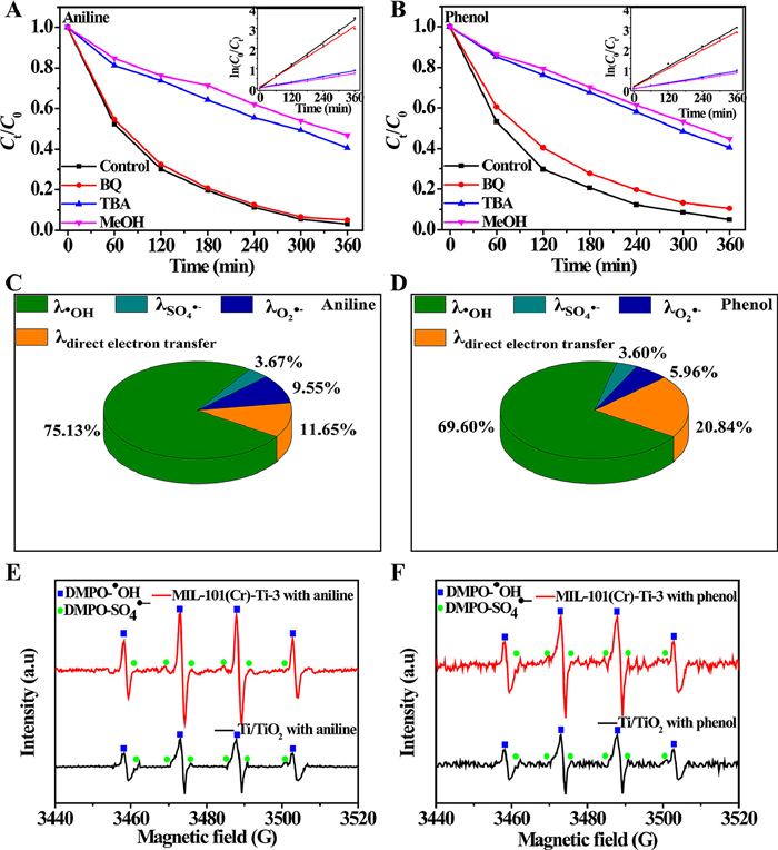
To identify the contribution of various radicals, as well as the aforementioned direct oxidation, in pollutant degradation, EO experiments were carried out with the presence of radical scavengers (Figs. 3A and B). Tert-butyl alcohol (TBA) and 1,4-benzoquinone (BQ) were used to scavenge •OH, and O2•−, respectively, whereas MeOH could scavenge both SO4•− and •OH [39-41]. Similar removal efficiencies with and without the presence of BQ suggest that the contribution of O2•− radicals is less than 10%; the large reduction of removal efficiencies, when TBA is added, indicates the dominant role of •OH in organic compound degradation; SO4•−, despite the use of Na2SO4 as electrolyte, provides only a small contribution since removal efficiencies decrease slightly when TBA is replaced by MeOH. Pseudo-first-order model fits well with all curves (insets of Figs. 3A and B), and according to the obtained rate constants, contribution of various radicals and direct oxidation in pollutant degradation were quantified (Figs. 3C and D) using Eqs. S5-S8 in Supporting information. Direct electron transfer on the anode surface, existing as aforementioned in Fig. 1F, leads to 11.65%−20.84% of the degradation. Despite this, for either aniline and phenol, •OH contributes to the largest part, 69.60%−75.13%, of pollutant degradation. Electron paramagnetic resonance (EPR) spectra (Figs. 3E and F; 5,5-dimethyl-1-pyrroline-N-oxide (DMPO) used as a spin-trap for •OH and SO4•−) confirm the dominant contribution of •OH (stronger intensities of the characteristic 1:2:2:1 peaks than those of the DMPO-SO4•− peaks) [42]. For both aniline and phenol, the intensities of DMPO-•OH in the MIL-101(Cr)-Ti-3 system are always stronger than those in the Ti/TiO2 system, further indicating more •OH produced, which enhances the EO process. Since the predominant role of •OH is identified, the degradation pathways of the pollutants for the total mineralization (COD removal), including hydroxylation, ring-opening and decarboxylation processes, can be illustrated (Fig. S23 in Supporting information) according to LC-MS results (Figs. S24-S27 in Supporting information) and previous literatures [15, 43, 44]: (1) The attack of •OH onto the reactive site of phenol yields different primary intermediates of catechol, resorcinol, hydroquinone; for aniline, the presence of hydroquinone and 4-(phenylimino)cyclohexa-2,5-dien-1-one indicates that the aniline oxidation starts by the oxidation of amine group and consecutive dimer formation. (2) The above intermediates turn into unstable benzoquinone, which are further converted into maleic acid by ring-opening reaction. (3) Maleic acid is then decomposed into carboxylic acids with shorter carbon chains, which are finally decomposed into CO2 and H2O.
Figure 3
Figure 3.
Effects of BQ, TBA and MeOH on (A) aniline and (B) phenol removal on MIL-101(Cr)-Ti-3 anode (Inset: the corresponding kinetic fitting curves). Relative contribution of •OH, SO4•−, O2•− and direct electron transfer for (C) aniline and (D) phenol removal on MIL-101(Cr)-Ti-3 anode. Electron paramagnetic resonance (EPR) signals of reactive radical after 5 min of EO processes in (E) aniline and (F) phenol solutions on MIL-101(Cr)-Ti-3 anodes.
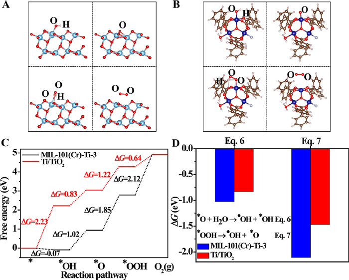
In order to further understand the related mechanism of •OH on MIL-101(Cr)-decorated Ti/TiO2 anode, DFT calculations, as implemented in the Vienna ab initio Simulation package (VASP) were performed (details see Text S1 in Supporting information) [45-49]. Optimized configurations of intermediates absorbed on the two models, with corresponding free energy profiles, in OER process are presented in Figs. 4A-C. For anatase TiO2(101) plane, the potential determining step (PDS) is the first step (Eq. 1 with a ΔG of 2.23 eV). It means that *OH is difficult to be produced on the exposed Ti(Ⅳ) site; however, once the *OH species is generated under external bias, oxygen molecule is readily produced. Differently, PDS is the last step (Eq. 5) for SBU of MIL-101(Cr), indicating that the MIL-101(Cr) surface is more prone to stabilize *O and *OOH in Eqs. 3 and 4, respectively, with a proper voltage applied. Furthermore, the negative ΔG values of Eqs. 6 and 7 on both surfaces (Fig. 4D) show that the production of •OH from *O and *OOH is spontaneous, and occurs more readily on SBU of MIL-101(Cr) with more negative ΔG. Hence, the exposed Cr sites in MIL-101(Cr) are supposed to be effective active catalytic center for EO process.
Figure 4
Figure 4.
Optimized configurations of *OH, *O, *OOH and O2(g) on (A) anatase TiO2 (101) plane and (B) secondary building unit (SBU) of MIL-101(Cr) surface. (C) Free energy profiles for the OER pathway on anatase TiO2 (101) plane and SBU of MIL-101(Cr) surface. (D) Gibbs free energy variation (ΔG) of and.
In summary, MIL-101(Cr)-Ti-3 anode was fabricated with enhanced performance for EO of aromatic compound removal. Compared to TiO2(101) plane on undecorated anode surface, MIL-101(Cr)-Ti-3 anode achieved fast and complete removal of aniline and phenol, and improved energy utilization. Mechanism investigation, involving contribution identification of different radicals and contaminant degradation pathways, showed the predominate role of •OH in pollutant mineralization. A new strategy, by stabilizing *O and *OOH yet inhibiting O2 generation in OER process was proposed and verified for improving the generation of •OH which further enhance the EO performance in aromatic pollutant removal from water. DFT computations, demonstrated the superiority as an important tool for anode material selection. The current work opens up new opportunities for further development of high-performance anodes in EO for water purification.
Declaration of competing interest
The authors report no declarations of interest.
Acknowledgments
This work was supported by the National Natrual Science of China (NSFC, Nos. 51978341, 52070100 and 52011530433), the Natural Science Foundation of Jiangsu Province of China (No. BK20190087), Jiangsu Key Laboratory of New Power Batteries, and a project funded by the Priority Academic Program Development (PAPD) of Jiangsu Higher Education Institutions. Help and suggestions from Prof. Jelena Radjenovic at Catalan Institute for Water Research (ICRA) is highly appreciated. The authors also gratefully acknowledge the support from the Scientific Computing Center of NNU.
Supplementary materials
Supplementary material associated with this article can be found, in the online version, at doi:10.1016/j.cclet.2022.04.002.
Figure 1
(A) SEM image and actual photo (inset) of the surface of MIL-101(Cr)-Ti-3 anode. (B) XRD patterns of different anodes. (C) Average current density (ΔJ) on MIL-101(Cr)-Ti-3 anode at −0.05 V (vs. SCE) against scan rate for the calculation of double layer capacitance (Cdl) (Inset: Cyclic voltammetry (CV) curves of MIL-101(Cr)-Ti-3 anode with different scanning rates from 10 mV/s to 100 mV/s). (D) Electrochemical impedance spectroscopy of MIL-101(Cr)-Ti-3 anode (Inset: the simplified equivalent circuit). (E) Chronoamperometric curves with and without pollutants on MIL-101(Cr)-Ti-3 anode over electrolysis time. (F) CV curves of MIL-101(Cr)-Ti-3 anode without and with the existence of phenol (or aniline).
Figure 2
(A) Schematic diagram and (B) actual photo of the electrochemical oxidation reactor. (C) Aniline removal and corresponding kinetic fitting curves on the as-prepared anodes. (D) COD removal of the aniline solution on the as-prepared anodes. (E) Instantaneous current efficiency (ICE) and (F) energy consumption (Ep) as functions of time during aniline EO process on the as-prepared anodes. (G) XRD patterns of the freshly-prepared and used MIL-101(Cr)-Ti-3 anodes. (H) COD removal and Cr leaching concentrations using MIL-101(Cr)-Ti-3 anode for aniline removal in 50 cycles.
Figure 3
Effects of BQ, TBA and MeOH on (A) aniline and (B) phenol removal on MIL-101(Cr)-Ti-3 anode (Inset: the corresponding kinetic fitting curves). Relative contribution of •OH, SO4•−, O2•− and direct electron transfer for (C) aniline and (D) phenol removal on MIL-101(Cr)-Ti-3 anode. Electron paramagnetic resonance (EPR) signals of reactive radical after 5 min of EO processes in (E) aniline and (F) phenol solutions on MIL-101(Cr)-Ti-3 anodes.
Figure 4
Optimized configurations of *OH, *O, *OOH and O2(g) on (A) anatase TiO2 (101) plane and (B) secondary building unit (SBU) of MIL-101(Cr) surface. (C) Free energy profiles for the OER pathway on anatase TiO2 (101) plane and SBU of MIL-101(Cr) surface. (D) Gibbs free energy variation (ΔG) of and.

 DownLoad:

 下载:
下载:


