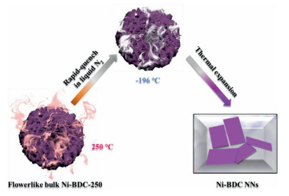
Figure 1.
Synthetic procedure for Ni-BDC NNs by a thermal expansion method.
Thermal expansion-quench of nickel metal-organic framework into nanosheets for efficient visible light CO2 reduction
Liuyong Chen , Qinglin Liu , Jun Yang , Yinle Li , Guangqin Li

Sunlight-driven catalytic reductive CO2 deoxygenation into chemicals feedstock compounds or valuable carbon-based fuels, which have been considered as a possible long-term and sustainable tactic to simultaneously ameliorate energy shortage and reduce climate-changing CO2 emissions [1-13]. However, a critical issue in this strategy is the development of efficient CO2 photoreduction system with high selectivity for practical applications, due to the sluggish kinetics of multielectron reaction process and the high dissociation energy of C = O bond [14, 15]. The light-stimulated CO2 reduction uses solar energy to fulfill this crucial mission, which usually unearths semiconductors, electron mediators, dyes, and coupling to CO2 activators [16-18]. Thus, great efforts have been devoted to unearthing light harvesters, CO2 activators, electron-transport carriers and their integration into a photocatalytic reaction system for catalytic reductive CO2 deoxygenation [19, 20].
Metal-organic frameworks (MOFs) [21-27], a typical class of microporous crystalline materials composed of tailorable bridging organic ligands and high-density metal nodes, have received great attention in many fields, including luminescence, chemical sensing, catalysis, drug delivery, and gas storage and separation [21-25]. Benefitting from abundant active sites and diverse architectures, MOFs are emerging as promising photocatalysts for reductive CO2 deoxygenation [28-30]. As a 2D material, MOF nanosheets (MOF NNs) with a thickness of several nanometers, are not only able to afford rapidly charge transfer and mass transport, but also possess plentiful and accessible active sites for improving the performance of catalysis [31-33]. Unfortunately, converting normal bulk MOF material into ultrathin nanosheets has proved challenging because intralayer coordination bonds of MOF are easily destroyed [34]. Two main strategies, bottom-up and top-down, have been applied to fabricate 2D MOF NNs. The bottom-up method mainly relies on the utilization of surfactants [35] or substrates [36], which limits their mass production and applications. Even so, MOF NNs synthesized by the traditional bottom-up chemical method are still relatively thick [33, 37]. Few-layered MOF NNs are mostly prepared via top-down approaches, including electrochemical means [31], liquid-phase exfoliation [33] and ultrasound exfoliation [34, 38]. But it is still a great challenge to build MOF nanosheets in large scale and economics. Considering energy conservation, synthesizing time and yield, an ideal strategy for fabricating few-layered MOF NNs should incorporate nontoxic components, scalability, a short reaction period and nonuse of chemical reagents.
Herein, Ni-BDC NNs (Ni2(OH)2(1, 4-BDC); 1, 4-BDC = 1, 4-benzenedicarboxylate) is synthesized via an efficient and simple thermal expansion-quench method using the flowerlike bulk Ni2(OH)2(1, 4-BDC) (Ni-BDC-250) as precursor. The obtained Ni-BDC NNs exhibits significantly improved visible light CO2 reduction performance compared to the flowerlike bulky [Ni3(OH)2(1, 4-BDC)2(H2O)4]⋅2H2O (Ni-BDC) and Ni-BDC-250 under the same mild reaction condition, which benefits from much higher surface area for CO2 adsorption with more abundant active sites exposed and the stronger electron transport ability. The synthesis route of the Ni-BDC NNs is illustrated in Fig. 1. Firstly, Ni-BDC was heated to remove coordinated water molecules to gain anhydrous Ni-BDC-250. Afterward, the Ni-BDC-250 was heated to 250 ℃ in air and immediately dipped it into the cryogenic liquid N2 (−196 ℃), followed by a drastic gasification of liquid N2, thus yielding Ni-BDC NNs. The essence of this tactics lies in incorporation with a high temperature triggered expansion of Ni-BDC-250 and a subsequent liquid N2 gasification that exfoliated the Ni-BDC-250 (a thermal expansion quench method by virtue of cryogenic liquid N2, namely, quenching the high temperature expanded state to low temperature condensed state, followed by thermal expansion driven exfoliation upon temperature increase again). This process is co-friendly because liquid N2 is a nontoxic medium which can be evaporated completely after reaction, leaving no impurities in the product. The high thermostability of Ni-BDC-250 in air was confirmed by thermogravimetric analysis (Fig. S1 in Supporting information), it is suitable to apply such high temperature treatment without destructing Ni-BDC-250 structure.
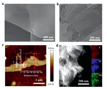
In order to demonstrate the morphology change after the liquid N2 exfoliation, the scanning electron microscopy (SEM) images of Ni-BDC, Ni-BDC-250 and Ni-BDC NNs are shown in Figs. S2 and S3 (Supporting information), Fig. 2a and Fig. S4 (Supporting information), respectively. As shown in Fig. S3, the flowerlike Ni-BDC-250 reveals obvious accumulation of the nanosheets. In Fig. 2a and Fig. S4 the resultant Ni-BDC NNs demonstrates an ultrathin nanosheet-like morphology compared to the bulky Ni-BDC-250 precursors. Meanwhile, to obtain more information about the structure and morphology of Ni-BDC NNs, transmission electron microscopy (TEM) analysis was implemented. Fig. 2b shows that the Ni-BDC NNs has an ultrathin, overlapped flat and transparent structure, which provides clear evidences that Ni-BDC NNs are exfoliated drastically into very thin layers. The thickness information of the as-made Ni-BDC NNs is further probed via atomic force microscopy (AFM) technology. As depicted in the line-scan profile of Ni-BDC NNs (20%–25% yield; Fig. 2c and Fig. S5 in Supporting information), the resultant Ni-BDC NNs possess the ultrathin structure with an average thickness of ~4.6 nm, which is about 4 atomic layers according to previously reported 1.1 nm of the single coordination structural layer of Ni-BDC [39]. Benefitting from the termination of the bonding between ligands and metal nodes, more abundant unsaturated metal sites would be exposed on the surfaces of MOF NNs compared to the bulk counterpart, thus providing an ideal model to investigate the significance of metal sites. The homogeneity of Ni-BDC NNs was further proved by scanning transmission electron microscopy (STEM) and energy-dispersive X-ray (EDX) elemental mapping, which reveals the even distribution of C, O and Ni elements on the Ni-BDC NNs throughout the whole selected area (Fig. 2d). In addition, the nitrogen adsorption-desorption tests reveal the Ni-BDC NNs with a high BET surface area of 81.6 m2/g which is about 4 times that of the Ni-BDC-250 (Fig. S6a in Supporting information). The result suggests that Ni-BDC NNs possesses more abundant active sites for surface catalysis than the Ni-BDC and Ni-BDC-250, thus accelerating mass/charge transfer to enhance photoredox catalysis. The CO2 adsorption measurement is further demonstrated that Ni-BDC NNs exhibits a maximum CO2 uptake of ca. 4.9 cm3/g at 760 mmHg and 273 K compared with Ni-BDC (1.9 cm3/g) and Ni-BDC-250 (1.7 cm3/g) (Fig. S6b in Supporting information). Compared to the Ni-BDC and Ni-BDC-250, the high BET surface area and CO2 uptakes suggest that Ni-BDC NNs possesses more abundant active sites for surface catalysis, promising for accelerating mass/charge transfer to enhance photoredox catalysis.
To further study the crystalline structure of Ni-BDC samples, XRD patterns was carried out. Fig. S7a (Supporting information) reveals that structure of Ni-BDC change completely after the high-temperature heat treatment, which has successfully translated into anhydrous Ni2(OH)2(1, 4-BDC) (Ni-BDC-250) with high thermostability [40]. In addition, we failed to detect that the Ni-BDC-250 structure was destructed after the cryogenic liquid N2 treatment. As shown in the FT-IR spectra (Fig. S7b in Supporting information), the same main characteristics can be observed for all samples. The paraaromatic CH groups and stretching vibrations of OH− give band around 1500 cm−1 and 3600 cm−1, respectively [41]. Two intense bands at 1370 cm−1 and 1580 cm−1, are assigned to characteristic absorption bands of the symmetric and asymmetric vibrations of the coordinated carboxyl group (–COO–), respectively [41]. In addition, the two bands at ca. 3055 cm−1 and 3424 cm−1 are corresponded to the stretching vibrations of water molecule [40, 42], verifying the presence of the coordinated H2O in the Ni-BDC but not for Ni-BDC-250 and Ni-BDC NNs. This result is also confirmed by thermogravimetric analysis (Figs. S1 and S8 in Supporting information).
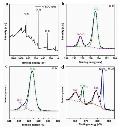
X-ray photoelectron spectroscopy (XPS) was carried out to understand the chemical valence state of the key elements. In Fig. 3a, only C, O and Ni elements were detected and the chemical valence of Ni was divalent in all specimens [42]. The bond characteristics of the Ni-BDC NNs are further demonstrated by the high-resolution C 1s, O 1s and Ni 2p spectra (Figs. 3b-d). The main peak of C 1s at 284.8 eV is attributed to C—C bands, and the subpeak at 288.4 eV is due to O—C=O bands from terephthalate. The O 1s spectrum can be deconvoluted into two O species, i.e., 531.3 eV for Ni—O bands and 533.2 eV for C—O bands [42]. In the Ni 2p spectrum (Fig. 3d), the binding energies of 855.6 eV and 873.3 eV are assigned to Ni 2p3/2 and Ni 2p1/2, respectively. And there are two satellite peaks at 861.1 eV and 879.4 eV, proving the existence of the +2 oxidation state of Ni. In addition, in the Ni 2p spectrum, the peaks of Ni 2p3/2 and Ni 2p1/2 of Ni-BDC-250 shifted to a slightly smaller binding energy compared to Ni-BDC (a shift of approximately 0.4 eV), manifesting that this structural transformation can modify local electronic structure of Ni (Fig. S9 in Supporting information). The elemental analysis by XPS (Table S1 in Supporting information), revealed that Ni content of the Ni-BDC NNs is 39.2%, which is very close to the calculated value of 37.3% based on the crystal structures.
In order to better understand the electronic band structures and the optical absorption of Ni-BDC catalyst, the diffuse reflectance spectra (DRS) were measured. As shown in Fig. S10a (Supporting information), it can be clearly observed that the optical absorption edge of Ni-BDC-250 obviously red-shifts compared with Ni-BDC, indicating that the structural transformation can modify their optical absorption tails. Furthermore, compared to the Ni-BDC-250, the intrinsic absorption edge of Ni-BDC NNs slightly blue-shift. Fig. S10b (Supporting information) shows that the bandgaps energy of Ni-BDC NNs was calculated to be 2.70 eV from the plot of the (ahv)1/2 versus photon energy. Meanwhile, the valence band (VB) energy of catalysts was obtained through the VB XPS (Fig. S11 in Supporting information), and the VB energy of Ni-BDC, Ni-BDC-250 and Ni-BDC NNs is 1.65, 1.57 and 1.98 eV, respectively. Thus, the conduction band (CB) energy of Ni-BDC, Ni-BDC-250 and Ni-BDC NNs was estimated to be −1.16, −1.05 and −0.72 eV, respectively, revealing that the Ni-MOF is a suitable catalyst for photocatalytic CO2-to-CO conversion [4]. In addition, according to the previously reported literature, the lowest unoccupied molecular orbital (LUMO) and the highest occupied molecular orbital (HOMO) energy levels of photosensitizer [Ru(bpy)3]Cl2 were −1.25 and 1.24 eV (vs. NHE) [43]. The CB energy of Ni-BDC, Ni-BDC-250 and Ni-BDC NNs is lower than that of photosensitizer [Ru(bpy)3]Cl2 LUMO energy levels and therefore the electrons on photosensitizer [Ru(bpy)3]Cl2 preferentially transfer to the Ni-BDC. To understand the separation-recombination rate of photoexcited charge carriers, the room temperature photoluminescent (PL) quenching characterization was performed on the reaction system containing Ni-BDC materials and the ruthenium photosensitizer (Ru) in H2O/acetonitrile mixture solutions (Fig. S12 in Supporting information). Obviously, the PL intensity of Ni-BDC NNs obviously decreased compared with Ni-BDC and Ni-BDC-250. The PL quenching in principle, indicates a suppressed recombination rate of the light-stimulated charge carriers [44-46].
Photocatalytic CO2 reduction reactions were conducted in H2O/acetonitrile mixture with triethanolamine (TEOA) and [Ru(bpy)3]Cl2·6H2O (abbreviated as Ru, bpy = 2, 2′-bipyridine) as the electron donor and photosensitizer, respectively, under visible-light irradiation and mild reaction conditions (λ ≥ 400 nm, 30 ℃, 1 atm CO2) [20, 47, 48]. The performance of the deoxygenative CO2 photoreduction reactions with different samples as the catalysts was shown in Fig. 4a, Ni-BDC and Ni-BDC-250 enable catalytic reductive CO2 deoxygenation under visible-light irradiation with CO-evolving rates of 4.2 and 2.3 µmol/h, respectively. However, the MOF nanosheets catalysts manifest enhanced CO2-to-CO conversion activities. Obviously, Ni-BDC NNs sample has exhibited the highest CO evolution rate of 7.0 µmol/h with a H2 generation rate of 0.56 µmol/h, acquiring a high CO selectivity of 92.6%. Moreover, photocatalytic CO2 reduction performance of Ni-BDC NNs is almost 3 times higher than Ni-BDC-250 sample. This CO2-to-CO conversion rate is comparable to those of many other CO2 photoreduction systems under comparable conditions (Table S2 in Supporting information). These results underline the outstanding CO2 reduction performance of Ni-BDC NNs, which should be related to the ultrathin two-dimension (2D) nanosheets structures for promoting the separation and transfer of light-stimulated charge carriers. In addition, we failed to detect the liquid products (e.g., CH3CH2OH, CH3OH and HCOOH) in the photocatalytic system (Fig. S13 in Supporting information), consistent with results of previously reported works [20, 39, 47, 48].
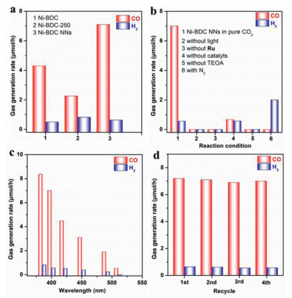
Furthermore, no detectable gas products are generated in the dark reaction system, indicating the nature of the CO2 photoreduction reaction (Fig. 4b, column 2). Meanwhile, the photosensitizer of [Ru(bpy)3]Cl2·6H2O is indispensable to realize high-efficiency performance of the CO2-to-CO conversion (Fig. 4b, column 3). Besides, the low CO evolution rate (0.67 µmol/h) and low CO selectivity (53.6%) are obtained without added Ni-BDC NNs catalyst into the catalytic system (Fig. 4b, column 4). These results demonstrate that the CO2 reduction reaction is driven by the light-stimulation of photosensitizer [Ru(bpy)3]Cl2·6H2O [39, 47, 49, 50]. No obvious photocatalytic CO2 reduction reaction is observed without TEOA, indicating that the sacrificial agent TEOA is of great significance (Fig. 4b, column 5) [48, 51-53]. In addition, when the CO2 gas is replaced by N2 in the otherwise same conditions, only a small amount of H2 are generated, and no CO product is detected in the photocatalytic reaction system (Fig. 4b, column 6), indicating that the product CO originates from photocatalytic splitting of CO2 molecules [39, 47, 48]. The wavelength-dependent experiments imply that the CO2 reduction reaction is induced by the light-stimulation (Fig. 4c). To evaluate its stability, Ni-BDC NNs is repeatedly employed to operate photocatalytic CO2-to-CO conversion reactions for four cycles. As shown in Fig. 4d and Table S3 (Supporting information), no noticeable deactivation is observed during the tests, illuminating the high stability of Ni-BDC NNs. After the photocatalytic test, XRD tests of used Ni-BDC NNs also support the stability of the material (Fig. S14 in Supporting information).
In order to study the widespread applicability of the thermal expansion method, another kind of isostructural Ni-MOF (NDC) NNs (NDC = 2, 6-naphthalenedicarboxylic acid) is synthesized via gas exfoliation method using the flowerlike bulk MOF as precursor, and was applied to catalytic CO2 reduction under visible light illumination (Fig. S15 in Supporting information) [36]. The SEM images of Ni-MOF (NDC) NNs show clearly a much smaller size and a flake-like morphology in micron-scale (Fig. S15b). As shown in Fig. S15d, Ni-MOF (NDC) NNs exhibit significantly improved CO2 photoreduction performance (8.0 µmol/h) compared to their flowerlike bulk counterpart (4.5 µmol/h).
On the basis of the experimental results, a probable mechanism for photocatalytic CO2 reduction over Ni-BDC NNs has been proposed in Fig. S16 (Supporting information). In this process, the photosensitizer [Ru(bpy)3]2+ is photo-excited to generate [Ru(bpy)3]2+* state which is then quickly reduced by the sacrificial TEOA as the electron donor, forming the reduced [Ru(bpy)3]+ species. Afterward, the [Ru(bpy)3]+ could transfer electrons to the few-layered Ni-BDC NNs catalyst, which offers rich coordinatively unsaturated Ni sites for the CO2 adsorption and concentration. Meanwhile, the adsorption of CO2 molecules on the Ni-BDC NNs surface is the committed step during the photocatalytic reaction process [39]. Benefiting from the strong CO2 molecules adsorption on the Ni-BDC NNs surface, Ni-BDC NNs is able to capture CO2 to form the CO2 adducts such as Ni-CO2 [39]. According to previous literature [54-58], the consumption of the CO2 adducts to finally form CO, which is the rate-limiting step of the catalytic reaction. Thus, Ni-BDC NNs displays remarkable activity for deoxygenative reduction of CO2.
In summary, an efficient and simple thermal expansion-quench triggered gas exfoliation method to synthesize Ni-BDC NNs has been successfully developed. The as-synthesized Ni-BDC NNs demonstrates a high specific surface area for CO2 adsorption, efficient charge separation and transfer, as well as abundant catalytically active sites for photochemical reactions, promoting the significant enhancement in CO2 photoreduction compared to those of bulk MOF. Importantly, this method has some advantages, including low energy consuming, short reaction period, high yield and easy to be scaled up. Here it has been exploited to fabricate other 2D MOF, such as Ni-MOF (NDC), also manifesting significantly improved CO2 photoreduction performance compared to their bulk. As a new strategy, the present work is of profound significance in exploiting possibilities for extensive research of the chemical and physical properties of 2D layered materials, and extending considerable potential for many applications, such as photocatalysts, photoinduced sensors and some energy storage devices.
The authors declare no conflict of interest.
This work was financially supported by the Overseas High-level Talents Plan of China and Guangdong Province, the Fundamental Research Funds for the Central Universities, the 100 Talents Plan Foundation of Sun Yat-sen University, the Program for Guangdong Introducing Innovative and Entrepreneurial Teams (No. 2017ZT07C069), National Key R&D Program of China (No. 2018YFA0108300), Local Innovative and Research Teams Project of Guangdong Peal River Talents Program (No. 2017BT01C161) and the NSFC Projects (Nos. 22075321, 21821003, 21890380 and 21905315).
Supplementary material associated with this article can be found, in the online version, at doi:
A. Listorti, J. Durrant, J. Barber, Nat. Mater. 8 (2009) 929–930. doi: 10.1038/nmat2578
T. Sakakura, J.C. Choi, H. Yasuda, Chem. Rev. 107 (2007) 2365–2387. doi: 10.1021/cr068357u
S.J. Davis, K. Caldeira, H.D. Matthews, Science 329 (2010) 1330–1333. doi: 10.1126/science.1188566
X. Li, J. Yu, M. Jaroniec, X. Chen, Chem. Rev. 119 (2019) 3962–4179. doi: 10.1021/acs.chemrev.8b00400
Q. Cheng, G.K. Zhang, Tungsten 2 (2020) 240–250. doi: 10.1007/s42864-020-00055-5
H. Gong, L. Wang, K. Zhou, et al., Adv. Powder Mater. 1 (2022) 100025. doi: 10.1016/j.apmate.2021.11.011
P. Jing, B. Wu, Z. Han, et al., Chin. Chem. Lett. 32 (2021) 3505–3508. doi: 10.1016/j.cclet.2021.04.007
H. Deng, X. Fei, Y. Yang, et al., Chem. Eng. J. 409 (2021) 127377. doi: 10.1016/j.cej.2020.127377
A. Meng, B. Cheng, H. Tan, et al., Appl. Catal. B: Environ. 289 (2021) 120039. doi: 10.1016/j.apcatb.2021.120039
Z. Wang, B. Cheng, L. Zhang, et al., Solar RRL 6 (2022) 2100587. doi: 10.1002/solr.202100587
M. Sayed, B. Zhu, P. Kuang, et al., Adv. Sustainable Syst. 6 (2022) 2100264. doi: 10.1002/adsu.202100264
B. Xia, Y. Yang, Y. Zhang, et al., Chem. Eng. J. 431 (2022) 133944. doi: 10.1016/j.cej.2021.133944
L. Wang, B. Cheng, L. Zhang, et al., Small 17 (2021) 2103447. doi: 10.1002/smll.202103447
M. Ou, W. Tu, S. Yin, et al., Angew. Chem. Int. Ed. 130 (2018) 13758–13762. doi: 10.1002/ange.201808930
J. Ran, M. Jaroniec, S.Z. Qiao, Adv. Mater. 30 (2018) 1704649. doi: 10.1002/adma.201704649
J. Ettedgui, Y. Diskin-Posner, L. Weiner, et al., J. Am. Chem. Soc. 133 (2011) 188–190. doi: 10.1021/ja1078199
K. Maeda, K. Sekizawa, O. Ishitani, Chem. Commun. 49 (2013) 10127–10129. doi: 10.1039/c3cc45532g
Y. Matsumoto, M. Obata, J. Hombo, J. Phys. Chem. 98 (1994) 2950–2951. doi: 10.1021/j100062a035
A.J. Morris, G.J. Meyer, E. Fujita, Acc. Chem. Res. 42 (2009) 1983–1994. doi: 10.1021/ar9001679
S. Wang, W. Yao, J. Lin, et al., Angew. Chem. Int. Ed. 53 (2014) 1034–1038. doi: 10.1002/anie.201309426
H. Furukawa, K.E. Cordova, M. O'Keeffe, et al., Science 341 (2013) 1230444. doi: 10.1126/science.1230444
Y. He, W. Zhou, G. Qian, et al., Chem. Soc. Rev. 43 (2014) 5657–5678. doi: 10.1039/C4CS00032C
Y. Jia, F. Zhang, Q. Liu, et al., Chin. Chem. Lett. 33 (2022) 1070–1073. doi: 10.1016/j.cclet.2021.05.052
F.L. Li, Q. Shao, X. Huang, et al., Angew. Chem. Int. Ed. 57 (2018) 1888–1892. doi: 10.1002/anie.201711376
Q. Xu, J. Zhang, D. Wang, et al., Chin. Chem. Lett. 32 (2021) 3771–3781. doi: 10.1016/j.cclet.2021.05.032
S. Mukhopadhyay, O. Basu, R. Nasani, et al., Chem. Commun. 56 (2020) 11735–11748. doi: 10.1039/D0CC03659E
Q. Liu, Q. Liu, Y. Chen, et al., Chin. Chem. Lett. 33 (2022) 374–377. doi: 10.1016/j.cclet.2021.06.047
A. Dhakshinamoorthy, A.M. Asiri, H. García, Angew. Chem. Int. Ed. 55 (2016) 5414–5445. doi: 10.1002/anie.201505581
R. Li, W. Zhang, K. Zhou, Adv. Mater. 30 (2018) 1705512. doi: 10.1002/adma.201705512
K. Niu, Y. Xu, H. Wang, et al., Sci. Adv. 3 (2017) e1700921. doi: 10.1126/sciadv.1700921
J. Huang, Y. Li, R.K. Huang, et al., Angew. Chem. Int. Ed. 130 (2018) 4722–4726. doi: 10.1002/ange.201801029
S. Zhao, Y. Wang, J. Dong, et al., Nat. Energy 1 (2016) 16184. doi: 10.1038/nenergy.2016.184
A. Dhakshinamoorthy, A.M. Asiri, H. Garcia, Adv. Mater. 31 (2019) 1900617. doi: 10.1002/adma.201900617
Y. Peng, Y. Li, Y. Ban, et al., Science 346 (2014) 1356–1359. doi: 10.1126/science.1254227
M. Zhao, Y. Wang, Q. Ma, et al., Adv. Mater. 27 (2015) 7372–7378. doi: 10.1002/adma.201503648
J. Duan, S. Chen, C. Zhao, Nat. Commun. 8 (2017) 15341. doi: 10.1038/ncomms15341
T. Rodenas, I. Luz, G. Prieto, et al., Nat. Mater. 14 (2014) 48.
K. Rui, G. Zhao, Y. Chen, et al., Adv. Funct. Mater. 28 (2018) 1801554. doi: 10.1002/adfm.201801554
B. Han, X. Ou, Z. Deng, et al., Angew. Chem. Int. Ed. 57 (2018) 16811–16815. doi: 10.1002/anie.201811545
A. Mesbah, P. Rabu, R. Sibille, et al., Inorg. Chem. 53 (2014) 872–881. doi: 10.1021/ic402106v
A. Carton, A. Mesbah, T. Mazet, F. Porcher, M. François, Solid State Sci. 9 (2007) 465–471. doi: 10.1016/j.solidstatesciences.2007.04.003
F.L. Li, P. Wang, X. Huang, et al., Angew. Chem. Int. Ed. 131 (2019) 7125–7130. doi: 10.1002/ange.201902588
K. Zhao, S. Zhao, C. Gao, et al., Small 14 (2018) 1800762. doi: 10.1002/smll.201800762
W.J. Ong, L.L. Tan, Y.H. Ng, et al., Chem. Rev. 116 (2016) 7159–7329. doi: 10.1021/acs.chemrev.6b00075
H. Yan, Y. Chen, S. Xu, Int. J. Hydrogen Energy 37 (2012) 125–133. doi: 10.1016/j.ijhydene.2011.09.072
G. Zhang, M. Zhang, X. Ye, et al., Adv. Mater. 26 (2014) 805–809. doi: 10.1002/adma.201303611
J. Qin, S. Wang, X. Wang, Appl. Catal. B: Environ. 209 (2017) 476–482. doi: 10.1016/j.apcatb.2017.03.018
Y. Ma, J. Du, Y. Fang, et al., ChemSusChem 14 (2021) 946–951. doi: 10.1002/cssc.202002656
Z. Pan, M. Liu, P. Niu, et al., Acta Phys. Chim. Sin. 36 (2020) 1906014. doi: 10.3866/PKU.WHXB201906014
H.X. Zhang, Q.L. Hong, J. Li, et al., Angew. Chem. Int. Ed. 131 (2019) 11878–11882. doi: 10.1002/ange.201905869
S. Wang, B.Y. Guan, X.W.D. Lou, J. Am. Chem. Soc. 140 (2018) 5037–5040. doi: 10.1021/jacs.8b02200
S. Wang, B.Y. Guan, Y. Lu, et al., J. Am. Chem. Soc. 139 (2017) 17305–17308. doi: 10.1021/jacs.7b10733
S. Wang, Y. Hou, X. Wang, ACS Appl. Mater. Interfaces 7 (2015) 4327–4335. doi: 10.1021/am508766s
M. Abdellah, A.M. El-Zohry, L.J. Antila, et al., J. Am. Chem. Soc. 139 (2017) 1226–1232. doi: 10.1021/jacs.6b11308
K.M. Choi, D. Kim, B. Rungtaweevoranit, et al., J. Am. Chem. Soc. 139 (2017) 356–362. doi: 10.1021/jacs.6b11027
Y. Hayashi, S. Kita, B.S. Brunschwig, et al., J. Am. Chem. Soc. 125 (2003) 11976–11987. doi: 10.1021/ja035960a
J.M. Smieja, C.P. Kubiak, Inorg. Chem. 49 (2010) 9283–9289. doi: 10.1021/ic1008363
J.K. Nganga, C.R. Samanamu, J.M. Tanski, et al., Inorg. Chem. 56 (2017) 3214–3226. doi: 10.1021/acs.inorgchem.6b02384

Figure 2 Surface morphology of Ni-BDC NNs. (a) SEM image. (b) TEM image. (c) AFM image and corresponding topographies. (d) STEM image and EDX elemental mapping images of C, O and Ni.

Figure 4 (a) CO2 photoreduction performance over different samples. (b) CO2 photoreduction activities of Ni-BDC NNs under various reaction conditions. (c) Wavelength dependence of incident light on the generation of CO/H2 by Ni-BDC NNs. (d) Stability test of photocatalytic CO2 reduction by Ni-BDC NNs.

 扫一扫看文章

扫一扫关注我们
 DownLoad:

 下载:
下载:
