Figure 1.
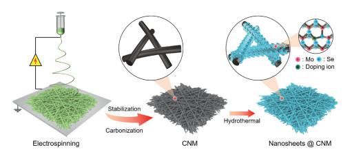
Schematic representation of the synthesis process of Zr-MoSe2 nanosheets@CNM through electrospinning of a PAN NM, conversion to a CNM, and hydrothermal synthesis of MoSe2 nanosheets in the presence of Zr4+ doping ions.
Vacancy-enhanced Mo-N2 interaction in MoSe2 nanosheets enables efficient electrocatalytic NH3 synthesis
Shuhong Wu , Meng Zhang , Shengmei Huang , Lihai Cai , Dannong He , Yitao Liu

As the main end product and important intermediate, NH3 has been widely used in the preparation of rubbers, plastics, dyes, fertilizers and medicines, which is essential to human life and economic development [1]. Furthermore, benefiting from the high weight hydrogen content (17.8 wt%) and large volumetric hydrogen energy density (12.7 MJ/L, liquid NH3), as well as the advantages of easy handling, storage and transportation of liquefaction, NH3 is also considered as a potential fuel and ideal green energy carrier in recent years [2]. Currently, industrial NH3 synthesis still relies on the traditional Haber-Bosch process with the thermocatalytic conversion of N2 and H2 in the presence of Fe-based catalysts under harsh conditions (400–600 ℃ and 20–40 MPa) due to the chemical inertness of N≡N (bond energy: 941 kJ/mol) [3]. As an energy-intensive technology for NH3 synthesis, the Haber-Bosch process accounts for more than 1% of global energy consumption each year [4]. Meanwhile, H2 used in the Haber-Bosch process is mostly produced through the decomposition of fossil fuels, causing 3%–5% of the world's natural gas consumption and leading to 1.87 tons CO2 byproduct for each ton of NH3, which will further aggravate the global greenhouse effect [5]. In result, it is imperative to develop a clean, efficient and sustainable technology alternative to the Haber-Bosch process.
Among other approaches (e.g., biocatalysis, photocatalysis, etc.) for the synthesis of NH3 by N2 reduction reaction (NRR) under ambient conditions, electrocatalytic NRR (N2 + 6H+/e– → 2NH3) has attracted increasing attention because of the following merits: (1) about 20% higher energy efficiency than the Haber-Bosch process according to the thermodynamic prediction, (2) application of renewable energy resources (solar, wind, and hydro) as the driving force for electrocatalytic NRR, (3) elimination of fossil fuels as the H2 sources via an oxidation reaction at the anode for H+, and (4) modularity, scalability and on-site, on-demand NH3 generation of the electrochemical systems [6-8]. Benefiting from the merits mentioned above, electrocatalytic NRR has great potential to replace the Haber-Bosch process. However, the industrial application of electrocatalytic NRR is still plagued by some problems such as sluggish kinetics for N2 adsorption and N≡N bond rupture which result in large overpotentials and low reaction rates, and the competition from H2 evolution reaction (HER) which leads to a low Faraday efficiency (FE) [9]. Under these circumstances, the focus of current research is to design and develop advanced catalysts to improve the activity and selectivity of electrocatalytic NRR [10].
Over the past decades, 2D transition metal dichalcogenides (TMDs) have been extensively studied in catalysis, energy storage, and optoelectronics due to their large surface area, economic feasibility, simple preparation and chemical stability [11, 12]. Among them, 2D Mo-based TMDs such as MoS2 have attracted particular attention as NRR catalysts since Mo provides the pivotal active center for N2 fixation in natural nitrogenase due to unique Mo-N2 interaction [13, 14]. Compared to MoS2, MoSe2 may have better electrochemical properties due to lower bandgap and higher conductivity [15]. As such, we explored the NRR performance of MoSe2 in our previous work; however, it was found to be unsatisfactory because the active center Mo was only exposed at the semi-open edge, and the electronegative Se-mantled surface area remained inaccessible to N2 [16]. Hence, basal plane activation through vacancy engineering has become an important strategy to improve the NRR performance by regulating the charge transport and surface adsorption capacity [17]. For example, Liu et al. synthesized vacancy-rich ReSe2 through high-temperature annealing in an inert atmosphere, and found that the introduction of Se vacancies could modulate the electronic structures of ReSe2 and enhanced its NRR performance [18]. However, this process was sophisticated, and the vacancy concentration was still limited.
Herein, we propose a simple and effective strategy to create high-concentration Se vacancies in 2D MoSe2 through heteroatom doping induced lattice strain. At first, MoSe2 nanosheets (with and without heteroatom) are facilely synthesized on a conductive matrix, i.e., a carbon nanofibrous membrane (CNM) by a one-step hydrothermal method. Considering Zr4+ has the same (and unchangeable) valence state as Mo4+, and its ionic radius (0.72 Å) is somewhat smaller than that of Mo4+ (0.79 Å), we expect it can enter the hexagonal lattice of MoSe2 and generate lattice strain substantially [19, 20]. In result, abundant Se vacancies are created, as characterized by X-Ray diffraction (XRD), electron paramagnetic resonance (EPR), and X-ray photoelectron spectroscopy (XPS). The vacancy-rich MoSe2 exhibits enhanced Mo-N2 interaction than neat MoSe2 nanosheets, delivering an NH3 yield of 3.04 × 10⁻¹⁰ mol s–1 cm–2 and an FE of 21.61% at –0.45 V vs. RHE in 0.1 mol/L Na2SO4. This strategy may pave an avenue to a new type of high-performance catalysts toward NRR.
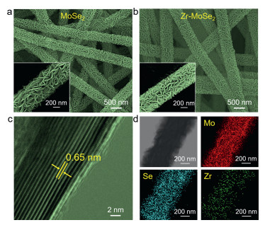
The schematic representation of the synthesis process of MoSe2 and Zr-MoSe2 nanosheets@CNM is shown in Fig. 1. Firstly, a homogeneous solution with a polyacrylonitrile (PAN) content of 13 wt% was sucked into a syringe and fabricated into a PAN nanofibrous membrane (PAN NM) through an electrospinning progress. Then, the PAN NM was stabilized in air, followed by carbonization in N2 to obtain a CNM. Finally, MoSe2 or Zr-MoSe2 nanosheets were grown on the surface of individual carbon nanofibers by a hydrothermal process (in the absence or presence of Zr4+). As shown in Fig. S1 (Supporting information), the PAN nanofibers have a smooth surface with an average diameter of around 306 nm, and are connected with each other to form a 3D porous network. After stabilization and carbonization, the average diameter of the resultant carbon nanofibers decreases to 235 nm because of the entropic shrinkage and chemical shrinkage [21]. As can be seen from the field-emission scanning electron microscopy (FESEM) images in Figs. 2a and b, both nanofibers have a core-shell structure with the carbon nanofiber skeleton uniformly decorated with nanosheets after the hydrothermal process. From the enlarged view of individual nanofibers in the insets of Figs. 2a and b, the nanosheets grow perpendicularly and form channels with open spaces on the surface of individual carbon nanofibers, which is helpful to promote the electrochemical reaction by storing the electrolyte and shortening the diffusion path of ions [22]. Taking Zr-MoSe2 nanosheets@CNM as the example, the average thickness of the shell is around 125.5 nm from the distribution of fiber diameters in Fig. S1. The high-resolution transmission electron microscopy (HRTEM) image in Fig. 2c shows that the nanosheets have an interlayer distance of 0.65 nm corresponding to the (002) plane of 2H-MoSe2 [23]. The electron dispersion spectroscopy (EDS) images of Zr-MoSe2 nanosheets@CNM in Fig. 2d reveals the homogeneous distribution of Mo, Se and Zr elements, further proving the successful synthesis of Zr-MoSe2 nanosheets on the carbon nanofiber.
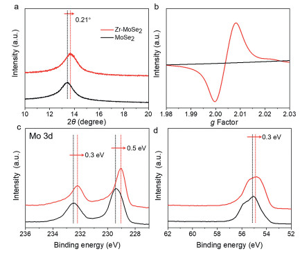
In order to determine the presence of Se vacancies in Zr-MoSe2 nanosheets@CNM, XRD, EPR and XPS measurements were performed. As shown in Fig. S2 (Supporting information), all the diffraction peaks correspond to 2H-MoSe2 (JCPDF card No. 29–0941) and no secondary phases can be detected in Zr-MoSe2 nanosheets@CNM, implying new compounds were not formed. From the enlarged view of XRD patterns at 10°–20° in Fig. 3a, slight deviation of the (002) diffraction peak can be observed in Zr-MoSe2 nanosheets@CNM due to lattice distortion. Note that Zr4+ with a smaller radius brings about a shrinkage of the MoSe2 lattice, leading to the higher shift of 2θ degree [24]. An obvious shift of 0.21° caused by the same valance state and suitable size between Zr4+ and Mo4+ is favorable for the replacement of Mo4+ by Zr4+ in the similar crystal structure and the production of abundant Se vacancies [25, 26]. Compared to MoSe2 nanosheets@CNM, a stronger EPR signal (g = 2.003) caused by the trapping of electrons in the Se vacancies of Zr-MoSe2 nanosheets@CNM can be observed in Fig. 3b, further verifying the existence of a high concentration of Se vacancies [27]. Meanwhile, when Zr4+ is incorporated in the MoSe2 nanosheets, the XPS spectra of Mo 3d3/2 and Mo 3d5/2 (Fig. 3c) as well as Se 3d (Fig. 3d) shift to lower binding energies and provide another proof of the presence of Se vacancies and Mo3+ due to the decreased electron density around Mo (Fig. S3 in Supporting information) [28, 29]. Furthermore, from the XPS spectrum of Zr 3d in Fig. S4 (Supporting information), we can conclude that Zr4+ is indeed incorporated into the lattice of the MoSe2 nanosheets [30]. The presence of Se vacancies can be directly observed under high-angle annular dark-field scanning transmission electron microscopy (HAADF-STEM), where more dark dots (missing anions) occur in the Zr-MoSe2 nanosheets@CNM (Fig. S5 in Supporting information).
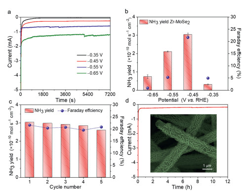
As shown in Fig. S6 (Supporting information), the Zr-MoSe2 nanosheets@CNM after the hydrothermal process can still be bent attributed to its excellent mechanical properties, which can serve as a self-supporting catalyst. The NRR performance was tested in a three-electrode system in an H-type electrolysis cell with a Nafion 212 membrane as the separator. According to the linear sweep voltammetry (LSV) curves in Fig. S7 (Supporting information), the current density in N2-saturated 0.1 mol/L Na2SO4 electrolyte is larger than that in Ar-saturated electrolyte between –0.8 V vs. RHE and –0.2 V vs. RHE, implying the effective N2 reduction of Zr-MoSe2 nanosheets@CNM [31]. The chronoamperometric curves at different potentials are shown in Fig. 4a, and no obvious fluctuation in the current can be observed, indicating good stability during the electrocatalytic process [32, 33]. The indophenol blue method was adopted to detect the concentration of NH3 at different potentials. According to the standard curves and UV–vis absorption spectra of electrolyte stained with indophenol blue indicator after 2 h reaction in Fig. S8 (Supporting information), the NH3 yield and FE can be calculated. As plotted in Fig. 4b, the highest NH3 yield (3.04 × 10⁻¹⁰ mol s–1 cm–2) and FE (21.61%) occur at –0.45 V vs. RHE for Zr-MoSe2 nanosheets@CNM. In contrast, the highest NH3 yield and FE of MoSe2 nanosheets@CNM occur at –0.55 V vs. RHE, being 1.12 × 10⁻¹⁰ mol s–1 cm–2 and 5.96%, respectively. Moreover, the NRR performance of Zr-MoSe2 nanosheets@CNM is among the best when compared to MoSe2 or MoS2-based catalysts reported elsewhere [13, 16, 34-42], due to the abundant Se vacancies generated by Zr4+ doping (Table S1 in Supporting information). Considering the stability of catalysts is a critical parameter in practical applications, cyclic and long-time electrolysis tests for Zr-MoSe2 nanosheets@CNM at –0.45 V vs. RHE were assessed. As observed in Fig. 4c, the NH3 yield and FE do not significantly change during 5 consecutive cyclic tests, showing the excellent recyclability for N2 reduction. Besides, no obvious fluctuation of current density (Fig. 4d) and well-preserved morphology of nanosheets (inset of Fig. 4d) after 12 h electrolysis suggest that Zr-MoSe2 nanosheets@CNM has a good electrochemical durability. The possible byproduct N2H4 was not detected after 12 h electrolysis by the Watt and Chrisp method (Fig. S9 in Supporting information). Note that these values are significantly lower than those of Zr-MoSe2 nanosheets@CNM, proving that the higher vacancy concentration is beneficial to lower the reaction overpotential and improve the performance of electrocatalytic NRR [43-45].
In conclusion, this work demonstrates a simple and effective strategy to create high-concentration Se vacancies in MoSe2 through Zr4+ doping induced lattice strain, aiming to improve the electrocatalytic NRR performance. Zr-MoSe2 nanosheets@CNM with good self-supporting properties is synthesized by a hydrothermal process. Abundant Se vacancies are created, as characterized by XRD, EPR and XPS. The vacancy-rich MoSe2 exhibits enhanced Mo-N2 interaction, delivering an NH3 yield of 3.04 × 10⁻¹⁰ mol s–1 cm–2 and an FE of 21.61% in 0.1 mol/L Na2SO4 with excellent stability for electrocatalytic NRR.
The authors declare no competing interests.
This work was financially supported by the National Natural Science Foundation of China (No. 52173055), the Natural Science Foundation of Shanghai (No. 19ZR1401100), the Fundamental Research Funds for the Central Universities and DHU Distinguished Young Professor Program (No. LZA2020001).
Supplementary material associated with this article can be found, in the online version, at doi:10.1016/j.cclet.2022.03.005.
Y. Wang, Q. Li, W. Shi, P. Cheng, Chin. Chem. Lett. 31 (2020) 1768–1772. doi: 10.1016/j.cclet.2020.01.010
M. Aziz, A.T. Wijayanta, A.B.D. Nandiyanto, Energies 13 (2020) 3062. doi: 10.3390/en13123062
G. Qing, R. Ghazfar, S.T. Jackowski, et al., Chem. Rev. 120 (2020) 5437–5516. doi: 10.1021/acs.chemrev.9b00659
F. Lai, N. Chen, X. Ye, et al., Adv. Funct. Mater. 30 (2020) 1907376. doi: 10.1002/adfm.201907376
M. Wang, M.A. Khan, I. Mohsin, et al., Energy Environ. Sci. 14 (2021) 2535–2548. doi: 10.1039/d0ee03808c
H. Shen, C. Choi, J. Masa, et al., Chem 7 (2021) 1708–1754. doi: 10.1016/j.chempr.2021.01.009
M. Zhang, Y. Wang, Y. Zhang, et al., Angew. Chem. Int. Ed. 59 (2020) 23252–23260. doi: 10.1002/anie.202010110
Y.T. Liu, L. Tang, J. Dai, J. Yu, B. Ding, Angew. Chem. Int. Ed. 59 (2020) 13623–13627. doi: 10.1002/anie.202005579
A.R. Singh, B.A. Rohr, M.J. Statt, et al., ACS Catal. 9 (2019) 8316–8324. doi: 10.1021/acscatal.9b02245
L. Shi, Y. Yin, S. Wang, H. Sun, ACS Catal. 10 (2020) 6870–6899. doi: 10.1021/acscatal.0c01081
H. Wang, C. Li, P. Fang, Z. Zhang, J.Z. Zhang, Chem. Soc. Rev. 47 (2018) 6101–6127. doi: 10.1039/C8CS00314A
X. Zhu, L. Mo, Y. Wu, et al., Compos. Commun. 9 (2018) 86–91. doi: 10.1016/j.coco.2018.06.010
L. Zhang, X. Ji, X. Ren, et al., Adv. Mater. 30 (2018) 1800191. doi: 10.1002/adma.201800191
J. Guo, T.T. Tsega, I.U. Islam, et al., Chin. Chem. Lett. 31 (2020) 2487–2490. doi: 10.1016/j.cclet.2020.02.019
P. Yang, Z. Wu, Y. Jiang, et al., Adv. Energy Mater. 8 (2018) 1870116. doi: 10.1002/aenm.201870116
M. Zhang, L. Zhang, S. Huang, et al., Appl. Catal. B: Environ. 292 (2021) 120175. doi: 10.1016/j.apcatb.2021.120175
F. Yuan, R. Sun, L. Fu, G. Zhao, Chin. Chem. Lett. 33 (2022) 2188–2194. doi: 10.1016/j.cclet.2021.09.003
F. Lai, W. Zong, G. He, et al., Angew. Chem. Int. Ed. 59 (2020) 13320–13327. doi: 10.1002/anie.202003129
A.A. Tedstone, D.J. Lewis, P. O'Brien, Chem. Mater. 28 (2016) 1965–1974. doi: 10.1021/acs.chemmater.6b00430
M.S.L. Aparicio, M.A. Ocsachoque, D. Gazzoli, I.L. Botto, I.D. Lick, Catalysts 7 (2017) 293. doi: 10.3390/catal7100293
I.M. Alarifi, A. Alharbi, W.S. Khan, R. Asmatulu, J. Appl. Polym. Sci. 133 (2016) 43235.
D. Ji, S. Peng, L. Fan, et al., J. Mater. Chem. A 5 (2017) 23898–23908. doi: 10.1039/C7TA08166A
S. Huang, M. Zhang, Y.T. Liu, J. Phys. : Conf. Ser. 1948 (2021) 012222. doi: 10.1088/1742-6596/1948/1/012222
Y.S. Jeon, H.W. Seo, S.H. Kim, Y.K. Kim, J. Nanosci. Nanotechnol. 16 (2016) 4814–4819. doi: 10.1166/jnn.2016.12264
N. Cao, Z. Chen, K. Zang, et al., Nat. Commun. 10 (2019) 2877. doi: 10.1038/s41467-019-10888-5
M.J. Mleczko, C. Zhang, H.R. Lee, et al., Sci. Adv. 3 (2017) e1700481. doi: 10.1126/sciadv.1700481
H. He, D. Huang, Q. Gan, et al., ACS Nano 13 (2019) 11843–11852. doi: 10.1021/acsnano.9b05865
Z. Luo, Y. Ouyang, H. Zhang, et al., Nat. Commun. 9 (2018) 2120. doi: 10.1038/s41467-018-04501-4
D. Xiao, Q. Ruan, D.L. Bao, et al., Small 16 (2020) 2001470. doi: 10.1002/smll.202001470
J. Song, J. Dai, P. Zhang, et al., Nano Res. 14 (2021) 1479–1487. doi: 10.1007/s12274-020-3206-x
L. Yang, T. Wu, R. Zhang, et al., Nanoscale 11 (2019) 1555–1562. doi: 10.1039/c8nr09564g
Y.T. Liu, X. Chen, J. Yu, B. Ding, Angew. Chem. Int. Ed. 58 (2019) 18903–18907. doi: 10.1002/anie.201912733
W. Xu, M. Zhang, C. Ma, S. Wu, Y.T. Liu, Appl. Catal. B: Environ. 308 (2022) 121225. doi: 10.1016/j.apcatb.2022.121225
L. Yang, H. Wang, X. Wang, et al., Inorg. Chem. 59 (2020) 12941–12946. doi: 10.1021/acs.inorgchem.0c02058
Z. Wu, R. Zhang, H. Fei, et al., Appl. Surf. Sci. 532 (2020) 147372. doi: 10.1016/j.apsusc.2020.147372
X. Li, T. Li, Y. Ma, et al., Adv. Energy Mater. 8 (2018) 1801357. doi: 10.1002/aenm.201801357
J. Zhang, X. Tian, M. Liu, et al., J. Am. Chem. Soc. 141 (2019) 19269–19275. doi: 10.1021/jacs.9b02501
H. Su, L. Chen, Y. Chen, et al., Angew. Chem. Int. Ed. 59 (2020) 20411–20416. doi: 10.1002/anie.202009217
J. Liang, S. Ma, J. Li, et al., J. Mater. Chem. A 8 (2020) 10426–10432. doi: 10.1039/d0ta03622f
X. Xu, X. Tian, B. Sun, et al., Appl. Catal. B: Environ. 272 (2020) 118984. doi: 10.1016/j.apcatb.2020.118984
J. Chen, C. Zhang, M. Huang, et al., Appl. Catal. B: Environ. 285 (2021) 119810. doi: 10.1016/j.apcatb.2020.119810
X. Zi, J. Wan, X. Yang, et al., Appl. Catal. B: Environ. 286 (2021) 119870. doi: 10.1016/j.apcatb.2020.119870
F. Lai, J. Feng, X. Ye, et al., J. Mater. Chem. A 8 (2020) 1652–1659. doi: 10.1039/c9ta11408d
Y.T. Liu, D. Li, J. Yu, B. Ding, Angew. Chem. Int. Ed. 58 (2019) 16439–16444. doi: 10.1002/anie.201908415
L. Tang, J. Dai, Y.T. Liu, et al., Compos. Commun. 23 (2021) 100551. doi: 10.1016/j.coco.2020.100551

Figure 1 Schematic representation of the synthesis process of Zr-MoSe2 nanosheets@CNM through electrospinning of a PAN NM, conversion to a CNM, and hydrothermal synthesis of MoSe2 nanosheets in the presence of Zr4+ doping ions.

Figure 2 FESEM images of (a) MoSe2 and (b) Zr-MoSe2 nanosheets@CNM. (c) HRTEM and (d) EDS images of Zr-MoSe2 nanosheets. The insets in (a) and (b) are enlarged FESEM images of individual nanofibers.

Figure 3 (a) Enlarged view of XRD patterns in 10°–20° range, (b) EPR spectra, (c) Mo 3d XPS spectra, and (d) Se 3d XPS spectra of MoSe2 and Zr-MoSe2 nanosheets@CNM.

Figure 4 (a) Chronoamperometric curves and (b) NH3 yield and FE of Zr-MoSe2 nanosheets@CNM at different potentials (V vs. RHE). (c) NH3 yield and FE of Zr-MoSe2 nanosheets@CNM at –0.45 V vs. RHE in 5 repeated cycles. (d) Chronoamperometric curve of Zr-MoSe2 nanosheets@CNM at –0.45 V vs. RHE for 12 h and the corresponding FESEM image after the long-term durability test.

 扫一扫看文章

扫一扫关注我们
 DownLoad:
 下载:
下载: