Citation:
Houyong Yang, Chaozheng He, Ling Fu, Jinrong Huo, Chenxu Zhao, Xiuyuan Li, Yan Song. Capture and separation of CO2 on BC3 nanosheets: A DFT study[J]. Chinese Chemical Letters,
2021, 32(10): 3202-3206.
doi:
10.1016/j.cclet.2021.03.038
Capture and separation of CO2 on BC3 nanosheets: A DFT study
English
Capture and separation of CO2 on BC3 nanosheets: A DFT study
Shaanxi Key Laboratory of Optoelectronic Functional Materials and Devices, School of Materials Science and Chemical Engineering, Xi'an Technological University, Xi'an 710021, China
b.
Institute of Environmental and Energy Catalysis, School of Materials Science and Chemical Engineering, Xi'an Technological University, Xi'an 710021, China
c.
College of Resources and Environmental Engineering, Tianshui Normal University, Tianshui 741001, China
d.
School of Sciences, Xi'an Technological University, Xi'an 710021, China
* Corresponding author at: Shaanxi Key Laboratory of Optoelectronic Functional Materials and Devices
School of Materials Science and Chemical Engineering
Received Date:
02 December 2020 Accepted Date:
25 January 2021 Revised Date:
18 December 2020 Available Online:
15 October 2021
Abstract:
In order to reduce the greenhouse effect caused by the rapid increase of CO2 concentration in the atmosphere, it is necessary to develop more efficient, controllable, and highly sensitive adsorbing materials. In this study, the adsorption behavior of CO2 on BC3 nanosheets under an external electric field was explored based on density functional theory (DFT). It was found that CO2 experienced a transition from physisorption to chemisorption in the electric field range of 0.0060-0.0065 a.u.. In addition, the adsorption/desorption of CO2 is reversible and can be precisely controlled by switching on/off at the electric field of 0.0065 a.u.. The selective adsorption of CO2/H2/CH4 by BC3 can also be used to realize gas separation and purification under different electric fields. This study highlighted the potential application of BC3 nanosheets as a high-performance, controllable material for CO2 capture, regeneration, and separation in an electric field.
CO2 capture and storage has attracted extensive research due to the greenhouse effect caused by its concentration rapid increase, which caused environmental deterioration and global warming. It is necessary to consider the nature of the adsorbent materials containing the high adsorption capacity, sensitive selectivity [1], low energy consumption during adsorption/desorption process, more reusable times [2, 3] and structural stability [4]. At present, the popular CO2 adsorbents are the metal-organic frameworks (MOFS) [5, 6], covalent organic frameworks (COFS) [7], 2D solid materials including graphene [8], graphene-like materials [9], porous carbon materials and polymers [10-13].
In the past few years, many researches have been done on the use of external electric fields to promote CO2 adsorption and achieve CO2 separation. Guo et al. found that the hexagonal BN nanosheets have high-efficiency adsorption and large capacity for CO2 under an applied electric field, which is effectively separate CO2 from the CO2/H2/N2/CH4/CO/H2O mixture [14]. The work of Adnan et al. shows that under an external electric field of 0.013 a.u., CO2 achieves the transition from physisorption to chemisorption, while the desorption of CO2 is a spontaneous exothermic process with 0.06 eV after the removal of electric field [13]. Qiao et al. reports that CO2 capture/regeneration on MoS2 monolayers can be controlled by external electric fields, and the adsorbed CO2 can be released without any energy barrier once the electric field is turned off [15].
Recently, BC3 monolayer with high crystalline quality has been successfully created by carbon-substituted technique in a boron hexagonal comb [16]. BC3 has excellent mechanical properties [17, 18] and thermal stability [19]. It has excellent performance in catalytic reactions [20], and the potential application for gas sensors [21, 22].
The first principle is the ab initio calculation, which does not need any parameters. It only needs to start from the most basic physical principle to directly solve the Schrodinger equation with some approximated algorithm, according to the interactions between nucleus and electron and its basic motion rules. The first principle is widely used to calculate the catalysis process of single atom supported or bimetallic catalysts [23-25], chemical reactions caused by external electrical fields [26, 27], surface adsorption and activity [28], organics degradation simulation [29], analysis of photocatalytic mechanism [30, 31], optical properties prediction [32] and so on [33-45].
In this research, we systematically explored whether BC3 has the potential to control capture and release of CO2 under an external electric field. First, the adsorption of CO2/H2/CH4 on BC3 surface was studied, then the transformation of CO2 adsorption behavior under gradient electric field and the thermodynamic process of CO2 adsorption/desorption on the surface of BC3 were further explored. Finally, the application of different electric field values to separate CO2/CH4/H2 mixed gas was evaluated.
All of the spin-polarized DFT calculations were performed using the Dmol3 [46] software. Generalized gradient approximation(GGA) formulated by Perdew, Burke, and Ernzerhof (PBE) are carried out to describe the exchange-correlation energy functional [47], and meanwhile we used all-electron core treatment for the electron ion-core interactions [48], and a double numerical basis set containing d polarization function, such as double numeric with polarization (DNP) to increase accuracy. The spin polarization is turned on all the way, and Grimme method was applied to describe the van der Waals interactions [49]. The charge distributions and the charge transfer between BC3 monolayer and molecules were analyzed by using Hirshfeld method. For geometry optimization and electronic self-consistency, the convergence tolerance is set to 1 × 10⁻⁶ a.u. The convergence threshold parameters of geometric optimization are specified as 1 × 10⁻⁵ Ha, 2 × 10⁻³ Ha/Å and 5 × 10⁻³ Å for energy, maximum force and displacement, respectively. In the process of structural optimization, the coordinates of the internal atoms were relaxed with the fixed lattice parameters.
The Brillouin k-point grid was sampled by the 6 × 6 × 1 Monkhorst packt grid [50]. The BC3 base model used 2 × 2 supercell cotaining 32 atoms with a 20 Å vacuum layer to weaken interaction between layers. The optimized lattice constant of the BC3 structure is 10.35 Å, which is well consistent with the theoretica1 result of 10.33 Å [51]. Then the adsorption energy was calculated by this formula (Eq. 1):
(1)
Where EAll is the total energy of the absorbed combination, Esub and Egas represent the energy of separate BC3 substrate and gas molecules, respectively. It is worth noting that the E-field perpendiculars to the BC3 surface and points downward.
As shown in Fig. S1a (Supporting information), BC3 nanosheets has a planar hexagonal honeycomb structure, each structural unit includes four C atoms and two B atoms. Each B atom was combined with three C atoms via sp2 hybridization. The lengths of B-C and C-C are 1.565 and 1.422 Å, respectively, which was well consistent with the early literature [52]. As depicted in the Fig. S1a, six adsorption sites are considered for molecular adsorption, including the top sites of B (T1) and C (T2) atoms, the bridge sites of C-C (B1) and B-C bond (B2), and the central position of C4B2 six-membered ring (H1) and the C six-membered ring (H2).
The structural stability of BC3 nanosheets under the application of an E-field can be roughly evaluated by the polymerization energy and molecular dynamics simulation. The formula for polymerization energy was defined as Eq. 2:
(2)
Where EB, EC, null represents the energy of B and C atoms and BC3 nanosheets, respectively, n and m are the number of C and B atoms [53]. As shown in Fig. S1b (Supporting information), as the E-field strength increased from 0 to 0.008 a.u., the average binding energy decreased from 7.52 eV to 7.40 eV. Compared with that of no E-field, the average binding energy between BC3 atoms changes little, indicating that the structure is stable. For the optimized structure under the electric field the microcanonical ensemble(NVE) ensemble was adopted, at 300 K, molecular dynamics simulation was done. As shown in Fig. S1c (Supporting information), the energy change of the structure is very small in the 2 ps interval of 1 fs, which also confirmed the stability of the BC3 structure under the applied E-field.
We studied three molecules (CO2, CH4, H2) adsorption on BC3 substrate, the most stable adsorption structure and relative adsorption parameters were depicted in Fig. S2 and Table S1 (Supporting information), respectively. As shown in Fig. S2, CO2 tends to adsorb on H1 site of C4B2 six-membered ring, however, CH4 and H2 tend to adsorb on T2 and T1 sites, respectively. No chemical bond is formed between the molecules and the substrate, where the CO2, CH4, H2 are suspended above the surface. The minimum distance (Dm) between molecules and BC3 substrate are 3.271, 3.609 and 3.158 Å for CH4, CO2 and H2, respectively, and the corresponding adsorption energy is very small with the value of −0.11, −0.09 and −0.07 eV, respectively. From the analysis of Hirshfeld-type charge transfer, the amount of charge transfer between gas molecules and BC3 is also very small (0.004 e, −0.025 e and 0.012 e).
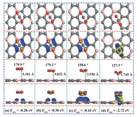
As we all know, the strong interactions of the adsorbates combined with surface contribute to the evident results of gas detection selectivity [54] and sensitivity. In order to enhance the CO2 sensitivity, we apply a forward E-field perpendicular to the Z axis [55] on BC3 surface [52]. The corresponding adsorption configurations were presented in Fig. 1. According to the difference charge density, the adsorption effect gradually increases along with the increasing of the electric field strength. As shown in Fig. 1c, the angle of ∠O-C-O decreased sharply from 180° to 158.6° along with the electric field increased from 0 to 0.006 a.u., and the adsorption distance reduced from 3.10 Å to 2.94 Å. The adsorption energy adds up to ‒0.43 eV, and the charge transfer amount increases to 0.2 e, the charge density expands a lot resulting a stronger chemical adsorption. When the electric field value further increased to 0.008 a.u., the distance between CO2 an-d BC3 suddenly decreased to 1.75 Å, the angle of ∠O-C-O further decreased to 127.3°, and the amount of charge transfer increased to 0.9 e. Seen from the Fig. 1d, the charge density between CO2 and BC3 increased dramatically, resulting that the interaction between the CO2 molecular and the BC3 surface has been greatly improved. These evidences indicate that under an applied electric field of 0.008 a.u., CO2 is chemically adsorbed on the surface of BC3. It is clearly that CO2 is 'fixed' to BC3 surface via employing an electric field. The results indicate the interaction between CO2 and BC3 surface is enhanced, which cause the stronger gas monitoring sensitivity.
Figure 1
Figure 1.
Top and side views of the most favorable CO2 adsorption configurations, corresponding charge density difference in an external E-field of (a) 0.002 a.u., (b) 0.004 a.u., (c) 0.006 a.u., (d) 0.008 a.u.. The blue (yellow) color represents accumulation (diminishing) of electrons. The values of isosurface of (a–c) are 0.003 e/Å3, and (d) is 0.02 e/Å3.
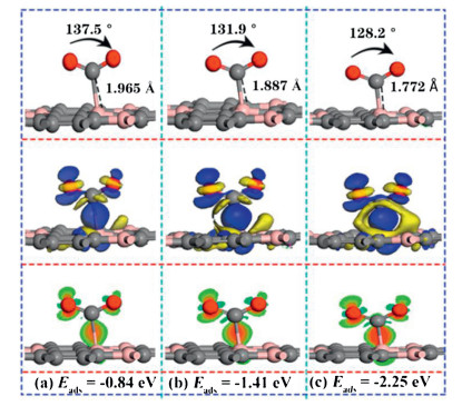
In order to explain the turning point of CO2 adsorption affected by the electric field, three values of electric field (0.0065, 0007, 0.0075 a.u.) were performed to explore the corresponding adsorption structure, adsorption energy and the differential charge density (as shown in Fig. 2). As shown in Fig. S3a (Supporting information), the adsorption distance suddenly decreased from 1.97 Å under the electric field value of 0.0065 a.u., which was 33% shorter than that of values at 0.006 a.u. (2.94 Å). It is noted that the adsorption energy was increased to ‒0.84 eV, which is almost diploid compared with that of ‒0.43 eV. In addition, the angle of ∠O-C-O is reduced to 137.5°, due to the strong interaction of electrons accumulate between CO2 and the substrate, which indicates that can be regarded as strong chemisorption. When the E-field value increased to 0.0075 a.u., the adsorption distance was further shortened to 1.772 Å, the angle of ∠O-C-O was further reduced to 128.2°, and the adsorption energy was increased to ‒2.25 eV, which indicates that the interaction between CO2 and BC3 substrate is further enhanced. The applied E-field will promote the polarization of the charged particles [56, 57], which will lead to the enhanced adsorption of CO2 on the surface of BC3 [55]. As shown in Figs. S3a–c (Supporting information), the critical point of CO2 from physical adsorption to chemical adsorption on the BC3 substrate is between 0.006-0.0065 a.u.. As shown in Fig. S4, the minimum E-field value (0.0065 a.u.) required for the conversion of CO2 from physical adsorption to chemical adsorption is much smaller than that of Penta-graphene [4], and is also smaller than the E-field value required in the previous literature to capture CO2 materials, such as C2N [55], h-BN [27], C3N [58], P-doped C60 [59], P-doped graphene [60]. It is a pity that the value is just slightly larger than that of MoS2 [29] and PC5 [24]. Such as it is, BC3 captures CO2 is more economical and efficient.
Figure 2
Figure 2.
The side view of the most stable configurations and corresponding charge density difference in E-field of (a) 0.0065 a.u., (b) 0.007 a.u., (c) 0.0075 a.u.. The blue (yellow) color represents accumulation (diminishing) of electrons. Red and green represent increasing and decreasing electron density. The values of isosurface of (a), (b), (c) are 0.015 e/Å3, respectively.
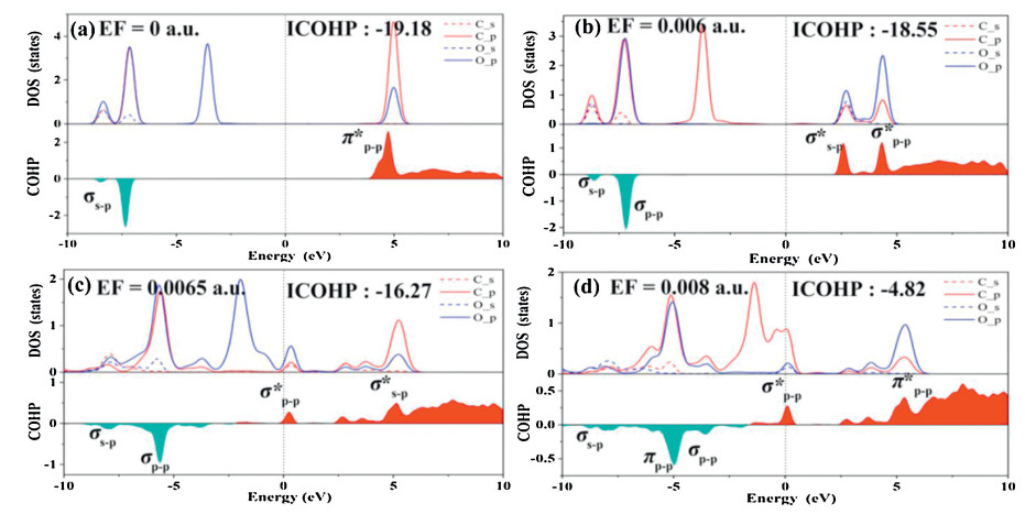
In order to further study the interaction between CO2 and BC3 substrate under different E-field values, partial density of states (PDOS) was studied and presented in Fig. S5 (Supporting information). As shown in Fig. S5, between the E-field value of 0 ~ 0.004 a.u., there is almost no overlap [48] between the orbits of CO2 and B atoms, which indicates that the interaction between them is relatively weak physical adsorption. At this time, the E-field has little effect on the capture of CO2. However, when the E-field value increases to 0.006 a.u., it can be seen that the overall PDOS has a significant right shift, and there is a clear overlapped orbitals of 2p (CO2) and 2p (B) between 3.0 ~ 5.0 eV, indicating the adsorption effect was enhanced, similarly as the previous results [52]. Similarly, when the E-field values at 0.0065 and 0.007 a.u., the orbital overlap formed by the 2p (CO2) and 2p (B) hybrid contributions can appear at ‒5.5, ‒1.2 and 5.0 eV, and the same results can be seen at 0.0075 and 0.008 a.u. It should be noted that the applied E-field can significantly enhance the ability of BC3 to capture CO2.
In order to further study the mechanism of CO2 adsorption on BC3 under an external E-field, the crystal orbital hamiltonian population (COHP) was performed to analyze the different adsorption structures [61-64]. As shown in Fig. 3, the red area is the contribution of the anti-bonding state, and the cyan area is the bonding state. Fig. 3a shows that in the absence of an external E-field, the molecular orbital between C‒O is composed by the σs-p bonding orbital (at ‒6.8 eV) that formed by the interaction of Cs and Op and the anti-bonding π*p-p (at 4.5 eV) formed by the interaction of Cs and Op. In addition, integrated COHP (ICOHP) was calculated to analyze the energy integral up to the highest occupied bands, and the value of ICOHP quantitatively reflected the strength of bonding. As shown in Figs. 3a–d, as the value of the E-field increases, ICOHP gradually decreases, which indicating the weaker of C-O bond in CO2. The reason is that with the increases of the E-field, the interaction between the C of CO2 and B atom is enhanced, inducing the electron cloud more shared with the B atom and a reduction in the overlap of the electron cloud of the C-O, which is accordance with the weakened C-O interaction. Figs. S6a–d show that as the E-field strength increases, the ICOHP between C and B atom increases with the bonding state broaden, indicating that the interaction between C and B is strengthen. It should be highlighted that in the range of 0.0065-0.0075 a.u., the bonding molecular orbital σp-p between C and B atoms is mainly composed by Cp and Bp. Interestingly, bonding molecular orbitals σp-p which located in lower energy contributed by Cp and Bp appeared near the Fermi level.
Figure 3
Figure 3.
PDOS (partial density of states) and molecular orbital of CO2 molecule adsorbed on BC3 under different E-field values, above and below the 0 value of crystal orbital hamiltonian population (COHP) are the anti-bonding state and bonding state, respectively. Red stands for bonding contributions, while cyan stands for antibonding contributions.
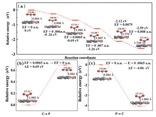
In order to further explore the possible mechanism of CO2 adsorption and desorption on BC3 substrate under the external E-field existence, the potential energy [65] surface was shown in Fig. 4. The energy of the CO2 adsorption system without an E-field is defined as 0. Clearly, the energy of the system gradually decreases along with E-field increases, indicating that the adsorption of CO2 under the external E-field is a spontaneous exothermic process. In addition, when applying 0.006 a.u. E-field, the relative system energy decreases to ‒0.26 eV. It is worth noting that when the external E-field increases to 0.0065 a.u., the relative energy difference immediately decreases to ‒0.69 eV, well consistent with the Eads of ‒0.84 eV, resulting to strong chemical adsorption. Besides, we also systematically studied the capture and separation of CO2 gas on the BC3 substrate by switching the E-field. As shown in Fig. 4b, under the external electric field of 0.0065 a.u., CO2 is chemically adsorbed on the surface of BC3. When the external electric field is turned off, the CO2 adsorption distance is extended from 1.965 Å to 3.264 Å with the CO2 angle shifted from 137.5° to 179.9° after restructuring optimization. The above results demonstrate that the removal of the electric field can promote the transition from chemical adsorption to physical adsorption, in this process the endothermic reaction relative energy value is 0.69 eV. Similarly, when the E-field is switched on, CO2 changed from physical adsorption to chemical adsorption with a linear structure to a V-shaped structure, and the adsorption distance is shortened to 1.965 Å. This process is exothermic process with relative energy ‒4.06 eV without energy barrier. These results shows that the adsorption/desorption of CO2 on the BC3 substrate can be easily controlled by the opening/closing of the electric field.
Figure 4
Figure 4.
The energy profile for the chemisorption to physisorption of the adsorbed CO2 over BC3 due to removing or switching of E-field (EF=0.0065 a.u.).
CH4 and H2 are high-quality energy gases and important raw materials for the manufacture and synthesis of many chemical products. However, in the actual production and processing of CH4 and H2, the presence of CO2 impurities will inevitably be introduced. Therefore, the separation of CO2 from the CO2/H2/CH4 mixed gas is of great research significance for improving the purity of CH4 and H2. In order to evaluate the separation effect of the electric field on the CO2/CH4/H2 mixed gas, we studied the adsorption behavior of BC3 to CO2/CH4/H2 under the E-Field of 0.004 and 0.0065 a.u.. In the external E-Field of 0.004 a.u., the most stable adsorption structure is shown in Fig. S7 (Supporting information). The adsorption distances of CO2/H2/CH4 on the BC3 substrate are 3.032, 2.118, and 2.952 Å, and the corresponding Eads are ‒0.35, ‒0.43 and ‒0.38 eV, respectively. No obvious electron distribution was observed between the CO2/CH4 gas molecules and the substrate. According to the difference in adsorption energy, it can be concluded that H2 can be efficiently separated from the CO2/H2/CH4 mixed gas under the 0.004 a.u.. In addition, the adsorption behaviors of CO2/H2/CH4 gas under an electric field of 0.0065 a.u. has been studied, which is shown in Fig. S8 (Supporting information). Differ from the physical adsorption of CO2/H2/CH4 under no electric field (Fig. S2.), the Eads and Dm of CO2 change significantly (-0.11 to -0.84 eV, 3.371 to 1.965 Å). There is no electron density distribution between the H2/CH4 and the BC3 substrate, but there is a distinct electron density overlaps between the CO2 and the substrate, as shown in Fig. S8. Obviously, the adsorption properties of CO2 and H2/CH4 are different, under this circumstance the former is chemical adsorption and can be captured by BC3, but in fact the latter is physical adsorption.
We used the spin-polarized DFT calculation method to study the adsorption/desorption behavior of CO2 gas with an external Z-axis vertical positive electric field. An external electric field vertical to the BC3 surface can significantly enhance the interaction between CO2 and the substrate. In particular, in the range of 0.006-0.0065 a.u. electric field value, CO2 shifted from BC3 physisorption on C4B2 vacancy with the rapid decrease of Eads by 663% (‒0.11 to ‒0.84 eV). Desorption of chemisorbed CO2 occurred from the BC3 surface without passing any energy barrier and released an energy of 0.69 eV when the E-Field is switched off. Utilizing the difference in the adsorption properties of CO2/CH4/H2 on BC3 under the E-Field value of 0.004 and 0.0065 a.u., H2 and CO2 gas can be separated from the CO2/H2/CH4 gas mixture. These results confirmed that BC3 is a potential material for capturing CO2 under external electric field.
Declaration of competing interest
The authors declare that they have no known competing financial interests or personal relationships that could have appeared to influence the work reported in this paper.
Acknowledgments
This study was funded by the National Natural Science Foundation of China (No. 21603109), the Henan Joint Fund of the National Natural Science Foundation of China (No. U1404216), the Scientific Research Program Funded by Shaanxi Provincial Education Department (No. 20JK0676).
Figure 1
Top and side views of the most favorable CO2 adsorption configurations, corresponding charge density difference in an external E-field of (a) 0.002 a.u., (b) 0.004 a.u., (c) 0.006 a.u., (d) 0.008 a.u.. The blue (yellow) color represents accumulation (diminishing) of electrons. The values of isosurface of (a–c) are 0.003 e/Å3, and (d) is 0.02 e/Å3.
Figure 2
The side view of the most stable configurations and corresponding charge density difference in E-field of (a) 0.0065 a.u., (b) 0.007 a.u., (c) 0.0075 a.u.. The blue (yellow) color represents accumulation (diminishing) of electrons. Red and green represent increasing and decreasing electron density. The values of isosurface of (a), (b), (c) are 0.015 e/Å3, respectively.
Figure 3
PDOS (partial density of states) and molecular orbital of CO2 molecule adsorbed on BC3 under different E-field values, above and below the 0 value of crystal orbital hamiltonian population (COHP) are the anti-bonding state and bonding state, respectively. Red stands for bonding contributions, while cyan stands for antibonding contributions.
Figure 4
The energy profile for the chemisorption to physisorption of the adsorbed CO2 over BC3 due to removing or switching of E-field (EF=0.0065 a.u.).

 DownLoad:

 下载:
下载:


