Center for Computational Chemistry and Molecular Simulation, College of Chemistry and Chemical Engineering, Southwest Petroleum University, Chengdu 610500, China
b.
Department of Chemical and Biological Engineering, Case Western Reserve University, Cleveland, OH 44120, United States
zhanghuiswpu@163.com (H. Zhang). 1 These authors contributed equally to this work.
Received Date:
21 May 2020 Accepted Date:
05 August 2020 Revised Date:
06 July 2020 Available Online:
15 October 2020
Abstract:
Macroporous 3D carbon doped with nitrogen confined Mo catalyst (MoOx@CN) had been prepared by a facile one-step pyrolysis technique using silica as a template and was employed for oxidative desulfurization (ODS) of dibenzothiophene (DBT) in model fuel with H2O2 as oxidant. The effect of different operating conditions (i.e., reaction temperature and time, catalyst dosage, H2O2/DBT (O/S) molar ratio) were also systematic investigated. Under the optimal reaction condition, MoOx@CN catalyst exhibited highly excellent ODS performance toward DBT, the highest sulfur removal efficiency can be up to 99.9% and sulfur content was wiped out from 800 ppm to 10 ppm. Due to the robust 3D structure promoting rapid transfer, in addition to the increased number of active sites induced by the Mo vacancies, the catalyst, prepared using chitosan and ammonium heptamolybdate in a mass ratio of 1:0.5, displayed rapid kinetics and low activation energy in the oxidation of dibenzothiophene. Moreover, it exhibited excellent recyclability after five cycles without any obvious decrease in catalytic activity for the oxidative desulfurization reaction.
Currently, fossil-derived fuels play an important role in the global economy [1]. However, noticeable amounts of sulfurcontaining organic compounds, such as thiophene (Th), benzothiophene (BT), dibenzothiophene (DBT), and dimethyldibenzothiophene (DMDBT) are commonly present in fossil-derived transport fuels [2]. Due to ongoing requirements for reducing the sulfur content of such fuels, deep desulfurization has received increasing attention from the international community, since the presence of such sulfur-containing compounds results in the production of an exhaust gas containing sulfate particulates, which in turn can threaten both the environment and human health [3]. The desulfurization of transport fuel is therefore an urgent scientific issue that requires an adoptable solution [4].
To date, a series of methods, including hydrodesulfurization (HDS) [3, 5], adsorption [6-10], biodesulfurization [10], and oxidative desulfurization (ODS) [11-17], have been investigated to minimize the S-content of transport fuels. More specifically, traditional HDS is an industrial refining process that tends to require harsh conditions, such as a high temperature (300-400 ℃), a high pressure (10-130 atm), and excessive H2 consumption, to reduce the levels of organosulfur compounds (OSC) [18-20]. Although current HDS technologies can effectively remove aliphatic sulfur compounds, the low hydrogenation activity [20, 21] leads to the ineffective removal of refractory aromatic substrates, such as Th, BT, and DBT. The development of non-HDS-based desulfurization methods is therefore desirable.
In this context, ODS is a promising method for desulfurization as it does not require the use of hydrogen, and it has been shown to efficiently treat aromatic sulfides [21]. The ODS process typically involves two steps, where the first step involves oxidation of the sulfur-containing molecules in the fuel to provide the corresponding sulfoxides or sulfones by employing an oxidant in the presence of a suitable catalyst [22]. Indeed, the removal of such oxidation products from fuel oils is relatively facile by adsorption or solvent extraction methods in the second step of this process [12]. The most commonly studied oxidants for this purpose are hydrogen peroxide, organic hydroperoxides (such as t-butyl hydroperoxide, TBHP) [23], molecular oxygen [15, 24] and ozone [15]. Indeed, hydrogen peroxide [16, 25] is a key oxidant for the removal of sulfur compounds under eco-friendly conditions, due to its ready availability, its high concentration of active oxygen species (47%), and the fact that only water is produced as a by-product [26].
Thus, to address both the energy and environmental issues associated with the removal of sulfur-containing compounds from fuels, the development of highly active and selective catalysts is necessary. For example, molybdenum-containing catalysts have received significant attention [13, 27, 28]. Besides, many studies have revealed that the introduction of defects in such catalytic materials can increase the number of intrinsic active sites, thereby improving the catalytic performance [29-33].
Inspired by the above-described studies, we herein report a simple, convenient, and cost-effective protocol for the design and synthesis of a series of MoOx nanoparticles, rich in Mo vacancies, and uniformly anchored on N-doped three-dimensional macroporous carbon net structure (3D MoOx@CN). These materials will then be evaluated in the context of their oxidative desulfurization properties, and the role of Mo vacancies on active site production and the resulting ODS capability will be examined. Defect engineering, as an effective strategy to improve catalytic activity, is rarely studied in the field of ODS, so this aspect has great prospects. In addition, the role of the 3D macroporous carbon net structure in enhancing the accessible surface area and producing mass transfer channels for the permeation of sulfur compounds and transportation of oxidation product will be studied in this paper using the model fuel. The proposed route for the preparation of the desired MoOx@CN materials is outlined in Fig. S1 (Supporting information).
All chemicals and analytical methods were provided in Text S1 (Supporting information). Macroporous 3D carbon-nitrogen confined MoOx catalyst (MoOx@CN) was prepared by one-step pyrolysis technique, which was depicted in Fig. S1, reported in previous publication [34]. For the catalyst synthesis, 1 g chitosan and 3.0 g self-prepared silica sphere were orderly dissolved in 200 mL deionized water with 2 mL acetic acid. After that, 10 mL ammonium heptamolybdate (AHM) solution (50 mg/mL) was slowly added in the solution with a stirring for pyrolytic reaction. After the reaction completed, the resulting mixture was dried at 80 ℃ under stirring, and a powder was obtained by grinding using a mortar and pestle. Then calcined in Ar flow of 20 mL/min at 750 ℃ for 6 h. Finally, the obtained black product was washed with a certain amount of hydrofluoric acid (HF) to fabricate the macropores by the removal of silica at room temperature. According to the different mole ratios of chitosan/ammonium heptamolybdate (C/A), the synthesized samples were denoted as MoOx@CN-1 (C/A = 1), MoOx@CN-2 (C/A = 2), MoOx@CN-4 (C/A = 4).
The catalytic ODS experiments were conducted in a 50 mL three-necked flask with magnetic stirring at a water bath and fitted with condenser. 0.82 g DBT was dissolved in 250 mL n-octane as a model oil with sulfur content of 800 ppm for ultrasound 30 min. In a typical run, 30 mL model diesel oil and 6 mL methyl cyanide as extracting agent were added to the reactor then stirred 15 min to achieve extraction equilibrium. Next a certain amount of catalyst and 0.15 g H2O2 (molar ratio of H2O2/DBT (O/S) = 5) were added into above solution and stirred quickly to disperse evenly. Reaction temperature was set range from 0 ℃ to 60 ℃. After 75 min reaction, a certain amount of sample was taken out and centrifuged at 8000 rpm for 3 min to obtain phase separation, and the oil phase with sulfides was analyzed by gas chromatography (GC, SP-6890) with flame ionization detector (FID). Sulfur removal efficiency (y) was calculated as follows (Eq. 1):
(1)
where C0 is the initial sulfides concentration (ppm) in the oil, Ct is the sulfides concentration (ppm) in the oil phase at time t.
The SEM images of silica, silica polymer composite and the sample after the removal of silica were shown in Fig. S2 (Supporting information). It was clearly found spherical silica with uniform size of 190 nm. The removal of silica using HF solution lead to the formation of macropores on carbon with highly uniform pore size from SEM images in Fig. S2d. Macropores carbon with highly uniform pore size was fabricated successfully at the current condition.
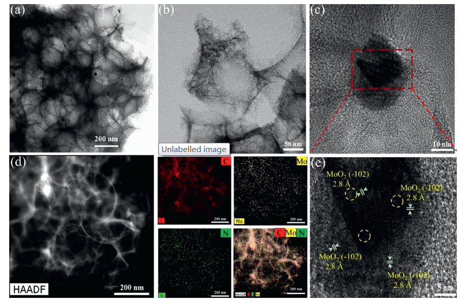
To further obtain the structural information, HRTEM characterization was employed, which was shown in Fig. 1. As shown in transmission electron microscopy (TEM) (Fig. 1a) and high-angle annular dark field scanning transmission electron microscopy (HAADF-STEM) (Fig. 1d) images, macropores carbon materials with three-dimensional structure (pore size ~190 nm) could be clearly detected and exhibited a diameter of 27.7 ± 9.9 nm of MoOx species over MoOx@CN-2 catalyst in Fig. S3 (Supporting information). In addition, the high-resolution TEM image (Fig. 1e) illustrates a lattice spacing of ~0.28 nm, which corresponds to the (-102) facet of MoOx. Moreover, it should be noted that the existence of part discontinuous lattice (point defects, yellow-dot circle in Fig. 1e). Such discontinuous lattice is considered to be created by the defect that has been widely reported in the field of crystallography [32, 35]. The elemental mapping (Fig. 1d) showed that C, N, and Mo were homogeneously distributed throughout the 3D MoOx@CN-2 structure, therefore verifying the uniform distribution of MoOx nanoparticles on N-doped three-dimensional macroporous carbon net structure.
Figure 1
Figure 1.
TEM images of different magnifications of MoOx@CN-2 (a–c). (d) HAADF image of MoOx@CN-2; corresponding elemental mapping of Mo, N, and C, and overlapping of Mo, N, and C. (e) HRTEM image of the MoO2 (-102) interplanar spacing of MoOx@CN-2.
Fig. S4a (Supporting information) displayed X-ray diffraction (XRD) patterns of MoOx@CN-1, MoOx@CN-2, MoOx@CN-4 catalysts. All the peaks of MoOx@CN samples were almost indexed to the characteristic peaks of MoO2 (PDF #73-1249). By calculating from Scherrer equation, the average particle sizes of three samples were 43.1 nm, 34.9 nm, 24.6 nm respectively for MoOx@CN-1, MoOx@CN-2 and MoOx@CN-4 that is estimated from the (-011) and (-211) intensity diffraction peaks (see the calculation details in the Supporting information). As we can see from the results, the average particle size is linearly proportional to the amount of ammonium heptamolybdate.
The identification of different molybdenum species in synthesized catalysts was characterized by Raman spectroscopy, which was displayed in Fig. S4 (Supporting information). As shown in Fig. S4b, three samples MoOx@CN-1, MoOx@CN-2, MoOx@CN-4 exhibited two broad characteristic peaks at 1311 cm-1 (D band) and 1594 cm-1 (G band), which are attributed to the crystal defect and graphitic lattice vibration mode with E2g symmetry, respectively [34]. In addition to the carbon peaks, there are several other peaks at 661, 814, 970 cm-1, which are deviated from the characteristic peak of MoO2 and could be assigned to MoO3 [36]. Combined with the XRD result, it shows that there are abundant Mo vacancies in MoOx with x = 2–3.
X-ray photoelectron spectroscopy (XPS) analysis of MoOx@CN-2 was shown in Fig. S5 (Supporting information), to further determine the composition and surface chemical state of Mo. As shown Fig. S5a, the survey spectrum involved distinct peaks at 232.2, 284.8, 398.2, 415.2, and 530.2 eV, which could be readily assigned to Mo 3d, C 1s, N 1s, Mo 3p1/2, and O 1s, respectively. In Fig. S5f, high-resolution XPS Mo 3d spectrum indicated that there are three valence states of Mo4+, Mo5+, Mo6+ on the surfaces of the MoOx@CN-2. The peaks at Mo 3d5/2 (229.7 eV) can be attributed to the Mo4+. The banding energy (BE) around Mo 3d5/2 (230.69 eV) corresponded to the Mo5+. The BE at Mo 3d5/2 (232.6 eV) belonged to the Mo6+ [37]. The presence of the Mo5+ and Mo6+ might be attributed to the generation of Mo vacancies during the elimination of the SiO2 template and breakage of the Si-O-Mo bond[32, 34, 38]. Because the Mo6+ were designed with changed chargedensity distribution, the Mo6+ sites were predicted to be more active to interact with H2O2 [39]. In addition, the detailed element contents were listed in Table S2 (Supporting information). It can be noted that the Mo6+ content of MoOx@CN-1, MoOx@CN-2, and MoOx@CN-4 were estimated to be 14.89%, 16.54%, and 14.51%, respectively, indicating more active sites in the MoOx@CN-2 than MoOx@CN-1 and MoOx@CN-4. In the N 1 s spectrum (Fig. S5g), the main peaks at 398.1 and 401.1 eV were assigned to pyridinic N and graphitic N, respectively [34]. In Fig. S5h, the peaks at 284.8 in the C 1s spectrum can be attributed to C—C present in MoOx@CN-2 and those at 285.9, 288.1 eV can be ascribed to C—O—C bonds, O—C = O bonds, respectively [31]. As shown in Fig. S5i, the O 1s signal showed three divided peaks at 530.5, 531.8, 533.3 eV belonging to Mo—O bonds, C—O bonds, and H—O—C bonds [37], respectively.
As shown in Fig. S6a (Supporting information), the possibility of an effective collision between the catalyst and the oxidant is small at lower reaction temperatures, and thus the desulfurization performance is poor. Indeed, at 10 ℃ and 20 ℃, the oxidative desulfurization efficiency reached only 51.42% and 68.73%, respectively, after 60 min. Upon increasing the reaction temperature to 50 ℃, the desulfurization conversion was significantly improved, reaching 100%, and so this temperature was selected as the optimal reaction temperature. The amount of oxidant employed was also found to play a significant role in the ODS process. More specifically, the effect of the O/S ratio on the ODS of DBT for the MoOx@CN-2 sample was investigated based on the optimized experimental conditions. According to stoichiometric calculations, 2 mol of H2O2 are required to oxidize 1 mol of the sulfur-containing compound (DBT) into its corresponding sulfone (DBTO2). Indeed, we found that the removal rate of DBT increased from 77.11%–100% upon increasing the O/S ratio from 1:1 to 5:1 in Fig. S6b (Supporting information), and so the latter was selected for the following oxidation-extraction desulfurization process.
The influence of reaction time on the ODS process was then examined as depicted in Fig. S6c (Supporting information), where it is apparent that the performances of the MoOx@CN-2 catalysts were clearly time-dependent.More specifically, with a reaction time of 15 min, a DBT conversion of 89.24% was achieved for MoOx@CN-2, and thisincreased to 100% after 60 min. As such, a reaction time of 60 min was selected for the following oxidation runs.
We then moved on to examine the effect of the catalyst dosage using MoOx@CN-2 at 50 ℃ over 1 h, and with an O/S ratio of 5:1 for the ODS process. As shown in Fig. S6d (Supporting information), a catalyst loading of 0.005 g has lower DBT conversion at 90.09%. However, upon increasing the catalyst loading to 0.01 g, the sulfur removal yield (for DBT) increased significantly, with the complete removal of DBT being observed. A MoOx@CN-2 loading of 0.01 g was therefore employed for subsequent reactions.
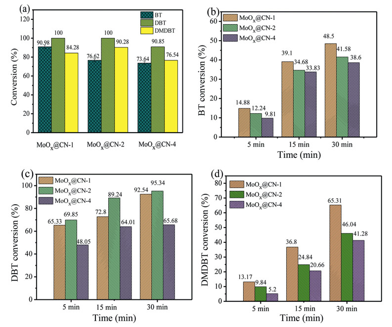
As seen in Table S3 (Supporting information), the nature of the substrate itself is a significant factor in determining the desulfurization efficiency. Although DBT is a representative sulfur-containing compound present in transport fuel, other sulfur-containing compounds must also be evaluated for desulfurization, since their presence has an effect on the ODS reaction. It is therefore necessary to investigate the efficiency of the oxidation of other sulfur-containing heteroaromatics, such as BT and DMDBT. As shown in Fig. 2a, the conversions of the three sulfur-containing heteroaromatics follow the order: DBT > 4, 6-DMDBT > BT. Within 30 min (Figs. 2b–d), the highest removal rates of DBT by MoOx@CN-2 and 4, 6-DMDBT by MoOx@CN-1 were 95.34% and 65.31%, respectively, while in the case of BT, its corresponding removal efficiency reached only 48.50% using MoOx@CN-1. This was attributed to the relatively low electron cloud density (5.739) on the S atoms of BT, compared to those of DBT and 4, 6-DMDBT (5.758 and 5.760, respectively) [40], which appears to influence the desulfurization activity. Compared to DMDBT, the rate constants for the oxidation of BT and DBT over MoOx@CN are greater, which corresponds with their associated electron densities (Tables S3 and S4 in Supporting information). In the cases of DBT and 4, 6-DMDBT, the difference in the electron cloud density on the S atom is small, and so the different desulfurization activities were attributed to steric hindrance originating from the methyl groups on the benzene rings [41] of 4, 6-DMDBT (Scheme S1 in Supporting information). Such steric hindrance renders oxidation of the S atom difficult, resulting in a slightly lower desulfurization efficiency for 4, 6-DMDBT compared to DBT.
Figure 2
Figure 2.
(a) Conversions of BT, DBT, and DMDBT at 50 ℃ using the three MoOx@CN catalysts (catalyst weigh = 10 mg, O/S = 5:1, reaction time = 75 min). (b–d) Conversions of BT, DBT, and DMDBT at 50 ℃ using the three MoOx@CN catalysts with a reaction time of 30 min.
The reusability of any catalyst is critical for its commercial application. Thus, to determine the stability of catalyst, thereusability of MoOx@CN-2 for the oxidation of DBT in the ODS reaction was investigated over five runs. Following each catalytic run, the heterogeneous MoOx@CN-2 catalyst was easily recovered by centrifugation, then washed with acetonitrile to remove the sulfone product. The recovered catalyst was reused over four cycles under similar conditions (Fig. S7 in Supporting information). In the fifth run, the conversion of DBT was slightly reduced to 93.81%, which was likely due to the loss of catalyst mass during recovery and a degree of catalyst deactivation through the adsorption of sulfur-containing substrates or products. The XRD patterns of the recycled MoOx@CN-2 catalyst after the first and fifth cycles (see Fig. S8 in Supporting information) showed little variation to the fresh catalyst, further confirming the stability of the MoOx@CN-2 catalyst. The high catalytic performance and reusability of MoOx@CN-2 thereby render it a promising catalyst for application in ODS reactions.
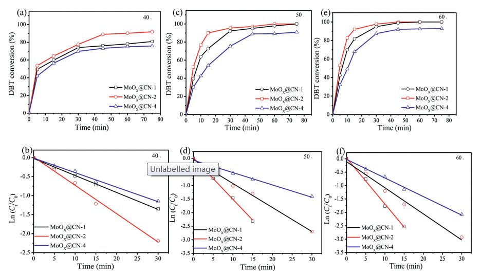
As shown in Fig. 3, the ODS kinetic parameters in the presence of the as-prepared catalysts were then investigated based on the pseudo-first order model (reaction temperature = 50 ℃, reaction time = 30 min). The kinetic constant k (min-1) was calculated by plotting ln (Ct/C0) against t as follows (Eqs. 2–4):
(2)
(3)
(4)
Figure 3
Figure 3.
Effect of reaction temperature on the conversion of DBT at (a) 40 ℃, (c) 50 ℃, and (e) 60 ℃ using MoOx@CN (catalyst weight = 10 mg, O/S = 5:1, reaction time = 75 min). Pseudo-first order kinetic plots for the oxidation of DBT over MoOx@CN-1, MoOx@CN-2, and MoOx@CN-4 at (b) 40 ℃, (d) 50 ℃, and (f) 60 ℃, respectively.
where Co and Ct are the concentration of DBT at the initial and corresponding reaction times, t (min), respectively. According to Eq. 4, a linear relationship between ln (Ct/C0)and t was found, as shown in Fig. 3d. Thus, due to the good correlation parameter (R2) achieved by this linear fit, the obtained data were concluded to follow the pseudo-first order kinetic model effectively. We also found that MoOx@CN-2 exhibited the highest kinetic constant as shown in Table 1, thereby suggesting that MoOx@CN-2 is the most effective of the prepared catalysts described herein.
Table 1
Table 1.Pseudo-first order rate constants and correlation factors for the oxidation of DBT at different temperatures.
In order to further study the relationship between reaction temperature and activation energy over the developed MoOx@CN catalysts, the oxidative desulfurization of DBT in a model fuel was performed at different temperatures (i.e., 40, 50, and 60 ℃) as shown in Figs. 3a, c and e. With the increase of reaction temperature, the conversion rate of DBT gradually increased.
The relationship between k and the reaction temperature was also found to obey the well-known Arrhenius equation (Eq. 5):
(5)
As Fig. S9 (Supporting information) shows the Arrhenius plots for the oxidation of DBT on the constructed catalysts at various temperatures. Calculations revealed that the activation energies (Ea) of the reactions involving MoOx@CN-1, MoOx@CN-2, and MoOx@CN-4 were 43, 38, and 49 kJ/mol, respectively (Table 1). According to results for the kinetic constants (Table 1), the highest kinetic constant was observed for MoOx@CN-2, which is consistent with the low Ea value. These results confirm that the efficiency of the catalyst improves with lower activation energies [12]. More specifically, using 1 g of each prepared catalyst, the conversion rates of DBT to DBTO2 were 97.89%, 100%, and 89.22% over MoOx@CN-1, MoOx@CN-2, and MoOx@CN-4, respectively (Table 2 [19, 42-44]). It was therefore apparent that the MoOx@CN-2 catalyst exhibited the highest kinetic constant (1.5 × 10⁻¹) and the lowest activation energy (38 kJ/mol) of the various catalysts, thereby rendering it the most effective for the oxidation of DBT. And then compared with previously reported results (Table 2), MoOx@CN exhibits a superior performance in the elimination of DBT with the assistance of hydrogen peroxide.
Table 2
Table 2.
Oxidative desulfurization of DBT over the various catalysts using H2O2 as an oxidant with different reaction parameters.
According to the literature [39] and experimental results, a reasonable reaction mechanism of MoOx@CN catalyst with abundant Mo vacancies can be proposed. H2O2 and DBT are adsorbed on the catalyst due to the adsorption of CN material; The Mo6+ species which were generated by molybdenum vacancies extremely lacking in electrons enhance the adsorption of H2O2, and react with H2O2 as the active centers, then produce superoxide-molybdenum species; The superoxide-molybdenum species, oxidize DBT to DBTO2; When the DBT takes away the oxygen in the molybdenum peroxide, molybdenum vacancies are generated again.
To sum up, we herein proposed a facile method for the preparation of molybdenum oxide nanoparticles incorporated with abundant Mo defects and supported on a three-dimensional macroporous nitrogen-doped carbon net structure (3D MoOx@CN) for use as a promising commercial potential oxidative desulfurization (ODS) catalyst. The 3D macroporous carbon net structure effectively exposed a large accessible surface area and rapid mass transfer channels for the ODS process. Due to being the introduction of molybdenum vacancies during the leaching step, Mo6+ species were generated and increasing the number of catalytically active sites. The obtained 3D MoOx@CN-2 catalyst which has more Mo6+ species than MoOx@CN-1 and MoOx@CN-4 exhibited a superior activity for the desulfurization of dibenzothiophene in a model fuel, with low activation energy, fast kinetic constant, and high catalyst throughput. It also exhibited excellent recyclability after five cycles without any obvious decrease in catalytic activity. This article, therefore, expands the applicability of the ODS reaction based on the use of molybdenum vacancies catalysts and provides new opportunities for the development of efficient desulfurization catalysts for a range of applications.
Declaration of competing interest
The authors report no declarations of interest.
Acknowledgment
This work was supported by the Applied Basic Research Project of Science and Technology Department of Sichuan Province (No. 2020YJ0418).
M. Zhu, G. Luo, L. Kang, B. Dai, RSC Adv. 4(2014) 16769-16776. doi: 10.1039/C4RA01367K
Figure 1
TEM images of different magnifications of MoOx@CN-2 (a–c). (d) HAADF image of MoOx@CN-2; corresponding elemental mapping of Mo, N, and C, and overlapping of Mo, N, and C. (e) HRTEM image of the MoO2 (-102) interplanar spacing of MoOx@CN-2.
Figure 2
(a) Conversions of BT, DBT, and DMDBT at 50 ℃ using the three MoOx@CN catalysts (catalyst weigh = 10 mg, O/S = 5:1, reaction time = 75 min). (b–d) Conversions of BT, DBT, and DMDBT at 50 ℃ using the three MoOx@CN catalysts with a reaction time of 30 min.
Figure 3
Effect of reaction temperature on the conversion of DBT at (a) 40 ℃, (c) 50 ℃, and (e) 60 ℃ using MoOx@CN (catalyst weight = 10 mg, O/S = 5:1, reaction time = 75 min). Pseudo-first order kinetic plots for the oxidation of DBT over MoOx@CN-1, MoOx@CN-2, and MoOx@CN-4 at (b) 40 ℃, (d) 50 ℃, and (f) 60 ℃, respectively.


 DownLoad:


 下载:
下载:


