Figure 1.
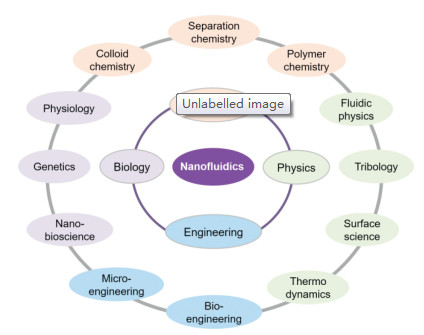
Classical disciplines and relevant subjects related to nanofluidics.
Ionic current rectification in asymmetric nanofluidic devices
Yue Zhou , Xuewei Liao , Jing Han , Tingting Chen , Chen Wang

Over the past 3 decades, microfluidics have been greatly developed and widely used in various fields [1-6]. With the upcoming of nanotechnology, researchers hope to study fluidics and the molecular behavior at the nanoscale. Then nanofluidics was born, which is concerned to many classical disciplines such as biology, chemistry, physics, engineering (Fig. 1) [7-24]. In addition to the geometrical scaling-down, there are many new phenomena involved in this new field, among which the ionic current rectification (ICR) is a unique mass transport behavior occurring in asymmetric nanofluidic devices. ICR is defined as a non-linear diode-like current-voltage (I–V) behavior in nanochannel, i.e., the departure from Ohmic behavior [25-37]. The phenomenon of ICR was first observed in quartz nanopipet electrodes [25] and later studied extensively with conically shaped nanopores in polymer membranes [32]. The rectification property is characterized by the rectification ratio, which is the ratio of forward-bias current to reverse bias current.
In recent years, growing attention has been paid to nanofluidics and some excellent literatures concerning this discipline are available [8, 11, 38-46]. Inspired by the unique asymmetric transport of ICR, nanofluidics has already found tremendous applications in various fields including energy conversion, mass separation, sea water purification and bioanalysis over the past several years [7, 8, 25, 47-54]. An updated review on ICR in nanofluidic devices is highly desired. This perspective is intended to achieve such a goal, and is organized as follows: The first section is the introduction part; The second section discusses the mass transport behaviors in nanofluidic devices; The third section describes the generation mechanism and fundament of ICR in nanofluidics; The forth section summarizes the factors influencing and determining the ICR property of nanofluidics; Finally, the short conclusion of this review and the current challenges towards the development of ICR are provided in the conclusion part.
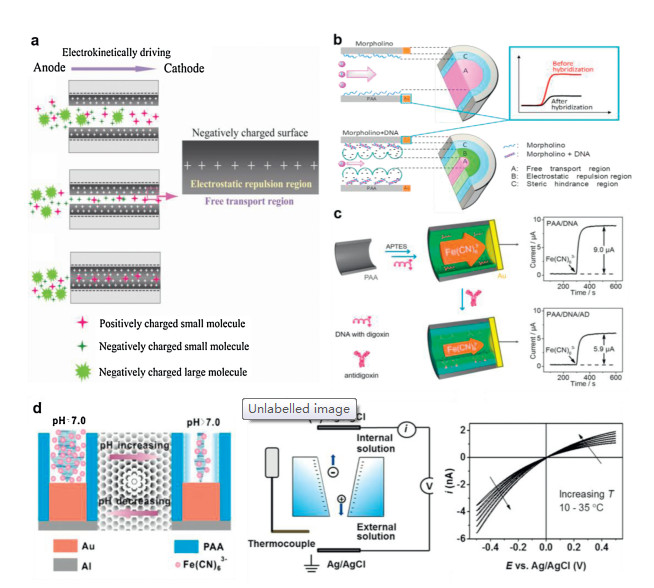
The mass transport in nanofluidics is mainly decided by the charge effect and size effect of nanochannel. In nanochannel, electric double layer (EDL) thickness is comparable to the characteristic channel dimensions, causing many unique properties markedly different from micro- and macro-systems. As illustrated in Fig. 2a, the nanochannel can be divided into electrostatic interaction region and free transport region. The nanochannel with relative larger size enables co-exist of electrostatic interaction region and free transport regions. Under this circumstance, the mass transfer (J) across the nanochannel can be descried by the Nernst-Planck equation (Eq. 1), which we have been discussed previously [11, 55],
|
|
(1) |
where, 

Using the concept of the charge effect and size effect of nanofluidics, Xia's group achieved label-free DNA analysis using array nanochannels. The electroactive probes of Fe(CN)63– was used for monitoring the reaction kinetics in real-time, which could be detected by an electrochemical detector (Fig. 2b) [56]. They first immobilized morpholino (a neutral analogue of DNA) on the nanochannel walls. Before and after DNA-morpholino hybridization, the flux of Fe(CN)63– flowing through nanochannels would change owing to the changed free space for mass transport. Based on the varied electrochemical current, the DNA detection could be performed in a label-free format. Results showed that this nanochannel-based biosensor could achieve a detection limit of 0.1 nmol/L. Furthermore, the kinetics of biological reaction and protein aggregations could also be investigated by monitoring the probe flux in real-time [57-61], and the confinement effect on the biomolecular recognition events was revealed (Fig. 2c) [58]. In a recent work, the mass transfer property in nanochannels was tuned by changing the pH values (Fig. 2d) [62]. The changed pH value led to varied surface charge distribution of nanochannels, and then influence the ions flux through nanochannels. By measuring the flux of the electroactive probe through nanochannels, the pH-regulated mass transport in nanochannels could be accurately detected. These works demonstrate the promising applications of nanofluidics in the fields of analytical chemistry and biological science.
Specially, if the devices are asymmetric, and the EDL is overlapped in some regions in nanochannels, the selective molecule/ion transport will occur, which gives rise to unique ICR characteristic (Fig. 2e) [16, 63]. Taking advantage of the ICR property, diverse applications have been explored using nanofluidic devices. For example, energy conversion and sea water purification systems can be constructed based on selective ions transport of nanofluidic devices [22], which is expected to provide a new strategy for addressing the worldwide energy crisis. Controllable mass transport and separation can be achieved by tuning the size and surface properties of nanochannels [22], which is of great significance to the development of green chemistry. Biosensors based on nanopore/nanochannels can provide sensitive and label-free analysis for biomolecules and cells, which is of critical importance in the fields of bionalysis and clinic detections [64]. In the following part, we will focus this review on the fundamental of ICR including the generation mechanism and influencing factors in asymmetric nanofluidic devices.
Despite the dramatical progresses have been made in ICR including the devices design and fundamental studies in recent years, the debate still persists concerningits origination mechanism. So far there are two typically basic explanationsfororigin of ICR. One is the "ratchet" mechanism, which is based on electrokinetic trapping of mobile ions in asymmetric nanochannel (Fig. 3a) [32]. This model attributes the low conductance state to a potential well near the tip of the conical pore which traps ions and decreases current flow. In comparison, if the external electric field is applied in an opposite direction, there is no potential well existing, and thus a high conductance state is expected. The presence of the potential well has been confirmed in numerical simulations within nanopores [65]. An alternative theory for ICR holds that rectification arises from difference in transference numbers around the tip of the nanopore [66]. At the tip of the pore, a large proportion of the current is carried by counterions. Further into the pore, the counterion transference number decreases. When counterion transport is from tip to base, it moves from a high transference number region near the tip to a low transference number region near the base, resulting in counterions accumulationwithin the pore. The increased ion concentration leads to a high conductance state (high G in Fig. 3b). When the field is applied in the opposite direction, counterions travel from base to tip, which may be removed more quickly than they are replenished, resulting in decreased ion concentration within the pore and accordingly lower conductance (low G in Fig. 3b). The typical I–V characteristicsof a single conicalnanoporewas shownin Fig. 3b.Itis obvious that smaller pores have higher cation selective and larger rectification ratio. This theory has been predicted by calculations based on a membrane model with narrow pores [67], as well as by numerical analysis of the Poisson-Nernst-Planck equations [68].
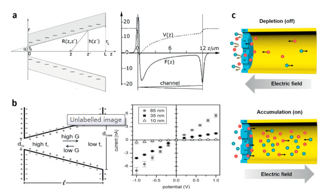
Actually, these two explanations for ICR mechanism are essentially the same. In a very recent work, Wang et al. revealed the ICR mechanism using ions enrichment and depletion theory in nanochannel (Fig. 3c) [69]. They used experimental result and the Finite Element model to study the potential distribution along the nanochannels. It was found that under positive bias, the anions are impeded from entering the ionchannels. In this case the cations passing through the nanochannels are slowed down in order to keep the electrical neutrality of the whole channels. Accordingly, the number of both cations and anions are very limited, resulting in ions depletion and "off" state of nanohcannels. When the potential is applied reversely, both cations and anions will accumulate inside nanochannels, and the ionic current turns to "on" state.
Up to now, several types of nanofluidic devices have been reported to have ICR properties including asymmetric channel geometry, surface charge distribution, bath concentrations, and outer surface charges. Recently, the origin of ICR was deeply studied using a DNA-stuffed nanochannels [70]. By breaking and retrieving symmetry of the nanochannels, an appropriate and quantified for ICR measure is provided. The finding shows implications to asymmetric transport phenomena for future innovative nanofluidic devices. In the following part, we present the different nanofluidic devices of each aspect, and explained the contribution of mass transport on the ICR property.
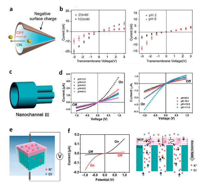
A conical nanopore is a common nanofluidic device that utilizes asymmetric geometry to rectify ion currents [25, 71-79]. Prepared by irradiating heavy ions on polyethylene terephthalate (PET) following by subsequent chemical etching, a conical nanopore with a diameter tip and a larger diameter base can be achieved, as described in Fig. 4a [71]. The authors investigated the ionic transport properties through the nanochannels and found that the ICR can be achieved under different KCl concentrations and pH values (Fig. 4b). The rectification ratio could be achieved as high as more than 100. Similarly, Wei and his co-workers reported the ICR in a quartz nanopipette, which is pulled from a clean quartz tube using a microprocessor-controlled CO2 laser puller [25]. Due to the existence of a diffuse EDL within the tip orifice, the nanopipette exhibites remarkable asymmetric ion conductance behavior. Asymmetric nanopores could also be fabricated by directly exposing the nanopore of ~100 nm diameter under an argon beam at room temperature. The pore on one side closed gradually, forming nanopores with diameter of ~1.8 nm [72]. The asymmetric pore size yields high rectification of ion current. Recently, a new ionic current rectification device with branching nanochannel array was fabricated using porous anodic alumina (PAA) membrane (Fig. 4c) [73]. In varied pH environments, the protonation/ deprotonation of the intrinsic hydroxyl groups in nanochannels array occurs, which enables to regulate the ICR properties facilely (Fig. 4d). A 3D model for reflecting the ions transport in the device was used to study the rectification ratio. It was found that the ICR of the device is dominated by the branching size and surface charges. In another work, a nanofluidic ICR device was fabricated using porous anodic alumina (PAA) nanochannels and graphene oxide via dopamine polymerization. The asymmetric nanostructure results in obvious ICR. Via finite element simulation, it is proved that the interface distance and surface charge play a vital role in ion transport [74]. Very recently, a hybrid nanofluidic device was constructed by in-situ synthesizing 2D metal-organic frameworks (MOFs) on PAA surface (Figs. 4e and f) [78]. The asymmetry in the geometry and chemical composition of present device enables it with an outstanding ICR property. With the advantages of facile fabrication process and high ICR ratio, the prepared MOFs/PAA hybrid nanochannel offers a promising candidate for bioanalysis and power storage/conversion.
The asymmetric channel geometry leads to asymmetric surface charge distribution along the nanochannels. In the region of EDL overlap, the co-ions are blocked while the counter ions can be allowed to enter the channel. This selective ion transport gives rise to the ion enrichment and depletion phenomena under varied potential polarity (as illustrated in Fig. 3c), which contribute to the non-linear mass transport and ICR behaviors in nanochannels.
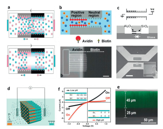
In addition to asymmetry in nanochannel geometry, surface charge in nanochannels can be modified to make the ICR occur [48, 80-93]. The idea of a nanofluidic diode consisting of opposite surface charges on either half of nanochannel was proposed by Daiguji and his co-workers [48]. The asymmetric surface charge distribution in nanochannels gives strong rectification of ion current. Fig. 5a shows the schematics of forward and reverse biasing nanofluidic diodes. Under forward bias, the counterions inside the EDL approach to the junction wall, resulting in ions accumulation near the junction. Under this circumstance, a continuous current can be achieved. Under reverse bias, the counterions inside the electrical double layers apart from the junction. The ions are depleted from the junction, and the current ceases. In another work, asymmetric surface charge distribution was achieved using diffusion-limited patterning method [80]. As shown in Fig. 5b, one half of the channel was patterned with avidin molecules, while the other half was biotin moieties. Because avidin is a highly cationic protein, a surface charge discontinuity in the nanofluidic channel could be obtained, resulting in an obvious ICR phenomenon. By connecting positively and negatively charged surfaces using distinct isoelectric points of SiO2 and Al2O3 surfaces, nanofluidic channel containing an abrupt junction was created (Fig. 5c) [81]. The method provides much more robust surface charges than surface charge modifications, and the fabricated nanofluidic diodes exhibit high rectification of ion current. In another study, the integration of functional groups modification at designed positions was first developed to achieve asymmetric surface charge distribution in nanochannel (Figs. 5d and e) [82]. Due to the protonation/deprotonation of amine at the patterned position, the charges distribution in nanochannel array is discontinuous, enable to regulate ion transport selectivity (Fig. 5f). The mechanism of ICR was studied by using finite element method. Theoretical simulations show that ion accumulation and depletion caused by discontinuous surface charge distribution are the reason responsible for ICR. Moreover, a bulletshaped nanopore can also be used to generate the ICR [83], which could be influnced by the nanopore shape, solution pH, and bulk salt concentrations.
In addition to the conventional methods for construction of asymmetric surface charge described above, nanoparticles could be assembled to various supports with varied charges for fabrication of ICR devices [87-95]. By in-situ assembly of nanoparticles in micorchannels, an nanochannel hybrid with asymmetric charges was constructed [88]. The formed nanofluidic device offers perfect ICR characteristic. In a similar mode, gold nanoparticles were self-assembled on tip of a glass nanopipette using DNA as the link reagent [94, 95]. The intergaps among gold nanoparticles are in range of nanoscale, and could be further tuned by changing pH values.
It has been demonstrated above that mass transport in nanochannels is dominated by the charge and size effect (Fig. 2a). The asymmetric surface charge distribution endows the channels with varied charge effect. In the region with high surface charge, the ions transport will be influenced by charge density more intensely. In case of EDL overlaps, the charge density is super high. Under this circumstance, it is very hard for co-ions to enter the nanochannels from the tip side. To maintain the electric neutrality of the whole nanochannels, the ions in nanochannels must be very rare, which results in ions depletion and "off" state in nanochannel. Reversing the potential direction, the co-ions can easily enter the nanochannels from the side with bigger size and less charge density. Both cations and anions will be then enriched in the nanochannels. Under this circumstance, the nanochannel is "on". Therefore, under varied potential polarity, the ICR can be observed in nanochannels with asymmetric surface charge distribution.
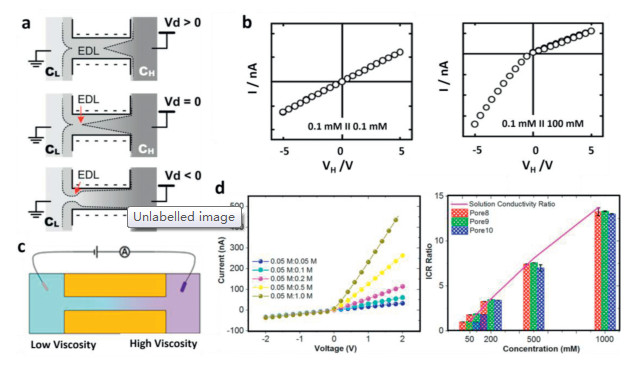
ICR can also be produced in a homogeneous symmetric nanochannel containing ion concentration gradients along the channel [96, 97]. The ion concentration gradients can be achieved by placing nanochannel between the asymmetric bath concentrations (Figs. 6a and b) [96]. The asymmetric ion conductance occurs when one side of nanochannel has overlapped EDL due to the low bath electrolyte concentration, while the other side does not. Under this circumstance, the charged channel walls provide asymmetric electrostatic impact on the ions between the two sides of nanochannel, accordingly inducing the ICR. Similarly, the viscosity gradient in nanochannel can enable the generation of the ICR (Figs. 6c and d) [97]. Through precisely controlling the different viscosities on the two sides of nanochannel, the conductivity gradient in nanochannel give rise to obvious ICR behavior.
It is known that the ionic strength influences the thickness of EDL [55]. Thus, the varied ions concentrations result in different EDL thickness. The higher the ionic strength is, the thinner the EDL is. Varied EDL results in different free transport region and electrostatic interaction region as well as the charge density in nanochannel (Fig. 2a). ICR will occur following the same principle as descried in the "asymmetric surface charge distribution" part.
Recently, Tagliazucchi and his co-workers found that the ICR could also occur in nanochannels with different outer membrane charges [98]. In their study, the two sides of the nanochannel charged oppositely. Using this nanochannel, ICR were found. They investigated the mechanism using a numerical model, and revealed that ICR is caused by the decreased electrical resistance within nanochannel as the internal salt concentration increases. Under the negative applied potential, the ions enrich, and the current increases. In comparison, the ions deplete under positive applied potential. To better understand the difference between the inner wall and outer surface of nanochannels on ICR, a device composed of inner-wall and outer surface was constructed (Fig. 7a) [99, 100]. After assembling gold layer on PAA, DNA are modified on the device via chemical coupling. The DNA frameworks have the capacity of mediating electron transfer and generate the electrochemical current at the same time. The mass transport property was then monitored under different asymmetric conditions. It was revealed that the outer surface plays critical role in the mass transport of nanochannels.
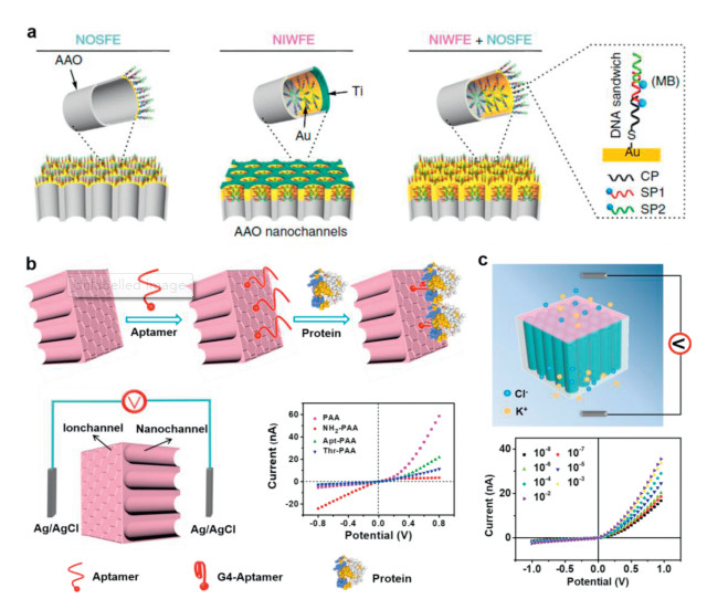
Since the probe modification and molecular recognition can be performed on the outer surface of nanochannels membrane, the sample block in nanochannels can be efficiently avoided. Therefore, the ICR devices making use of the asymmetric outer surface charges offer a new platform and strategy in various application fields, which ensures the sensitivity, repeatability and accuracy of the experiment results [6, 69, 78, 99-110]. Based on the asymmetric outer surface charges of PAA, a series of studies on biomolecular recognition events were successfully performed [69, 78, 101-104, 106, 100-110]. In a recent work, the aptamer probe was immobilized on the outer side of PAA. The probed-modified PAA have the capacity of recognizing the target protein. After incubating with the biological sample, the special protein could be enriched. Based on the changed ICR properties of the nanofluidic device before and after molecular recognition, the protein concentration and the biological reaction kinetics could be accurately detected (Fig. 7b) [104]. Using the same molecular recognition principle, the cell surface glycans were successfully detected presently using a label-free and real-time way (Fig. 7c) [109]. Results show that the present strategy for glycan detection can achieve a detection limit of ~10 amol/L, which is substantially lower than most previous works. In addition to the biomolecular recognition, the cells can be sensitively captured and detected using this method. Using PAA nanochannels membrane, Wang et al. constructed a nanofluidic platform integrating electrochemical detector for efficient enrich and sensitive detection of circulating tumor cells (CTCs) [101, 110]. Results showed that the present strategy could achieve the detection limit of about 100 cells/mL. The present method provides a simple, sensitive, and label-free technique for bioanalysis, which would hold great potential in the early clinical diagnosis and treatment of cancers.
The above studies reveal the critical role of the outer surface in the generation and applications of ICR. The ICR in asymmetric outer surface charges can be explained using the principle of ions accumulation and depletion demonstrated in Fig. 3c. When a positive voltage is applied, cations migrate from top to bottom, and the moving direction of anions is opposite. Owing to electrostatic interaction, ion accumulating occurs in PAA, resulting in a high ionic current and "on" state current. On the contrary, when the potential is negatively applied, anions will be excluded away from PAA. To maintain the electrically neutral in PAA, cations passing through PAA must be limited. Accordingly, the ion concentration in PAA is depleted, and the current is "off" state. Therefore, under varied potential polarity, nanofluidic devices with asymmetric outer surface charge present distinct ICR property.
We have provided an overview of the concept of ICR in asymmetric nanofluidic devices. The fundamental of mass transfer and ICR behaviors in nanofluidics are clearly explained, and the generation mechanism of ICR is deeply demonstrated. The factors determining the ICR property are highlighted in detail, which include asymmetry geometry, charge distribution along the channel and on the outer sides of channel, bath concentrations, or a combination of these aspects. Up to now, ICR devices have been widely used in various fields. It has been demonstrated that the unique ICR property can be used in bioanalysis/sensors with high sensitivity and accuracy including biomolecular recognition, small molecules/ions detection, and cell capture/detection. It is obvious that design and fabrication of new ICR devices provides new strategies for pushing forward nanofluidics in various fields such as bioanalysis, energy conversion, gas separation.
Despite obvious improvements have been made in this attractive field, there are still some challenges facing researchers. For example, the space confinement and surface charge effect of nanofludic devices make their applications in the analysis of single molecule, single cell and single particle highly anticipated. But how does the surface chemistry and geometry control over the asymmetric and reversible ionic switching? In addition, it is expected that the dynamic nanochannel may trigger further interests in the study of dynamic nanomaterials for exploring smart nanochannel systems. However, to date, most artificial nanochannels are prepared by the static approaches, and the ICR research toward dynamic nanochannels is still in its early stages. With the discovery of novel phenomena, new theories and intriguing liquid behaviors will be revealed. Comprehensive understanding of mass transport properties at the nanoscale would be the key to break through the potential application of nanofludics in various fields. We hope that the nanofluidic devices and the ICR property will find more applications in varied fields in the future.
The authors declare that they have no known competing financial interests or personal relationships that could have appeared to influence the work reported in this paper.
This work was supported by the National Natural Science Foundation of China (Nos. 21874155, 21575163), the Natural Science Foundation of Jiangsu Province (No. BK20191316), the Double First-Class University Project (No. CPU2018GY25), the State Key Laboratory of Analytical Chemistry for Life Science (No. SKLACLS1919), and the Qing-Lan Project of Jiangsu Province (2019). We sincerely thank Prof. Xing-Hua Xia in Nanjing University for the kind instructions and discussions.
G.M. Whitesides, Nature 442 (2006) 368-373. doi: 10.1038/nature05058
C. Wang, J. Ouyang, H.L. Gao, et al., Talanta 85 (2011) 298-303. doi: 10.1016/j.talanta.2011.03.057
M.S. Jie, S.F. Mao, H.F. Li, J.M. Lin, Chin. Chem. Lett. 28 (2017) 1625-1630. doi: 10.1016/j.cclet.2017.05.024
H.C. Wang, T.J. Li, Y.R. Bao, S. Wang, X.S. Meng, Chin. Chem. Lett. 30 (2019) 403-405. doi: 10.1016/j.cclet.2018.08.016
T.Y. Yuan, D. Gao, S.F. Li, Y.Y. Jiang, Chin. Chem. Lett. 30 (2019) 331-336. doi: 10.1016/j.cclet.2018.07.013
W.Q. Yue, Z. Tan, X.P. Li, F.F. Liu, C. Wang, Trends Anal. Chem. 117 (2019) 101-115. doi: 10.1016/j.trac.2019.06.009
J.C. Eijkel, A. Van Den Berg, Microfluid Nanofluid 1 (2005) 249-267. doi: 10.1007/s10404-004-0012-9
P. Abgrall, N.T. Nguyen, Anal. Chem. 80 (2008) 2326-2341. doi: 10.1021/ac702296u
C. Wang, S.J. Li, Z.Q. Wu, et al., Lab Chip 10 (2010) 639-646. doi: 10.1039/B915762J
C. Wang, J. Ouyang, D.K. Ye, et al., Lab Chip 12 (2012) 2664-2671. doi: 10.1039/c2lc20977b
C. Wang, J.J. Xu, H.Y. Chen, X.H. Xia, Sci. China:Chem. 55 (2012) 453-468. doi: 10.1007/s11426-012-4542-9
C. Wang, Z.H. Sheng, J. Ouyang, et al., ChemPhysChem 13 (2012) 762-768. doi: 10.1002/cphc.201100842
C. Wang, D.K. Ye, Y.Y. Wang, T. Lu, X.H. Xia, Lab Chip 13 (2013) 1546-1553. doi: 10.1039/c3lc41319e
C. Wang, J. Ouyang, Y.Y. Wang, D.K. Ye, X.H. Xia, Anal. Chem. 86 (2014) 3216-3221. doi: 10.1021/ac500196s
L.X. Zhang, Y.B. Zheng, S.L. Cai, X.H. Cao, Y.Q. Li, Chin. Chem. Lett. 26 (2015) 43-46. doi: 10.1016/j.cclet.2014.08.001
W.J. Lan, M.A. Edwards, L. Luo, et al., Acc. Chem. Res. 49 (2016) 2605-2613. doi: 10.1021/acs.accounts.6b00395
R.R. Li, X. Fan, Z.Y. Liu, J. Zhai, Adv. Mater. 29 (2017) 1702983. doi: 10.1002/adma.201702983
Y.P. Feng, L.P. Ding, D.Y. Ji, L.L. Wang, W. Guo, Chin. Chem. Lett. 29 (2018) 892-894. doi: 10.1016/j.cclet.2018.01.053
H.C. Yang, Y. Xie, J. Hou, et al., Adv. Mater. 30 (2018) e1801495. doi: 10.1002/adma.201801495
L.P. Wen, X.Q. Zhang, Y. Tian, L. Jiang, Sci. China Mater. 61 (2018) 1027-1032. doi: 10.1007/s40843-018-9289-2
Q. Zhang, Y. Cheng, P.S. Cao, Z.Y. Gu, Chin. Chem. Lett. 30 (2019) 1607-1617. doi: 10.1016/j.cclet.2019.06.011
Z.P. Zhu, D.Y. Wang, Y. Tian, L. Jiang, J. Am. Chem. Soc. 141 (2019) 8658-8669. doi: 10.1021/jacs.9b00086
M.T. Deng, M. Yang, Y.Q. Xu, et al., Chin. Chem. Lett. 30 (2019) 1397-1400. doi: 10.1016/j.cclet.2019.04.003
Z. Zhang, X.D. Huang, Y.C. Qian, et al., Adv. Mater. 32 (2020) e1904351. doi: 10.1002/adma.201904351
C. Wei, A.J. Bard, S.W. Feldberg, Anal. Chem. 69 (1997) 4627-4633. doi: 10.1021/ac970551g
I. Vlassiouk, T.R. Kozel, Z.S. Siwy, J. Am. Chem. Soc. 131 (2009) 8211-8220. doi: 10.1021/ja901120f
B. Yameen, M. Ali, R. Neumann, et al., J. Am. Chem. Soc.131 (2009) 2070-2071. doi: 10.1021/ja8086104
M. Ali, Q.H. Nguyen, R. Neumann, W. Ensinger, Chem. Commun. 46 (2010) 6690-6692. doi: 10.1039/c0cc01632b
M. Ali, B. Yameen, J. Cervera, et al., J. Am. Chem. Soc. 132 (2010) 8338-8348. doi: 10.1021/ja101014y
X.L. He, K.L. Zhang, T. Li, et al., J. Am. Chem. Soc. 139 (2017) 1396-1399. doi: 10.1021/jacs.6b11696
X. Hou, H. Dong, D.B. Zhu, L. Jiang, Small 6 (2010) 361-365. doi: 10.1002/smll.200901701
Z. Siwy, A. Fulinski, Phys. Rev. Lett. 89 (2002) 198103. doi: 10.1016/j.nimb.2005.03.265
C.Y. Lin, L.H. Yeh, Z.S. Siwy, J. Phys. Chem. Lett. 9 (2018) 393-398. doi: 10.1021/acs.jpclett.7b03099
C.Y. Lin, C. Combs, Y.S. Su, L.H. Yeh, Z.S. Siwy, J. Am. Chem. Soc. 141 (2019) 3691-3698. doi: 10.1021/jacs.8b13497
X.L. He, K.L. Zhang, Y. Liu, et al., Angew. Chem. Int. Ed. 57 (2018) 4590-4593. doi: 10.1002/anie.201800335
X.D. Huang, X.Y. Kong, L.P. Wen, L. Jiang, Adv. Funct. Mater. 28 (2018) 1801079. doi: 10.1002/adfm.201801079
Y.H. Qiu, Z.S. Siwy, M. Wanunu, Anal. Chem. 91 (2019) 996-1004. doi: 10.1021/acs.analchem.8b04225
S.J. Kim, Y.A. Song, J. Han, Chem. Soc. Rev. 39 (2010) 912-922. doi: 10.1039/b822556g
L.J. Cheng, L.J. Guo, Chem. Soc. Rev. 39 (2010) 923-938. doi: 10.1039/B822554K
A. Piruska, M.J. Gong, J.V. Sweedler, P.W. Bohn, Chem. Soc. Rev. 39 (2010) 1060-1072. doi: 10.1039/B900409M
T.A. Zangle, A. Mani, J.G. Santiago, Chem. Soc. Rev. 39 (2010) 1014-1035. doi: 10.1039/b902074h
W. Guo, Y. Tian, L. Jiang, Acc. Chem. Res. 46 (2013) 2834-2846. doi: 10.1021/ar400024p
J. Gao, Y.P. Feng, W. Guo, L. Jiang, Chem. Soc. Rev. 46 (2017) 5400-5424. doi: 10.1039/C7CS00369B
Y. Xu, M. Shinomiya, A. Harada, Adv. Funct. Mater. 28 (2016) 2209-2216. doi: 10.1002/adma.201505132
Y. Xu, Adv. Mater. 30 (2018) 1702419. doi: 10.1002/adma.201702419
H.C. Zhang, Y. Tian, L. Jiang, Nano Today 11 (2016) 61-81. doi: 10.1016/j.nantod.2015.11.001
J. Cervera, B. Schiedt, R. Neumann, S. Mafé, P. Ramírez, J. Chem. Phys. 124 (2006) 104706. doi: 10.1063/1.2179797
H. Daiguji, Y. Oka, K. Shirono, Nano Lett. 5 (2005) 2274-2280. doi: 10.1021/nl051646y
H. Daiguji, Chem. Soc. Rev. 39 (2010) 901-911. doi: 10.1039/B820556F
X. Hou, W. Guo, L. Jiang, Chem. Soc. Rev. 40 (2011) 2385-2401. doi: 10.1039/c0cs00053a
Z. Zhang, L.P. Wen, L. Jiang, Chem. Soc. Rev. 47 (2018) 322-356. doi: 10.1039/C7CS00688H
Y. Sun, J.K. Ma, F. Zhang, et al., Nat. Commun. 8 (2017) 260. doi: 10.1038/s41467-017-00330-z
Y. Sun, F. Zhang, J.X. Quan, et al., Nat. Commun. 9 (2018) 2617. doi: 10.1038/s41467-018-05103-w
R. Wang, Y. Sun, F. Zhang, et al., Angew. Chem. Int. Ed. 56 (2017) 5294-5298. doi: 10.1002/anie.201702175
W. Chen, Z.Q. Wu, X.H. Xia, J.J. Xu, H.Y. Chen, Angew. Chem. Int. Ed. 49 (2010) 7943-7947. doi: 10.1002/anie.201002711
S.J. Li, J. Li, K. Wang, et al., ACS Nano 4 (2010) 6417-6424. doi: 10.1021/nn101050r
J. Yu, L. Zhang, X. Xu, S. Liu, Anal. Chem. 86 (2014) 10741-10748. doi: 10.1021/ac502752g
J.C. Yu, P.C. Luo, C.X. Xin, et al., Anal. Chem. 86 (2014) 8129-8135. doi: 10.1021/ac501135u
H.L. Gao, M. Wang, Z.Q. Wu, et al., Anal. Chem. 87 (2015) 3936-3941. doi: 10.1021/ac504830e
C. Wang, H.L. Liu, Y.Q. Li, et al., Electrochem. Commun. 66 (2016) 25-28. doi: 10.1016/j.elecom.2016.02.016
X.P. Zhao, J. Cao, X.G. Nie, et al., Electrochem. Commun. 81 (2017) 5-9. doi: 10.1016/j.elecom.2017.05.018
C.Y. Li, Y.W. Tian, W.T. Shao, et al., Electrochem. Commun. 42 (2014) 1-5. doi: 10.1016/j.elecom.2014.01.020
R.T. Perera, R.P. Johnson, M.A. Edwards, H.S. White, J. Phys. Chem. C 119 (2015) 24299-24306. doi: 10.1021/acs.jpcc.5b08194
D.F. Ding, P.C. Gao, Q. Ma, D.G. Wang, F. Xia, Small 15 (2019) e1804878. doi: 10.1002/smll.201804878
P. Ramírez, P.Y. Apel, J. Cervera, S. Mafé, Nanotechnology 19 (2008) 315707. doi: 10.1088/0957-4484/19/31/315707
M.L. Kovarik, K. Zhou, S.C. Jacobson, J. Phys. Chem. B 113 (2009) 15960-15966. doi: 10.1021/jp9076189
D. Woermann, Phys. Chem. Chem. Phys. 5 (2003) 1853-1858. doi: 10.1039/b301021j
H.S. White, A. Bund, Langmuir 24 (2008) 2212-2218. doi: 10.1021/la702955k
F.F. Liu, Y.C. Guo, W. Wang, Y.M. Chen, C. Wang, Nanoscale (2020), doi:http://dx.doi.org/ 10.1039/D0NR01054E.
Y.N. Jiang, Y.P. Feng, J.J. Su, et al., J. Am. Chem. Soc. 139 (2017) 18739-18746. doi: 10.1021/jacs.7b11732
T. James, Y.V. Kalinin, C.C. Chan, et al., Nano Lett. 12 (2012) 3437-3442. doi: 10.1021/nl300673r
Jl. Li, D. Stein, C. McMullan, et al., Nature 412 (2001) 166-169. doi: 10.1038/35084037
C.Y. Li, Z.Q.Wu, C.G. Yuan, K.Wang, X.H. Xia, Anal.Chem.87 (2015) 8194-8202. doi: 10.1021/acs.analchem.5b01016
C.Y. Li, Y. Zhao, L. He, et al., Chem. Commun. 54 (2018) 3122-3125. doi: 10.1039/C8CC00209F
J.M. Perry, K. Zhou, Z.D. Harms, S.C. Jacobson, ACS Nano 4 (2010) 3897-3902. doi: 10.1021/nn100692z
Z. Siwy, Y. Gu, H.A. Spohr, et al., Europhys. Lett. 60 (2002) 349-355. doi: 10.1209/epl/i2002-00271-3
Z. Siwy, E. Heins, C.C. Harrell, P. Kohli, C.R. Martin, J. Am. Chem. Soc. 126 (2004) 10850-10851. doi: 10.1021/ja047675c
C. Wang, F.F. Liu, Z. Tan, et al., Adv. Funct. Mater. 30 (2020) 1908804. doi: 10.1002/adfm.201908804
Z.Y. Jiang, H.L. Liu, S.A. Ahmed, et al., Angew. Chem. Int. Ed.129 (2017) 4845-4849. doi: 10.1002/ange.201701279
R. Karnik, C.H. Duan, K. Castelino, H. Daiguji, A. Majumdar, NanoLett. 7 (2007) 547-551. doi: 10.1021/nl062806o
L.J. Cheng, L.J. Guo, ACS Nano 3 (2009) 575-584. doi: 10.1021/nn8007542
C.Y. Li, F.X. Ma, Z.Q. Wu, et al., Adv. Funct. Mater. 23 (2013) 3836-3844. doi: 10.1002/adfm.201300315
J.P. Hsu, H.H. Wu, C.Y. Lin, S. Tseng, Anal. Chem. 89 (2017) 3952-3958. doi: 10.1021/acs.analchem.6b04325
R. Karnik, K. Castelino, C.H. Duan, A. Majumdar, Nano Lett. 6 (2006) 1735-1740. doi: 10.1021/nl061159y
I. Vlassiouk, Z.S. Siwy, Nano Lett. 7 (2007) 552-556. doi: 10.1021/nl062924b
H. Miedema, M. Vrouenraets, J. Wierenga, et al., Nano Lett. 7 (2007) 2886-2891. doi: 10.1021/nl0716808
Y.H. Lei, W. Wang, W.G. Wu, Z.H. Li, Appl. Phys. Lett. 96 (2010) 263102. doi: 10.1063/1.3456563
E. Choi, C. Wang, G.T. Chang, J. Park, Nano Lett. 16 (2016) 2189-2197. doi: 10.1021/acs.nanolett.5b04246
J.M. Sang, H.T. Du, W. Wang, et al., Biomicrofluidics 7 (2013) 024112. doi: 10.1063/1.4802936
L.B. Shao, M.X. Zheng, W. Wang, Appl. Phys. Lett. 106 (2015) 093105. doi: 10.1063/1.4913971
W. Ouyang, J. Han, W. Wang, Lab Chip 17 (2017) 3006-3025. doi: 10.1039/C7LC00588A
W. Ouyang, W. Wang, H.X. Zhang, W.G. Wu, Z.H. Li, Nanotechnology 24 (2013) 345401. doi: 10.1088/0957-4484/24/34/345401
Y.H. Lei, F. Xie, W. Wang, W.G. Wu, Z.H. Li, Lab Chip 10 (2010) 2338-2340. doi: 10.1039/c004758a
H.L. Liu, Q.C. Jiang, J. Pang, et al., Adv. Funct. Mater. 28 (2018) 1703847. doi: 10.1002/adfm.201703847
H.L. Liu, J. Cao, S. Hanif, et al., Anal. Chem. 89 (2017) 10407-10413. doi: 10.1021/acs.analchem.7b02410
L.J. Cheng, L.J. Guo, Nano Lett. 7 (2007) 3165-3171. doi: 10.1021/nl071770c
Y.H. Qiu, R.A. Lucas, Z.S. Siwy, J. Phys. Chem. Lett. 8 (2017) 3846-3852. doi: 10.1021/acs.jpclett.7b01804
M. Tagliazucchi, Y. Rabin, I. Szleifer, ACS Nano 7 (2013) 9085-9097. doi: 10.1021/nn403686s
P.C. Gao, Q. Ma, D.F. Ding, et al., Nat. Commun. 9 (2018) 4557. doi: 10.1038/s41467-018-06873-z
X.C. Li, T.Y. Zhai, P.C. Gao, H.L. Cheng, F. Xia, Nat. Commun. 9 (2018) 40. doi: 10.1038/s41467-017-02447-7
J. Cao, X.P. Zhao, M.R. Younis, et al., Anal. Chem. 89 (2017) 10957-10964. doi: 10.1021/acs.analchem.7b02765
X.P. Zhao, S.S. Wang, M.R. Younis, X.H. Xia, C. Wang, Adv. Mater. Interfaces 5 (2018)1800185. doi: 10.1002/admi.201800185
X.P. Zhao, S.S. Wang, M.R. Younis, X.H. Xia, C. Wang, Anal. Chem. 90 (2018) 896-902. doi: 10.1021/acs.analchem.7b03818
X.P. Zhao, Y. Zhou, Q.W. Zhang, et al., Anal. Chem. 91 (2019) 1185-1193. doi: 10.1021/acs.analchem.8b05162
L. Shi, C.L. Mu, T. Gao, et al., J. Am. Chem. Soc. 141 (2019) 8239-8243.
C. Wang, Y. Wang, Y. Zhou, Z.Q. Wu, X.H. Xia, Anal. Bioanal. Chem. 411 (2019) 4007-4016. doi: 10.1007/s00216-019-01756-8
X.P. Zhao, F.F. Liu, W.C. Hu, et al., Anal. Chem. 91 (2019) 3582-3589. doi: 10.1021/acs.analchem.8b05536
F.F. Liu, X.P. Zhao, B. Kang, X.H. Xia, C. Wang, Trends Anal. Chem. 123 (2020) 115760. doi: 10.1016/j.trac.2019.115760
F.F. Liu, X.P. Zhao, X.W. Liao, et al., Anal. Chem. 92 (2020) 5509-5516. doi: 10.1021/acs.analchem.0c00330
C. Wang, X.P. Zhao, F.F. Liu, et al., Nano Lett. 20 (2020) 1846-1854. doi: 10.1021/acs.nanolett.9b05066

Figure 2 (a) Illustration of mass transfer in nanochannels with different dimensions. Top: The diameter is much larger than the size of all molecules; Middle: the diameter is larger than the size of small molecules but smaller than that of macromolecules; Bottom: the diameter is small enough for the EDL overlap completely. Reproduced with permission [11]. Copyright 2012, Elsevier. (b) Schematic illustration of the DNA detection principle using array nanochannels coupled with electrochemical detector. Reproduced with permission [56]. Copyright 2010, American Chemical Society. (c) Functionalization of nanochannels with DNA and the electrochemical response in the absence and presence of antidigoxin. Reproduced with permission [58]. Copyright 2014, American Chemical Society. (d) Schematic illustration of pH-regulated ionic transport in nanochannels. Reproduced with permission [62]. Copyright 2014, Elsevier. (e) Experimental design and results or measuring the temperature dependent I-V curves in conical nanopores. Reproduced with permission [63]. Copyright 2015, American Chemical Society.

Figure 3 (a) Left: Schematic axial cut through a nanochannel. Right: The force (solid line) and the corresponding potential (dashed line) acting on a unitary positive charge at the position z on the axis of the conical channel. Reproduced with permission [32]. Copyright 2002, American Physical Society. (b) Left: Schematic showing the cross section of a conical nanopore with negative surface charge. Potentials are applied to the working electrode relative to the counter electrode. Right: I-V curves for the 10, 35 and 85 nm pores filled with 10 mmol/L phosphate buffer with 0.1 mol/L KCl. Reproduced with permission [66]. Copyright 2009, American Chemical Society. (c) Illustration of the ICR mechanism. The "off" state results from remarkable ion depletion in nanochannels; The "on" state comes from efficient ion concentration enrichment in the nanochannel. Reproduced with permission [69]. Copyright 2020, Royal Society of Chemistry.

Figure 4 (a) Illustration of ICR in a conical nanopore. The arrows illustrate the motion of cations and relative magnitude of ionic current in the corresponding electrode configurations. (b) I-V curves measured in 20 and 100 mmol/L KCl at pH 7 and I-V curves measured in 20 mmol/L KCl at pH 2 and pH 8. Reproduced with permission [71]. Copyright 2012, American Chemical Society. (c) Illustration of ICR in branching nanochannel array. (d) Experimental ionic rectification characteristics of PAA membranes consisting of different geometry nanochannels measured in 1 mmol/L KCl with different pH values. Reproduced with permission [73]. Copyright 2015, American Chemical Society. (e) Schematical illustration of the self-made electrochemical device for I-V measurement. (f) I-V curves of the hybrid in 1 mmol/L KCl solution (pH 7) and the mechanism for "on" state in ICR, which comes from ion concentration enrichment in the nanochannels. Reproduced with permission [78]. Copyright 2020, Wiley-VCH.

Figure 5 (a) Schematic diagram of forward (top one) and reverse (bottom one) biasing nanofluidic diodes. Reproduced with permission [48]. Copyright 2005, American Chemical Society. (b) Schematic layout of a nanofluidic diode consisting of avidin patterned in half the channel, and epifluorescence image of the fabricated nanofluidic diode. Scale bar: 20 μm. Reproduced with permission [80]. Copyright 2007, American Chemical Society. (c) Microscope image andschematic illustration of a heterogeneous nanochannel consisting of two different oxide surfaces. Reproduced with permission [81]. Copyright 2009, American Chemical Society. (d) Schematic illustration of rectification characterization for PAA membrane patterned with APTMS. (e) Cross-sectional laser scanning confocal microscopy image of the PAA membrane with precise modification. (f) Experimental ICR characteristic of fabricated PAA membranes. Reproduced with permission [82]. Copyright 2013, Wiley-VCH.

Figure 6 (a) Schematic illustration of the rectifying effect due to the disparate ion distribution along the nanochannel under different polarities of applied potential. Top: High concentration side is positively biased relative to the low concentration side; Middle: zero bias; Bottom: negatively bias. The gray region within the nanochannel that is bound by the dashed lines represents the electric double layers (EDL). (b) Measured I-V characteristics of nanochannels under various asymmetric concentrations. Reproduced with permission [96]. Copyright 2007, American Chemical Society. (c) The experimental setup performed in a two-electrode system. (d) Left: current-voltage curves of a pore placed in contact with concentration gradients of KCl, as noted in the Figure. Right: rectification degrees calculated at 2 V for three pores placed in contact with KCl concentration gradients. Reproduced with permission [97]. Copyright 2017, American Chemical Society.

Figure 7 (a) Presentation of DNA assembling at different regions of metal decorated nanochannels. Reproduced with permission [100]. Copyright 2018, Nature Publishing Group. (b) Illustration of the biomolecular recognition detection principle. Reproduced with permission [104]. Copyright 2019, American Chemical Society. (c) Schematic illustration of the electrochemical device for I-V measurement and the I-V curves of con A modified nanochannels after incubation with different concentrations of glycan. Reproduced with permission [109]. Copyright 2020, American Chemical Society.

 扫一扫看文章

扫一扫关注我们
 DownLoad:


 下载:
下载: