Citation:
Liu Yanbiao, Liu Fuqiang, Ding Ning, Hu Xuemei, Shen Chensi, Li Fang, Huang Manhong, Wang Zhiwei, Sand Wolfgang, Wang Chong-Chen. Recent advances on electroactive CNT-based membranes for environmental applications: The perfect match of electrochemistry and membrane separation[J]. Chinese Chemical Letters,
2020, 31(10): 2539-2548.
doi:
10.1016/j.cclet.2020.03.011
Recent advances on electroactive CNT-based membranes for environmental applications: The perfect match of electrochemistry and membrane separation
English
Recent advances on electroactive CNT-based membranes for environmental applications: The perfect match of electrochemistry and membrane separation
Textile Pollution Controlling Engineering Center of Ministry of Environmental Protection, College of Environmental Science and Engineering, Donghua University, Shanghai 201620, China
b.
Shanghai Institute of Pollution Control and Ecological Security, Shanghai 200092, China
c.
Key Laboratory of Cleaner Production and Integrated Resource Utilization of China National Light Industry, Beijing Technology and Business University, Beijing 100048, China
d.
State Key Laboratory of Pollution Control and Resource Reuse, School of Environmental Science and Engineering, Tongji University, Shanghai 200092, China
e.
Institute of Biosciences, Freiberg University of Mining and Technology, Freiberg 09599, Germany
f.
Beijing Key Laboratory of Functional Materials for Building Structure and Environment Remediation, Beijing University of Civil Engineering and Architecture, Beijing 100044, China
* Corresponding author at: Textile Pollution Controlling Engineering Center of Ministry of Environmental Protection
Received Date:
03 January 2020 Accepted Date:
04 March 2020 Revised Date:
27 February 2020 Available Online:
15 October 2020
Abstract:
Global climate change, growing population, and environmental pollution underscore the need for a greater focus on providing advanced water treatment technologies. Although electrochemical based-processes are becoming promising solutions, they still face challenges owing to mass transport and upscaling which hinder the exploitation of this technology. Electrode design and reactor configuration are key factors for achieving operational improvements. The electroactive membrane has proven to be a breakthrough technology integrating electrochemistry and membrane separation with an enhanced mass transport by convection. In this review article, we discuss recent progress in environmental applications of electroactive membranes with particular focus on those composed of carbon nanotubes (CNT) due to their intriguing physicochemical properties. Their applications in degradation of refractory contaminants, detoxification and sequestration of toxic heavy metal ions, and membrane fouling alleviations are systematically reviewed. We then discuss the existing limitations and opportunities for future research. The development of advanced electroactive systems depends on interdisciplinary collaborations in the areas of materials, electrochemistry, membrane development, and environmental sciences.
Increasing water scarcity is one of the leading challenges for sustainable development. The situation may become even worse with an increasing global population, global climate changes, and rapid industrialization. Furthermore, conventional water treatments are not designed to remove the existing diversity of emerging contaminants. The membrane based processes like microfiltration (MF), ultrafiltration (UF), nanofiltration (NF), reverse osmosis (RO), forward osmosis (FO), membrane bioreactor (MBR), and membrane distillation (MD) were generally recognized as viable technologies and promising strategies for the treatment and reclamation of water [1-4]. The attributes of this technology includes high selectivity, easy automation, scale-up, modular design, low space requirement, and limited energy consumption, thus outperforming several traditional physicochemical approaches [5, 6]. Till now, combined membrane based-processes such as UF-RO have expanded for industrial wastewater treatment or seawater desalination applications [7-9].
Although these conventional membranes are widely used, some challenges still need to be addressed [10]. Firstly, besides servicing as a separating media, membrane technology may be suitable for other applications (e.g., electrode materials) by delicate design of the filtration system [11]. Secondly, the membrane fouling issue has not yet been addressed sufficiently [12-14]. Several strategies have been attempted to recover membrane performance (e.g., pre-treatment of raw water, optimization of operation conditions, and membrane cleaning), but only with limited success [15, 16]. Thirdly, these most widely used lowpressure membrane technologies, e.g., MF and UF, are usually ineffective in rejecting dissolved organic pollutants of low molecular weight (MW) and other emerging contaminants (e.g., antibiotics). Although RO and NF have been developed to remove dissolved salts, these processes only show limited success in the rejection of small organic molecules (MW < 100 Da) such as phenolic compounds. In addition, these processes usually require high transmembrane pressure and management of the concentrate, greatly increasing the overall operating cost [17]. Accordingly, further progress is necessary for the development of membrane technology with improved antifouling properties and multifunctionality.
The development of the electroactive membrane as the nextgeneration membrane technology attracts increasing attentions from the scientific community [18-21]. This promising technology perfectly combines electrochemistry with a membrane separation process. To date, several smart designs have been proposed based on various organic and inorganic materials [22-24]. These designs enable conduction and distribution of an external electric potential across the entire or part of the membrane surface. This brings many interesting phenomena at the membrane/water interface: (I) Enables physical adsorption and chemical oxidation of pollutants on site, which may alleviate the membrane fouling [25, 26], (Ⅱ) promotes the mass transport of ionic compounds by electromigration [27], and (Ⅲ) increases the electrostatic repulsive forces towards like-charged foulants [28-30]. Thus, this technology can be useful for point-of-use applications as either a standalone unit or a further polishing step [31].
The rapid development of this field is also reflected by the increase of publications over the years and the publication of a number of comprehensive reviews on this topic [22, 32, 33]. However, to the best of our knowledge, there is no scientific review available on the recent advances on the electroactive carbon nanotubes (CNT) membranes. The objective of this work is to provide a state-of-the-art on the electroactive CNT-based membranes and their environmental applications with particular focus on the degradation of refractory contaminants, detoxification and sequestration of toxic heavy metal ions, and alleviation of membrane fouling. The technological limitations and future perspectives of this technology for its application in water treatment were analyzed as well.
2.
Why carbon nanotubes?
Electroactive membranes can be fabricated using various organic and inorganic materials, including polymers, sub-stoichiometric TiO2, and conductive carbons [25, 34, 35]. The performance of an electroactive membrane is closely related to the microstructure and physicochemical properties of the materials. Further, other factors such as module design, mechanical strength, electrical conductivity, and fabrication protocols of membrane materials impact on the overall performance as well.
2.1
Structural features of CNT membranes
CNT, seamless cylinders of one or more layers of graphene, possess exceptional properties of mechanical strength, electrical conductivity, high specific surface area, and thermal stability [36-38]. CNT with a perfect crystalline structure has all carbons bonded in a hexagonal lattice except at their ends, whereas structural defects introduce pentagons, heptagons, and other imperfections in the sidewalls that generally less the desired physicochemical properties [39]. Compared with the widely used polymeric membranes (e.g., polyvinyl alcohol and cellulose acetate) [40, 41], the CNT-based membranes were emerged as a new generation of membrane materials by combining electrochemistry with conventional membrane processes. Till now, two kinds of CNT membranes were developed [42]. One is based on disordered CNT powders, where CNT were arranged in a disordered manner or mixed into the polymeric network to form a dense layer [43]. The gap between CNT can be served as channels for fluid transport. The other type is well-ordered CNT array membranes, where the CNT were vertically assembled and the tube gaps were filled with polymer or ceramic matrix materials [44]. The internal pores of CNT form fluid channels. Based on several experimental investigations and theoretical calculations, the precise and tunable pore dimensions of CNT membrane greatly improve the transport kinetics and reduce the friction while fluid passing through. Furthermore, the large surface area and high mesoporous volume of CNT membranes is satisfactory for practical applications, and can be further enhanced by chemical modifications due to the rich surface chemistry of pristine CNT [39, 45]. Moreover, the interfacial interactions between organic molecules with CNT membrane mainly occurs at two regions of the CNT surfaces, at groves present at the boundary of nanotube bundles or at the external surface of the outermost CNT [46]. All these desirable characteristics make CNT membrane a promising choice for addressing the existing problems of conventional membrane processes [47].
2.2
Functional features of CNT membranes
Recently, the use of CNT has been extensively studied for energy conversion [48], medical devices [49] and water treatment [50]. CNT-based sensors have been proven to be effective for the detection of toxic compounds and gases due to their high electrochemical reactivity (104-106 S/m) [51]. In addition, the CNT have better electrocatalytic properties for many electrochemical reactions. For example, the CNT-modified glassy carbon electrode (CNT-GCE) exhibits better performance in comparison to traditional GCE, i.e., a higher peak current, a lower detection limit (1.8 × 10⁻⁹ mol/L), excellent stability and selectivity towards the detection of antiviral drugs such as valacyclovir [52]. These advantages can be attributed to the unique electronic structure, the smaller channel size, as well as the topological defects present on the tubular surface. Meanwhile, the adsorption-dependent reactivity is of importance to CNT as they have a large specific surface area (SSA, 30-500 m2/g) and have been shown to adsorb many chemical species via a combination of hydrophobic interactions and π-π interactions [53]. The one-dimensional (1D) nanotubular structure can also be easily transformed into 3D networks with a high porosity by a simple a vacuum filtration route, which favors rapid sorption kinetics in a flow-through mode for the adsorptive removal of contaminants. In 2011, Vecitis et al. proposed a smart design by combining electrochemistry with the CNT membrane, which brings the "sorption-only" concept one step further by not only physical adsorption but also electrochemical oxidation of the contaminants deposited on site [54]. The unique porous structure of CNT confers limited resistance to liquid when flowing through the pores with size at the nano/micro-scale. The forced convective CNT-based membrane is a promising water treatment flow enhances the mass transport of target molecules towards the surface active sites for adsorption and electrooxidation. This process combines separation and oxidation functions into one single unit and allows for in situ degradation of refractory pollutants without producing a concentrate that requires additional treatment. Upon application of a proper electric field, the electroactive CNT membranes are capable of degrading organic pollutants or deactivating bacteria via direct electron transfer or indirectly inducing the production of highly reactive radicals (e.g., HO· and SO4·-). For example, Li et al. developed an electroactive FO membrane not only maintains superior salt rejection efficiency (>99%), but also substantially boost the phenol (MW =94 Da) rejection efficiency from 45% at 0 V to 92% at 2.5 V [55]. Similarly, Liu et al. also realized a >90% phenol oxidation efficiency just by a single-pass through a 3D self-support electrochemical grapheneCNT hybrid membrane when assisted by a limited DC voltage [56]. When dealing with emerging contaminant, the electroactive membranes also demonstrated decent performance. Liu et al. reported a 95% degradation efficiency of antibiotic tetracycline using an electrochemical CNT filter. They found that these tetracycline molecules were not only effectively degraded after passing through the filter, but also their antimicrobial activity was significantly decreased as well [57]. However, one drawback for this process is that the tetracycline molecules were not mineralized but only present in the form of intermediates of low MW, which requires further treatment.
Many studies suggest that CNT are one of the most promising and feasible materials to fabricate electroactive membranes due to their properties [58, 59]. Particularly, the efficacy of CNT can be improved by tailoring charity, wall numbers and surface properties (for instance, incorporating polymers, metal oxide nanoparticles, or other functional nanomaterials) [60, 61]. The performance of CNT-based electroactive membranes can be further boosted by fine-tuning of the porous structures, density, or by the synthesis of aligned CNT arrays. A great deal of progress has been made in the use of CNT since the pioneering work of Vecitis et al. [62] (Fig. 1). In addition, CNT-based electroactive membranes have been demonstrated to mitigate multiple forms of fouling by combining electrochemistry [63, 64]. The effectiveness of water flux recovery has been confirmed through the application of cathodic potentials onto the CNT-based membranes. The in situ produced hydrogen peroxide and cleaning effect caused by oxygen gas microbubbles electro-generated at the membrane surface were claimed to be the main contributor for fouling mitigation. Furthermore, the CNT-based membranes have demonstrated potential for coupling filtration and electrochemical reactions, showing improved reaction kinetics due to the improved advective mass transport of target molecules to the electrode surface [65]. Table 1 shows a summary of exemplary environmental applications of the electrochemical CNT membranes. In this review, the potential of CNTbased electroactive membranes for environmental applications, such as degradation of organic pollutants, removal of heavy metal ions, and mitigation of the membrane fouling, are underscored. The current challenges and prospects associated with these technologies were discussed in the subsequent section.
Figure 1
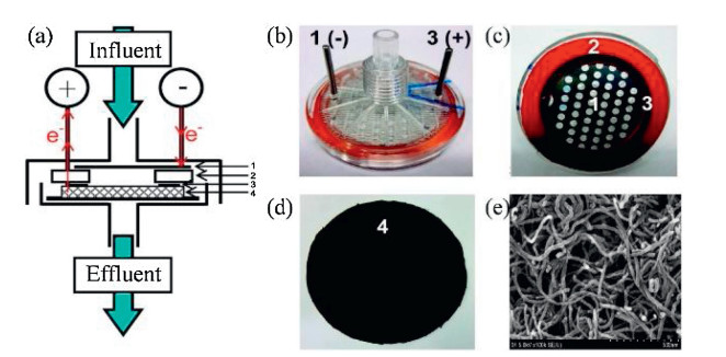
Figure 1.
Depiction and images of the electrochemical filtration apparatus. (a) Design of the modified commercial polycarbonate cathode, (2) an insulating silicone rubber separator and seal, (3) a titanium anodic ring that is pressed into the carbon nanotube anodic membrane, and (4) the MWNT anodic membrane supported by a PTFE membrane. (b, c) Images of the modified filtration casing. (d, e) Digital photograph and FESEM of the MWNT network electrochemical filtration, respectively. (a-d) are reproduced with permission [62]. Copyright 2011, American Chemical Society. (e) is reproduced with permission [66]. Copyright 2019, Elsevier.
The electrochemical CNT membranes have demonstrated to be capable of degrading several refractory compounds and emerging contaminants by direct electron-transfer (DET) or production of reactive species (e.g., HO·, HO2·, Cl·, SO4·-) [62, 67, 68]. It is noteworthy that conventional electrochemical systems usually employ two plate electrodes and operates in a flow-by mode. Such configuration usually results in a relatively large hydrodynamic diffusive boundary layer (e.g., >100 μm), significantly limiting the removal of pollutants. However, theoretical modeling and experimental investigations suggest that the oxidative reaction only occurs within 1 μm of the anode surface [69]. The reactions occur only at or near the electrode surface, and a thick boundary layer will substantially decrease the degradation efficiency of organic pollutants. Electrochemical filtration technology combines membrane filtration with electrooxidation and offers an alternative when operating in a flow-through mode. In this case, the boundary layer thickness could be significantly minimized to less than 1 mm, due to convection-enhanced mass transport of target compounds toward the surface active sites of the membrane.
A schematic illustration of a typical electrochemical filtration apparatus is shown in Fig. 1. A commercial filtration system with a polycarbonate membrane was modified to allow for electrochemical reaction. The operating mechanism of the electrochemical CNT membrane includes four steps [65]: (1) Mass transport of target molecules towards the CNT membrane, (2) adsorption to the surface active sites, (3) electrooxidation at the membrane surface, and (4) desorption from the membrane to replenish the active sites. Preliminary studies demonstrated that the electrochemical CNT membranes are effective for adsorption and electrooxidation of dyes, pharmaceuticals, organic compounds, and heavy metal ions. For example, Tan et al. used the electrochemical CNT membrane system to degrade a series of antibiotics (e.g., sulfamethoxazole, ciprofloxacin, and amoxicillin) from aqueous solution [70]. At 3 V, the electrochemical CNT membrane is capable of degrading a cocktail of antibiotics with an efficiency of 98% for amoxicillin, 95% for sulfamethoxazole, and 20% for ciprofloxacin. An electrochemical filtration of 0.2 mmol/L tetracycline at a total cell potential of 2.5 V and a flow rate of 1.5 mL/min (hydraulic residence time < 2 s) resulted in an oxidative flux of 0.03 mol h-1 m-2 and a >95% tetracycline oxidation just by a single pass through the CNT membrane [57].
CNT is considered as an "active" electrode and one of the most widely used electroactive membrane materials. However, there are still certain limitations need to be addressed when compared to the other carbon-based and/or ceramic membrane materials. Firstly, the electroactive CNT membranes usually suffer from poor connectivity because of the weak van der Waals forces that limit their electronic conductivity [76]. Secondly, the electroactive CNTbased membrane could be leached into effluent during operation and the cytotoxicity of CNT to aquatic organism still under debate [87]. This need to be addressed before practical applications of this promising technology. Therefore, the development of composite CNT materials using polymeric binders such as polyvinylidene fluoride (PVDF) to stabilize CNT may prevent the leakage of CNT and secure the membrane conductivity to some extent [88]. Thirdly, the CNT only provides a limited oxygen evolution potential (OEP, 1.25 V) [79], which may lead to low current efficiency at elevated anode potentials due to competition with anode corrosion and water oxidation. Similarly, at more negative potentials, the hydrogen evolution reaction may also compete with any desirable electroreduction reactions for electrons (e.g., 2-electron O2 reduction). In contrast to CNT, the boron-doped diamond (BDD)
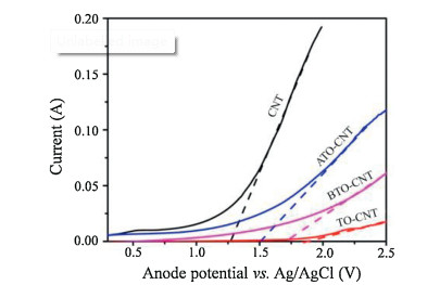
(2.3 V vs. standard hydrogen electrode (SHE)) and Ti oxides (e.g., Ti4O7 of 2.2-2.7 V vs. SHE) electrodes has a higher OEP, which shown high yields of HO· although their cost is higher and mostly only support a flow-by operation [22, 89]. To further expand the electrochemical window of CNT, an "electrosorption-hydrothermal" strategy was proposed to load nanoscale SnO2 and Bi-doped SnO2 onto the CNT sidewalls [79]. The electrochemical characterization of the modified electrode material confirmed that the stability of the composite membrane was indeed improved after modification, with OEP increased from 1.27 V (vs. Ag/AgCl) of CNT to 1.71 V (vs. Ag/AgCl) of Bi-SnO2-CNT (Fig. 2). Meanwhile, it has been reported that the nanoscale zero-valent iron (nZVI) modified CNT membrane also demonstrated enhanced electrooxidation performance than that of pristine CNT alone membrane at an applied potential of +1.0 V with a degradation efficiency of metoprolol increased from 74% to 97% [60]. It is, therefore, reasonable to hypothesize that other nanoparticles with higher OEP could also be applied for CNT modification to improve the current efficiency as well as the electrode stability. In addition, CNT doping with boron (B-CNT) or nitrogen (N-CNT) has been observed to affect the CNT electronic structure and in turn to affect the electrochemical activity of CNT. This could change the conductivity and specific capacitance—two properties that directly correlates to electrochemical performance of CNT. For example, an 8 mgC/L removal of total organic carbon (TOC) was achieved within 1 s retention time when a 3 V cell potential was applied on the N-CNT membrane [90].
Figure 2
Figure 2.
The linear sweep voltametry (LSV) curve of the CNT and CNT-based anode materials. Reproduced with permission [79]. Copyright 2013, American Chemical Society.
Besides anodic oxidation of pollutants, the cathodic reduction is also an important but often overlooked aspect within an electrochemical system. Since the cathode provides electrons, it supports reduction reaction and cannot directly be used to oxidize the hydrocarbon contaminants. CNT based-materials are considered as the next-generation of oxygen reduction reaction (ORR) catalysts. By the two-electron reduction pathway, a CNT functional cathode enables a selective generation of hydrogen peroxide (H2O2, see Eq. 1).
(1)
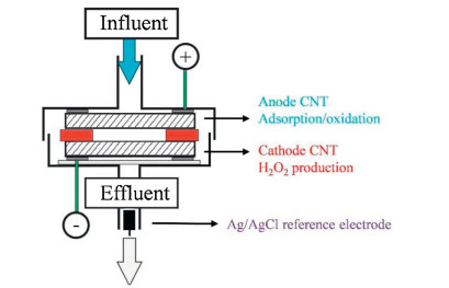
As a moderate oxidant (E0 = 1.76 V vs. SHE), H2O2 can directly oxidize some organic pollutants. For instance, we have described the rational design of a flow-through CNT-based electrochemical system using a CNT membrane serving as anode and cathode, respectively [91]. This system combines a first oxidative reaction at the CNT anode and additional oxidation at the CNT cathode with the H2O2 generated in situ (Fig. 3). Using phenol as a model contaminant, an average oxidation rate of 0.059 mol h-1 m-2 and an average removal efficiency of 87%, was obtained over 4 h of continuous operation. The phenol oxidation flux correlated with the H2O2 generation flux. In a conventional batch system, phenol negligibly removed by spiked H2O2. The maximum generation rate of H2O2 was at neutral pH, vastly different from a conventional Fenton system with optimal H2O2 yield at a pH of 3. It highlights the potential of this system for practical engineering applications.
Figure 3
Figure 3.
Scheme of the electrochemical carbon nanotube membrane coupled with insitu generated H2O2. Reproduced with permission [91]. Copyright 2015, The Royal Society of Chemistry.
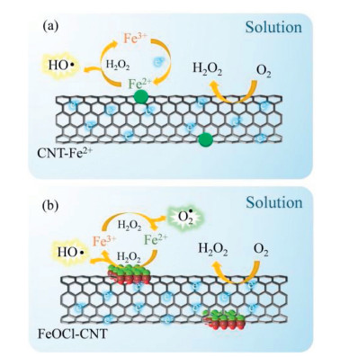
To better utilize these as-produced H2O2, functionalization of the CNT cathode with effective Fenton catalysts has also been explored. H2O2 generated in situ can be further decomposed to produce HO· and induce Fenton reaction (Eqs. 2-4) [92, 93]. Gao et al. used a ferrous ion chelated CNT (CNT-COOFe2+) functional cathode and a similar electrochemical filtration device to achieve sequential electro-Fenton reaction for degradation of refractory contaminants [78]. In this design, the CNT-COOFe2+ cathode not only reduce H2O2 to HO· but also regenerates ferrous ions by an applied electric field (Fig. 4a). The sequential electro-Fenton reaction was compared with the single processes using oxalate as a model molecule, appreciating a synergistic effect. Under optimal conditions, the corresponding oxidation rate for oxalate by the sequential electro-Fenton process was 207 mgC m-2 h-1, 4-fold higher than the sum of the individual oxidation rates by electrochemistry (16 mgC m-2 h-1 and Fenton (33 mgC m-2 h-1) reaction fluxes. However, due to the continuous replenishment of water on the membrane surface, the loss of ferrous ions seems inevitable, reducing the long-term stability of the hybrid membrane cathode. The main challenge in this context is to develop a heterogeneous Fenton-like catalyst of high-performance with desirable reactivity and stability.
(2)
(3)
(4)
Figure 4
Figure 4.
Schematic diagram of the degradation mechanism of organic pollutants by the membranes (a) CNT-COOFe2+ and (b) FeOCl-CNT. (a) is reproduced with permission [78]. Copyright 2015, American Chemical Society. (b) is reproduced with permission [73]. Copyright 2020, Elsevier.
To address this issue, Li et al. proposed another design of the flow-through electro-Fenton system based on a CNT membrane cathode functionalized with iron oxychloride (FeOCl) catalysts at the nanoscale [73]. FeOCl is a novel and promising twodimensional material with desirable physicochemical properties. The effectiveness of FeOCl towards H2O2 decomposition is well documented [94, 95]. Herein, dissolved O2 in the influent can be insitu reduced to H2O2 upon application of a proper negative potential. Then, the produced H2O2 could be efficiently decomposed by the nanoscale FeOCl catalyst to produce HO· together with the cycling of Fe3+/Fe2+. Finally, target molecules could be effectively degraded by HO·, and the regeneration of Fe2+ could be facilitated by the electric field (Fig. 4b). In contrast to a conventional batch reactor, the proposed system demonstrated superior degradation efficiency for pollutants due to convectionenhanced mass transport, as well as a desirable reactivity and stability of the FeOCl nanocatalysts. Given the excellent performance, this technology could potentially be an effective wastewater treatment system.
4.
Decontamination of heavy metal ions
A high concentration of heavy metal ions (e.g., arsenic (As), chromium (Cr), and antimony (Sb)) in water bodies can pose a public health concern [96]. Sorption is an appealing procedure due to its ease of operation and cost-effectiveness [97, 98]. Meanwhile, compared with previous adsorbents (e.g., activated carbon, resin and chitosan) [99], CNT composite materials were favored by researchers because of their scale effect, large specific surface area, strong interface interaction and unique physical and chemical properties [100, 101]. Functionalization of CNT with chemical groups effectively enhanced the adsorption capacity of CNT membranes towards the heavy mental ions due to increased anchoring sites [102]. Moreover, the adsorption efficiency and rate could be further improved by utilizing the unique electrical conductivity of CNT (e.g., electrostatic interaction) and the application of the electroactive CNT membrane technology for the removal of heavy metal ions has been extensively explored [103, 104]. Various metal oxide sorbents at the nanoscale, including MnO2, ZrO2, Fe3O4, and TiO2, with high affinity to specific heavy metal ions, have been developed [105-107]. Despite the progress, the sluggish kinetic of adsorption obtained in the conventional systems limits a wider application of this technology. The required time to reach equilibrium is usually from hours to even few days for certain promising sorbents (powder and/or granulate) due to poor mass transport as well as sorbents agglomeration [108]. For example, Deng et al. reported a sorption equilibrium time of 12 h for As(V) when Ce-Ti oxide binary adsorbent was used [109]; the Sb(Ⅲ) adsorption equilibrium was as long as 24 h at natural conditions, due to the limitation of mass transport, when employing a kaolinite-based sorbent [110]. If the sorbent and sorbate have the same polarity, the removal kinetics would be further decreased due to electrostatic repulsion. Moreover, nanoscale adsorbents can hardly be applied directly into operative conditions due to the additional effort needed for a postseparation. To address this issue, sorbents have either been attached to porous substrates, blended into membranes, and/or encapsulated into microporous polymers [111, 112]. Unfortunately, these designs usually sacrifice the overall treatment performance due to the inevitable blocking of the sorption sites. On the other hand, the speciation of heavy metal ions strongly correlates with their physicochemical properties. For example, Cr(Ⅵ) is soluble and has toxic and carcinogenic effects, while its Cr(Ⅲ) counterpart is less toxic and less soluble. Similarly, in comparison to Sb(V), Sb(Ⅲ) is 10 times more toxic, and its removal efficacy by sorption is generally low due to a predominant charge-neutral state across a broad pH range (e.g., 3-9) [113, 114]. In these cases, both adsorption of heavy metal ions and detoxification are required. The conventional method usually includes an additional chemical treatment unit to detoxify heavy metal ions, which undoubtedly increases the operational complexity and cost.
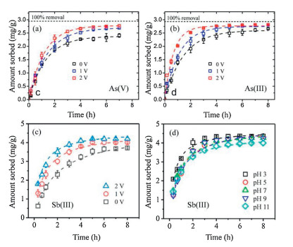
Vecitis et al. proposed a TiO2-coated CNT membrane for rapid and effective sorption of As as an alternative to solve mass transport limitation [84]. The major advantages of the composite membrane are small pore size, accessible sorption sites, and limited diffusion length. They found that the TiO2-CNT increased sorption kinetics for As with increasing flow rate. When compared to granular sorbent TiO2, the TiO2-CNT membrane provided a 127- fold increase in the sorption rate of As. The sorption kinetics of As could be further enhanced by applying an external electric field due to anodic capacitive charging, increasing electromigration, and reducing negative surface charge. Using TiO2-CNT, the equilibrium sorption capacities at 2 V was increased by 11.1%, and 38.5% for As(Ⅲ), and As(V), respectively, when compared with that of 0 V (Figs. 5a and b). Furthermore, such flow-through design enables an empty bed contact time (EBCT) of only 4.5 s at a flow rate of 1.5 mL/min. This value is 1-2 orders of magnitude lower than the obtained using a conventional granular column EBCT (1.5-15 min)[115].
Figure 5
Figure 5.
TiO2-CNT membrane for As and Sb(Ⅲ) sorption kinetics. (a) As(V), (b) As(Ⅲ) and (c) Sb(Ⅲ) at 0, 1, and 2 V in recirculation mode. (d) Effect of pH of 3-11 on Sb(Ⅲ) sorption in recirculation mode. (a, b) were reproduced with permission [84]. Copyright 2014, American Chemical Society. (c, d) were reproduced with permission [85]. Copyright 2019, American Chemical Society.
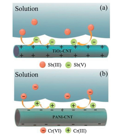
Thanks to the electrochemical activity of the membrane materials, an electrochemical-assisted filtration system may simultaneously induce redox reactions to detoxify selected heavy metal ions while passing through. Therefore, the bifunctional membrane enables simultaneous adsorption and detoxification of heavy metal ions. Liu et al. recently developed an electrochemical system composed of a TiO2-CNT membrane anode and a Ti cathode to remove Sb(Ⅲ) [85]. Upon application of an external electric field (e.g., 2 V), in situ transformation of highly toxic Sb(Ⅲ) to less toxic Sb(V) can be achieved, which is further sequestered by nanoscale TiO2 due to their high affinity (Fig. 6a). For example, at 2 V, removal of Sb(Ⅲ) >95% is obtained over 8 h continuous filtration, being remaining Sb(V) the dominant specie rather than Sb(Ⅲ), and indicating that the oxidation reaction is active during the filtration process. Interestingly, both Sb(Ⅲ) sorption kinetics and capacity increased with voltage. The applied voltage increased qe from 3.3 mg/g at 0 V to 4.2 mg/g at 2 V; meanwhile, the time required to achieve equilibrium also decreased from >8 h at 0 V to 3 h at 2 V (Fig. 5c). System operability can be expanded both in a wider pH range and environmental matrixes (Fig. 5d). If nanoscale TiO2 particles are replaced by another nanoscale Sb specific sorbents such as titanate nanowires or iron oxides, comparable or even higher performance can be achieved [116, 117]. In addition, the photoelectrochemical synergistic effect could further boost the system performance by loading some photo-responsive nanomaterials (like metal organic frameworks (MOFs)) onto the CNT matrixes. As a proof-of-concept, Li et al. fabricated a photoelectrical-responsive CNT filter functionalized with nanoscale MIL- 88B(Fe) photocatalysts, which demonstrated excellent performance towards "one-step" detoxification and sequestration of highly toxic Sb(Ⅲ) [118].
Figure 6
Figure 6.
The mechanism of (a) oxidation/(b) reduction and adsorption simultaneously for highly toxic Sb(Ⅲ) or Cr(Ⅵ) using electroactive membranes TiO2-CNT and PANI-CNT. (a) is reproduced with permission [85]. Copyright 2019, American Chemical Society. (b)is reproduced with permission [66]. Copyright 2019, Elsevier.
A similar concept could also be applied for "reduction-sorption" applications once the functional membrane served as a cathode. For example, Cr(Ⅵ) is carcinogenic, and 500-1000 times more toxic than Cr(Ⅲ) [119]. We have recently developed a dualfunctional electrochemical membrane system that enables Cr(Ⅵ) detoxification and sequestration (Fig. 6b) [66]. The key to this technology is an electrochemical CNT membrane functionalized with nanoscale polyaniline (PANI). The amine and imine moieties of PANI can chelate and further reduce metal ions, although the reduction efficacy is usually limited by pH of 1-3. As a fitting solution, an electric-assisted flow-through system was rationally designed employing a PANI-CNT hybrid membrane as the functional cathode. Both the reduction kinetics for the Cr(Ⅵ) and the sorption capacity of the Cr(Ⅲ), were enhanced with flow rate and voltage increased. For example, there is a complete reduction of the Cr(Ⅵ) at 2.5 V and pH 7, much higher than that of 78.0% at 0 V under similar conditions. The equilibrium times were >5 h (at 0 V) and 4 h (at 2.5 V) with a k value of 0.59 and 0.73 h-1, respectively. Moreover, the removal efficiency of the total chromium (or Crtotal) can be further improved by applying an electric field. At pH 7, Crtotal removal efficiency increased from 29.3% at 0 V to 70.2% at 2.5 V. More importantly, the energy consumption of this system was 0.032 kWh/m3, much lower than state-of-the-art treatment technologies. A PVA-CNT composite UF membrane was used to electrochemical reduce and remove Cr(Ⅵ). The removal mechanism is highly dependent on the solution conductivity, with higher solution conductivity leading to increased Cr(Ⅵ) reduction and Cr(Ⅲ) precipitation on the membrane surface. Meanwhile, the energy needed to remove 1 ppm of Cr(Ⅵ)
(> 99%) from tap water was determined to be 1.48 kWh/m3, less than other alternative processes (e.g., ion exchange and reduction/coagulation processes) [86]. Thus, the electroactive membrane reduction technology is a cost-effective and promising strategy for the detoxification of heavy metals. Both the rapid kinetics and superior performance suggests that the electrochemical CNT membrane may provide an affordable and promising solution for the removal of heavy metal ions from water.
5.
Construction of electroactive antifouling membranes
Membrane processes hold great promise to address the challenging issue of water scarcity. Unfortunately, since the birth of membrane technologies, fouling has consistently been the bottleneck restricting process efficiency by reducing water permeation flux and water quality, and increasing energy consumption. Membrane fouling can be caused by pore blocking, adsorption of organic compounds, precipitation of inorganic substances, and/or biological accumulation, leading to temporary or permanent flux decline [120-122]. The development of antifouling membranes is essential for addressing this challenging issue.
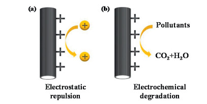
Among the available methods, the electroactive antifouling membrane is an attractive solution. Generally, the membrane materials need to be modified with a conductor (e.g., activated sludge, PANI and TiOx) for allowing the application of an electric field without sacrificing desirable membrane properties [123, 124]. Compared with other conductors, CNT offers new opportunities for constructing advanced electroactive antifouling membranes. The over-lapping and reticular structure of CNT enable the electroactive membrane to have high porosity and abundant interconnected pores [125], which leads to high water flux even at low operating pressure. In addition, CNT have excellent electrochemical properties and can transfer electrons quickly [126]. Furthermore, by using the membrane itself as an electrode material, the electric field can be applied more effectively and straightforward. Therefore, the application of an external electric field (DC or AC) to a CNT membrane have demonstrated to be effective for reducing fouling and increasing the permeate flux rates [127, 128]. Electrochemistry plays two dominant roles in the antifouling function: 1) Like-charge repulsion and 2) electro-induced oxidation (Fig. 7) [28, 129]. On one hand, increased electrostatic repulsion between membrane surface and foulants could alleviate both pores blocking and surface gel formation. Jassby et al. reported that a conductive UF membrane is capable to alleviate the deposition of negativelycharged sodium alginate upon the application of a DC voltage of ‒3.5 V [28]. Liu et al. developed a robust electroactive thin-film composite (TFC) forward osmosis (FO) membrane, with good resistance to bovine serum albumin (BSA) under 2.0 V DC voltage, when the membrane-electrode assembly was deployed as a functional cathode [130]. On the other hand, CNT could also induce oxidation effect under electric field to achieve self-cleaning. Vecitis et al. found that an electrochemical CNT membrane enables rejection and inactivation of bacteria (Escherichiacoli) and virus (bacteriophage MS2) [54]. The primary mechanism of electrochemical inactivation at a lower voltage (e.g., 1 V and 2 V) provokes a direct oxidation of pathogens, while that at a higher voltage (e.g., 3 V) may be originated from the generation of reactive oxygen species (ROSs, e.g., HO·, Cl·, and SO4·-). Similarly, Ni et al. reported a complete inactivation of Escherichiacoli (>6 log) at a voltage of 3 V and a flux of 120-3600 L m-2 h-1 using a graphitized carbon felt membrane electrode [131]. Long-term (24 h per day, 7 days) treatment of a solution with an Escherichiacoli concentration ranging from 106 to 107 CFU/mL at 3 V and a flow rate of 20 mL/min, caused inactivation of bacteria in the effluent. It shows the superior stability of the flow-through system for water disinfection applications [132]. To deal with mineral scaling, Duan et al. reported that a CNT-polyamide membrane anode that enabling effective removal of CaCO3 scale deposited on the membrane surface at 2.5 V due to the formation of localized H+ [133]. Meanwhile, an opposite design was used to manage silica scaling on CNT-PVA membrane when treating geothermal brines. The electroactive membranes were used as cathodes, which resulted in water electrolysis and the formation of OH-, so that the membrane flux recovered rapidly due to the dissolution of silicate gel at increased pH conditions [134].
Figure 7
Figure 7.
The mechanism of (a) oxidation/(b) reduction and adsorption simultaneously for highly toxic Sb(Ⅲ) or Cr(Ⅵ) using electroactive membranes TiO2-CNT and PANI-CNT. (a) is reproduced with permission [85]. Copyright 2019, American Chemical Society. (b)is reproduced with permission [66]. Copyright 2019, Elsevier.
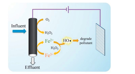
o mitigate fouling without sacrificing the membrane flux, Yang et al. developed a novel design of anaerobic electrochemical membrane bio-reactor (MBR) employing a CNT-based hollow fiber cathode [63]. At -1.2 V, this system provides slower transmembrane pressure (TMP), increasing rates, and better TMP recovery, with a >95% chemical oxygen demand (COD) removal efficiency over the 100-day operation. They suggested that the electrostatic repulsion force pushing negatively-charged extracellular polymeric substances (EPS) away from the membrane, thereby hindering the formation of a gel layer and mitigating membrane pore blocking in the anaerobic electro-assisted MBR. By further integrating porous carbon with CNT cathode and coupling with Fe2+, in situ electro-Fenton reaction was induced for the degradation of deposited pollutants (Fig. 8). In this case, the effluent quality enhances, and membrane fouling is mitigated due to the sustainable production of highly reactive HO·. At -0.8 V, the removal efficiency for protein, glucose, and phenol using the membrane system was 2.7, 6.2, and 9.7 times higher than that of separation only system [64]. Beyond this, the same authors also designed another aerobic MBR system using the CNTs-based hollow fiber as anode. At +1.0 V, the electroactive aerobic MBR system not only shows higher water flux, but also an enhanced rejection efficiency of selected foulants [83]. Overall, CNT appear to be the most promising carbon materials for the fabrication of antifouling membranes. Subsequent research should be focused on the upscaling of the prototypes for practical engineering applications.
Figure 8
Figure 8.
Conceptual illustration of the electro-Fenton assisted PC-CNT hollow fiber membrane for fouling suppression using in situ generated HO·. Reproduced with permission [64]. Copyright 2019, Elsevier.
The cost of electroactive CNT-based membranes mainly consists of two parts, i.e., materials cost and energy consumption. On one hand, the fabrication of CNT-based membrane involves additional cost of adding a CNT layer on top of a porous support. It has been calculated that CNT of 0.66 g might be used to form a 1 μm thick CNT layer on a 1 m2 area, which means that the materials cost will be $1.83/m2, which is only ~7% of the cost of a commercial UF membrane [32]. In addition, it is possible to achieve large-scale deposition of CNT using current modern technologies (e.g., spray coating), which does not entail excessive technical obstacles and cost budgets. Importantly, the mass production of CNT has also advanced progressively and is readily available for purchase at kilogram level. Therefore, CNT should not become a barrier to the commercialization of electroactive CNT-based membranes. It should be also noted that, if the electroactive CNT-based membrane is needed to operate at high potential, a counter electrode with corrosion resistance (e.g., titanium electrode) should be required as well, which would undoubtedly increase the material costs.
In addition to the cost of the raw material, energy consumption is also an important part. Since only a limited electric field was exerted on the CNT membranes (e.g., 1-3 V), and the energy consumption was mostly < 0.5 kWh/m3 [28, 85]. This number is lower than or comparative with other electrochemical processes with the energy consumption of 0.1-10 kWh/m3 [135]. Therefore, electroactive CNT-based membranes offer a cost-effective and environmentally friendly alternative to wastewater treatment.
7.
Outlook and challenges
Currently, many companies are investing in the diverse applications of CNT membranes, such as energy storage, wastewater treatment, novel coating, electronic components, biotechnology, etc. For example, the CNT membranes of transparent and conductive with high surface resistivity can be used as an alternative to indium tin oxide (ITO) due to the growing demand of touch-screen devices and photovoltaics [136]. The CNT thin membrane transistors (TFTs) have presented higher mobility than amorphous silicon (~1 cm2 V-1 s-1), which are particularly attractive for driving organic light-emitting diode (OLED) displays [137]. Therefore, the rapid development of CNT membranes will make the production process simpler, cheaper and more resource-efficient.
While the literature has reported that electrochemical CNT membranes have several unique advantages and served as a promising process for water purification, the technology still exhibits several challenges that need to be further optimized.
Firstly, the cost of CNT and environmental impacts of the technology should be further decreased. Nowadays, the price of CNTs has significantly decreased due to the improvement of CNTs mass-production technology, although the price is still far higher than that of activated carbon and other carbon materials. The electrochemical oxidation process may not be able to directly mineralize some refractory compounds into CO2 and potentially may lead to secondary pollution of water due to the generation of by-products or intermediates [138]. This should be taken into consideration, especially for the treatment of wastewater containing halogen ions. For example, chloride in aqueous can be oxidized to form toxic chlorate and perchlorate ions, subject to water legislation [139, 140]. Although ongoing interest in CNT as components of wastewater treatment equipment is motivated by the mechanically and electrochemically robust networks with controlled nanoscale porosity of CNT. However, as large quantities of CNT materials enter into consumer market, some industries for processing and reusing CNT will also be required. The CNT may enter the sewer pipes and, unless incinerated, may cause crosscontamination during the recovery process. Thus, a broader communication platform between industry, academia and government is needed to study the environmental and social risk of CNT throughout their life cycle.
Secondly, most of the electroactive membrane technologies were conducted only in laboratory conditions and at bench-scale. Also, the study of their applications is limited to the removal of one or a few components from synthetic wastewater. Performance may fail in real conditions for the treatment of industrial wastewater with more complex compositions. Natural organic matters may reduce the performance significantly by scavenging ROS and active sites on the membrane surface. Membrane fouling is a key issue that hinders the large-scale application and needs to further be addressed. Fouling is problematic for both ceramic and polymeric membranes, where colloids, macromolecules, and microorganisms cause the formation of fouling layers. When dealing with aromatic compounds or natural organic matter, those have strong π-π interaction with the sp2-conjugated CNT sidewalls, and in the case of aromatic compounds, these cannot be effectively removed even by chemical washing. Furthermore, to ensure high flux and long durability in pilot scale experimentation, other robust membranes, such as ceramic can be used as mechanical support or as throughflow membrane materials after chemical modification.
Thirdly, most of the CNT membranes are disordered 3D networks with macroscale pores. There is a need for a more comprehensive effort to the nanostructuring of CNT membranes, for example with lithographic technology or in situ chemical vapor deposition (CVD) technique to synthesize well-aligned CNT nanoarrays. In that case, the filtration process could be precisely controlled at molecular level. In addition, mechanic and theoretical approaches provide new insights and understanding for the rational design of advanced electroactive membrane systems towards point-of-use applications.
8.
Conclusions
The excellent properties of CNT such as self-cleaning, reactive, antifouling and multifunction, endow them as a promising class of membrane materials for water remediation. The capability to integrate electrochemistry and membrane separation opens new water treatment options and enables process intensification. The flow-through design allows the combined advantages of convection-enhanced mass transport and large accessible electroactive sites. The applied electric field could be directly delivered to the membrane/water interface, where separation and redox reactions occur. There is a need for comprehensive efforts to provide mechanistic insights on the "microstructure-performance" relationship on the rational design of CNT membranes. This review may improve the knowledge of next-generation water remediation technology and may provide the know-how on developing practical and useful devices.
Declaration of competing interest
The authors declare that they have no known competing financial interests or personal relationships that could have appeared to influence the work reported in this paper.
Acknowledgments
This work was supported by the Natural Science Foundation of Shanghai, China (No.18ZR1401000), the Shanghai Pujiang Program (No. 18PJ1400400), and Y. Liu thanks Donghua University for the start-up grant (No. 113-07-005710).
O. Azizi, D. Hubler, G. Schrader, et al., Environ. Sci. Technol. 45(2011) 10582-10590. doi: 10.1021/es202534w
Figure 1
Depiction and images of the electrochemical filtration apparatus. (a) Design of the modified commercial polycarbonate cathode, (2) an insulating silicone rubber separator and seal, (3) a titanium anodic ring that is pressed into the carbon nanotube anodic membrane, and (4) the MWNT anodic membrane supported by a PTFE membrane. (b, c) Images of the modified filtration casing. (d, e) Digital photograph and FESEM of the MWNT network electrochemical filtration, respectively. (a-d) are reproduced with permission [62]. Copyright 2011, American Chemical Society. (e) is reproduced with permission [66]. Copyright 2019, Elsevier.
Figure 2
The linear sweep voltametry (LSV) curve of the CNT and CNT-based anode materials. Reproduced with permission [79]. Copyright 2013, American Chemical Society.
Figure 3
Scheme of the electrochemical carbon nanotube membrane coupled with insitu generated H2O2. Reproduced with permission [91]. Copyright 2015, The Royal Society of Chemistry.
Figure 4
Schematic diagram of the degradation mechanism of organic pollutants by the membranes (a) CNT-COOFe2+ and (b) FeOCl-CNT. (a) is reproduced with permission [78]. Copyright 2015, American Chemical Society. (b) is reproduced with permission [73]. Copyright 2020, Elsevier.
Figure 5
TiO2-CNT membrane for As and Sb(Ⅲ) sorption kinetics. (a) As(V), (b) As(Ⅲ) and (c) Sb(Ⅲ) at 0, 1, and 2 V in recirculation mode. (d) Effect of pH of 3-11 on Sb(Ⅲ) sorption in recirculation mode. (a, b) were reproduced with permission [84]. Copyright 2014, American Chemical Society. (c, d) were reproduced with permission [85]. Copyright 2019, American Chemical Society.
Figure 6
The mechanism of (a) oxidation/(b) reduction and adsorption simultaneously for highly toxic Sb(Ⅲ) or Cr(Ⅵ) using electroactive membranes TiO2-CNT and PANI-CNT. (a) is reproduced with permission [85]. Copyright 2019, American Chemical Society. (b)is reproduced with permission [66]. Copyright 2019, Elsevier.
Figure 7
The mechanism of (a) oxidation/(b) reduction and adsorption simultaneously for highly toxic Sb(Ⅲ) or Cr(Ⅵ) using electroactive membranes TiO2-CNT and PANI-CNT. (a) is reproduced with permission [85]. Copyright 2019, American Chemical Society. (b)is reproduced with permission [66]. Copyright 2019, Elsevier.
Figure 8
Conceptual illustration of the electro-Fenton assisted PC-CNT hollow fiber membrane for fouling suppression using in situ generated HO·. Reproduced with permission [64]. Copyright 2019, Elsevier.

 DownLoad:


 下载:
下载:


