Figure 1.
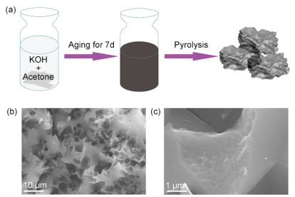
(a) Schematic illustration of the synthesis of ADPC, (b) and (c) SEM images of ADPC-8.
A high-performance potassium-ion capacitor based on a porous carbon cathode originated from the Aldol reaction product
Xu Yu , Mingjie Shao , Xuemei Yang , Chongxing Li , Tong Li , Danyu Li , Rutao Wang , Longwei Yin

Nonaqueous metal-ion capacitors, which are energy storage devices that are generally composed of a battery-type anode and electric double-layer capacitor (EDLC)-type cathode, have attracted widely attention thanks to their advantages of both high-power density of EDLCs and high energy density of batteries [1, 2]. Up to now, various nonaqueous metal-ion capacitors have been developed, such as the monovalent (Li+, Na+, K+) and/or multivalent (Mg2+, Zn2+) cations [1, 3-5]. Among these metal-ion capacitors, developing K-ion capacitors (KICs) is high desirable because of the following two important factors. One is that the redox potential of K is -2.93 V (vs. E0) which is the nearest to Li (-3.04 V vs. E0), lower than Na (-2.71 V vs. E0), Mg (-2.37 V vs. E0), Zn (-2.3 V vs. E0) and Al (-1.66 V vs. E0) [6]. Secondly, K is abundant and geographically ubiquitous in earth. The crust abundance of potassium (1.5%, the 7th in CLARKE value) is much higher than that of lithium (0.0017%) and comparable to that of their Na counterparts (2.3%), endowing KICs with potentially low cost and sustainability [3, 7]. However, the low capacity of EDLCs' cathode leads to the capacity imbalance between the anode and cathode, presenting the major problem to develop advanced KICs with high energy density.
According to the charge storage mechanism of EDLCs' electrode, the capacitive performance of EDLCs' electrode is strongly related to the surface area and pore structure, especially in organic electrolytes [8]. Activated carbon (AC) is a commercially available EDLCs' cathode materials for metal-ion capacitors, however, AC only delivers 40-60 mAh/g in organic electrolytes caused by its relatively low Brunauer-Emmett-Teller (BET) specific surface area (SSA) of 1000-2000 m2/g [9]. Research has thus been focused on developing porous carbons with large BET SSA to achieve the desired capacitive performance. Various porous carbons derived from biomass [10], graphene [11], MOFs [12] and polymers [13] have reported higher BET SSA values than that of AC, exhibiting high-end capacitance values over 60 mAh/g in Li+ or Na+ based organic electrolytes. However, little attention has been paid to these porous carbons operating in K+ based organic electrolytes, being really a large drag on the development of high energy density KICs. Furthermore, the high cost and complex preparation process of mass production of high-quality porous carbon is still a challenge for the commercialization of KICs.
In this work, we present a simple and effective strategy to synthesize porous carbon from the Aldol reaction product of acetone with KOH. The obtained porous carbon has an extremely high nitrogen BET SSA value of 2947 m2/g and a well-controlled pore size ranging from 1 nm to 3 nm. Such porous carbon electrode shows the typical EDLC behavior with the large specific capacity of 91.3 mAh/g and high rate capability in standard two-electrode system (vs. K/K+), making it an ideal cathode material to mind the capacity gap with anode material. A novel KIC is thus fabricated by employing acetone derived porous carbon (ADPC) as the cathode and N, P co-doped carbon as the anode, which exhibits the very competitive performance in energy density and power density.
The acetone derived porous carbon (ADPC) was prepared through Aldol reaction and followed chemical activation reaction, as shown in Fig. 1a and Fig. S1 (Supporting information). Under alkaline condition, Aldol reactionwas initiated, and acetone was polymerized into cream-like products composed by unknown oligomers [14]. The cream-like products without any purification were directly used as the precursors to produce the porous carbon through the high-temperature chemical activation reaction. The potassium deviates rooted in the Aldol reaction worked as the chemical activated agent. The scanning electron microscopy (SEM) images in Figs. 1b and c show the typical ADPC-8 sample exhibits the bulk morphology with irregular shapes with sharp corners. Transmission electron microscopy (TEM) images (Fig. S2 in Supporting information) show ADPC-8 has a dense porous structure with highly curved, atomic-thick carbon nanosheets. The X-ray diffraction (XRD) pattern of asprepared ADPC-8 (Fig. 2a) only shows two broad diffraction peaks at 22° and 43°, corresponding to the (002) and (100) diffraction patterns of graphitic carbon, respectively, indicating the amorphous and defective nature. Furthermore, Scherrer' equation was used to evaluate the average graphene domain height (Lc) of ADPC-8, using the full width a half maximum value of (002) peaks [15]. The Lc value for ADPC-8 is about 1.06 nm, which indicates that the graphene domains for ADPC-8 sample are mainly composed of three layered stacked curved graphene sheets (e.g., 1.06/0.34 = 3.11).
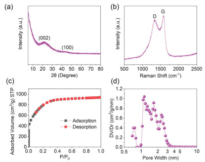
Raman spectroscopy was further employed to investigate the carbon structure of ADPC-8, and the corresponding results are shown in Fig. 2b. The Raman pattern of ADPC-8 shows the characteristic peaks at ~1350 and 1853 cm-1, which can be assigned to D-band (represented sp3-bonded carbon at the edge of a graphene layer) and G-band (represented sp2-boned ideal graphitic carbon) of carbon, respectively [16, 17]. A high intensity ratio ID/IG indicates a high degree of disorder in relation to graphitization [17]. ID/IG value is calculated to be 1.75, suggesting the amorphous nature for ADPC-8. In addition, the average domain size (La) was obtained by the equation (La (nm) = (2.4 × 10⁻¹⁰)λ4(ID/IG)-1) [17]. The La value for ADPC-8 is ~11.2 nm, which is close to that of other reports on KOH activated porous carbons [12, 15, 18].
Fig. 2c shows the nitrogen sorption isotherm curve of ADPC-8 sample. ADPC-8 sample shows a type-Ⅰ isotherm for microporous characteristic. The chemical activation process yields an extremely small-size pores, ranging from ~1 nm to ~3 nm, as shown in Fig. 2d. ADPC-8 has the high nitrogen BET surface area of ~2947 m2/g and a large pore volume of 1.45 cm3/g. To further study the effect of KOH addition on the pore structure of ADPC, a serious of similar experiments with the different mass of KOH addition were carried out (Fig. S3 and Table S1 in Supporting information). At the low mass of KOH addition, the BET surface area value of ADPC-4 and ADPC-6 is not over 1000 m2/g. As the mass of KOH addition increased over 8 g, the BET surface area and pore volume of ADPC largely increased. However, high doses of KOH do not result in that the high surface area of achieved ADPC continues to increase, which may be related to a partial collapse of pore structure caused by overextension of chemical activation [12, 15]. Thus, the pore structure of ADPC can be controlled easily by simple tailored KOH addition during the synthesized procedure. The optimized ADPC-8 sample has a well-developed pore structure with abundant microspores/mesopores and ultrahigh surface area, making it a promising cathode candidate with the enhanced capacitive properties in K-ion based organic electrolytes.
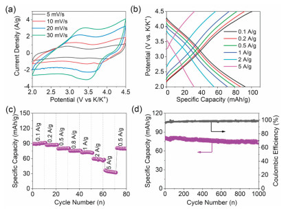
To study the electrode chemical performance of the asprepared ADPC electrode, a half-cell versus K metal was employed. Figs. 3a and b show the cyclic voltammetry (CV) and galvanostatic charging/discharging curves of ADPC-8 electrode with in a working potential range from 3.0 V to 4.5 V (vs. K/K+), respectively. The CV curves are quasi-rectangular in shape without any redox peak and the charging/discharging curves are nearly straight lines, suggesting a typical capacitive behavior. Fig. 3c shows the specific capacities of ADPC-8 electrode as a function of current density. The ADPC-8 electrode shows a high specific capacity of 91.3 mA h/g (131.5 F/g) at a current density of 0.1 A/g. Even at a large current density of 5 A/g, the specific capacity of ADPC-8 remains at 32.2 mAh/g (46.4 F/g). The ADPC-8 electrode shows better capacitive performance as compared to other ADPC electrodes (Fig. S4 in Supporting information), which is associated to its high surface area and optimal pore size-distribution. Furthermore, the capacitive performance of ADPC-8 electrode is highly comparable to commercial AC and other porous carbons in potassium-ion based organic electrolytes (Table S2 in Supporting information) [3, 19-23]. APDC-8 still preserves 72.9 mAh/g (91.2% of initial cycle value) after 1000 cycle span under a current density of 0.5 A/g, with a high columbic efficiency close to 98.5% (Fig. 3d).
Hard carbon is very promising as the negative material for potassium ion batteries or capacitors because of its low cost and environmental benignity [24, 25]. However, its relatively low K+ storage and sluggish kinetics impede its wide use. Recently, heteroatoms doping was demonstrated to be an efficient strategy for improving the electrochemical performance of hard carbon through surface and bulk functionalization [25]. Here, N, P codoped carbon was synthesized by oxidative polymerization of aniline and phytic acid, followed by pyrolysis under 1000 ℃ [26]. XRD of N, P co-doped carbon (Fig. S5 in Supporting information) only shows two broad diffraction peaks at 22° and 43°, suggesting the amorphous and defective nature. N, P co-doped carbon shows the rod-like structure with a diameter of ~100 nm and a length of ~1 μm (Fig. S6a in Supporting information). X-ray photoelectron spectroscopy (XPS, Fig. S6b in Supporting information) confirms the existence of C, O, N and P in N, P co-doped carbon. The contents of C, O, N and P atoms are 85.81, 8.44, 3.86 and 1.89 at%, respectively. The as-prepared N, P co-doped carbon as the anode is evaluated by a half-cell versus K metal. The first five galvanostatic discharge/charge curves of N, P co-doped carbon within a potential working range of 0.01-3 V (vs. K+/K) at 0.05 A/g are shown in Fig. S6c (Supporting information). The first discharge/charge capabilities of N, P co-doped carbon are calculated to 940 and 295 mAh/g, respectively, corresponding to an initial columbic efficiency of 31.3%. The low columbic efficiency for N, P co-doped carbon may stem from the synergistic effect of the formation of solid electrolyte interface or irreversible reactions between the electrolyte and surface functional groups [3, 25, 26]. Fig. S6d (Supporting information) shows that the reversible discharge capacities of N, P co-doped carbon are 319, 206, 163, 118, 104, 95, 78 and 47 mAh/g at the current densities of 0.05, 0.1, 0.2, 0.5, 0.8, 1, 2 and 5 A/g, respectively. Furthermore, N, P co-doped carbon has the good cycling stability with a capacity retention of ~71% after 1000 cycles under a current density of 1 A/g with a columbic efficiency around 100% (Fig. S7 in Supporting information). These results suggest that N, P co-doped carbon possesses the high specific capacity, high rate capability and good cycling stability, which make it a good candidate for anode in KICs.
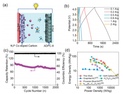
To further demonstrate the potential of ADPC in KICs, a prototype full cell was fabricated by using ADPC as the capacitive-type cathode and N, P co-doped carbon as the battery-like anode in KPF6 based organic electrolyte, as illustrated in Fig. 4a. The mass ratio of anode and cathode active materials was optimized to 1:1 with a consideration of the electrochemical performance of as-fabricated KICs (Fig. S8 in Supporting information). From the operating potential range of ADPC (2.0–4.5 V vs. K/K+) and N, P co-doped carbon (0.01-3 V vs. K/K+), a working voltage of the assemble KIC over 4.5 V is theoretically possible. To avoid the oxidative decomposition of electrolytes or other side reactions [12, 27], the working potential window of KICs was controlled between 1 V and 4.2 V. Fig. S9 (Supporting information) and Fig. 4b show the quasi-rectangular CVs and the symmetric linear charge/discharge curves, respectively, indicating a typical capacitive behavior for as-assembled N, P co-doped carbon//ADPC KIC. The N, P co-doped carbon//ADPC KIC also exhibits an acceptable cycle stability with a capacity retention of 75.6% after 2000 cycles at a high current density of 1 A/g with a high columbic efficiency of ~100% during cycling test (Fig. 4c). The energy and power densities of the as-fabricated KIC can be evaluated from the galvanostatic charge/discharge curves and are plotted in Fig. 4d. The optimized N, P co-doped carbon//ADPC KIC can deliver a high energy density of 72 Wh/kg at a power density of 257 W/kg. Even at a high-power density of 5220 W/kg, this KIC still provides an energy density of 18.5 Wh/kg. The energy and power performance of this KIC is compared favorably with state-of-theart KICs or sodium/lithium ion capacitors in the literature (Table S2) [6, 22, 28-37].
In summary, we report a one-step strategy to synthesize porous carbon-ADPC from the Aldol reaction product of acetone with KOH. The as-synthesized porous carbon has the narrow pore size distribution of 1-3 nm, a large nitrogen BET SSA of 2947 m2/g and a large pore volume of 1.45 cm3/g. Such porous carbon electrode was demonstrated to have the high specific capacity and high rate capability. It can deliver a high specific capacity of 91.3 mAh/g (131.5 F/g) at a current density of 0.1 A/g and 32.2 mAh/g (46.4 F/g) at a high rate of 5 A/g. By further coupling this porous carbon cathode and N, P co-doped carbon anode, a high-performance KIC was successfully constructed. This hybrid cell exhibits a large energy density of 72 Wh/kg and a high-power density of 5220 W/kg. Thus, our work suggests that this is simple and effective method to produce porous carbon with high surface area and large specific capacity, which can be considered as promising candidate of electrode materials for commercial supercapacitors and ionic capacitors.
The authors declare that they have no known competing financial interests or personal relationships that could have appeared to influence the work reported in this paper.
This work was supported by National Natural Science Foundation of China (No. 51902188) and Natural Science Foundation of Jiangsu Province (No. BK20190207).
J. Ding, W. Hu, E. Paek, D. Mitlin, Chem. Rev. 1118(2018) 6457-6498.
H. Wang, C. Zhu, D. Chao, et al., Adv. Mater. 29(2017) 1702093. doi: 10.1002/adma.201702093
J. Chen, B. Yang, H. Hou, et al., Adv. Energy Mater. 9(2019) 1803894. doi: 10.1002/aenm.201803894
H.D. Yoo, S.D. Han, R.D. Bayliss, et al., ACS Appl. Mater. Interfaces 8(2016) 30853-30862. doi: 10.1021/acsami.6b08367
L. Dong, W. Yang, W. Yang, et al., J. Mater. Chem. A 7(2019) 13810-13832. doi: 10.1039/C9TA02678A
L. Fan, K. Lin, J. Wang, et al., Adv. Mater. 30(2018) 1800804. doi: 10.1002/adma.201800804
H. Kim, J.C. Kim, M. Bianchini, et al., Adv. Energy Mater. 7(2017) 1702384.
L. Zhang, X. Yang, F. Zhang, et al., J. Am. Chem. Soc. 135(2013) 5921-5929. doi: 10.1021/ja402552h
B. Anothumakkool, S. Wiemers-Meyer, D. Guyomard, et al., Adv. Energy Mater. 9(2019) 1900078. doi: 10.1002/aenm.201900078
S. Wang, R. Wang, Y. Zhang, et al., J. Power Sources 379(2018) 33-40. doi: 10.1016/j.jpowsour.2018.01.019
M.D. Stoller, S. Murali, N. Quarles, et al., Phys. Chem. Chem. Phys. 14(2012) 3388-3391. doi: 10.1039/c2cp00017b
R. Wang, D. Jin, Y. Zhang, et al., J. Mater. Chem. A 5(2017) 292-302. doi: 10.1039/C6TA09143A
B. Li, F. Dai, Q. Xiao, et al., Energy Environ. Sci. 9(2016) 102-106. doi: 10.1039/C5EE03149D
H. Hou, C.E. Banks, M. Jing, et al., Adv. Mater. 27(2015) 7861-7866. doi: 10.1002/adma.201503816
J. Ding, H. Wang, Z. Li, et al., Energy Environ. Sci. 8(2015) 941-955. doi: 10.1039/C4EE02986K
M.A. Pimenta, G. Dresselhaus, M.S. Dresselhaus, et al., Phys. Chem. Chem. Phys. 9(2007) 1276-1291. doi: 10.1039/B613962K
L.G. Cançado, K. Takai, T. Enoki, et al., Appl. Phys. Lett. 88(2006) 163106. doi: 10.1063/1.2196057
F. Zhang, T.F. Zhang, X. Yang, et al., Energy Environ. Sci. 6(2013) 1623-1632. doi: 10.1039/c3ee40509e
Z. Zhang, M. Li, Y. Ca, et al., Adv. Funct. Mater. 28(2018) 1802684. doi: 10.1002/adfm.201802684
D. Qiu, J. Guan, M. Li, et al., Adv. Funct. Mater. 29(2019) 1903496. doi: 10.1002/adfm.201903496
Y. Cui, W. Liu, X. Wang, et al., ACS Nano 13(2019) 11582-11592. doi: 10.1021/acsnano.9b05284
S. Dong, Z. Li, Z. Xing, et al., ACS Appl. Mater. Interfaces 10(2018) 15542-15547. doi: 10.1021/acsami.7b15314
B. Yang, J. Chen, L. Liu, et al., Energy Storage Mater. 10(2019) 522-529.
Y. Liu, H. Dai, L. Wu, et al., Adv. Energy Mater. 9(2019) 1901379. doi: 10.1002/aenm.201901379
Y. Qian, S. Jiang, Y. Li, et al., Adv. Energy Mater. 9(2019) 1901676. doi: 10.1002/aenm.201901676
J. Zhang, Z. Zhao, Z. Xia, L. Dai, Nat. Nanotechnol. 10(2015) 444-452. doi: 10.1038/nnano.2015.48
S.R. Sivakkumar, A.G. Pandolfo, Electrochim. Acta 65(2012) 280-287. doi: 10.1016/j.electacta.2012.01.076
A.Le. Comte, Y. Reynier, C. Vincens, et al., J. Power Sources 363(2017) 34-43. doi: 10.1016/j.jpowsour.2017.07.005
L. Zhou, M. Zhang, Y. Wang, et al., Electrochim. Acta 232(2017) 106-113. doi: 10.1016/j.electacta.2017.02.096
H.V. Ramasama, B. Senthilkumar, P. Barpand, Y.S. Lee, Chem. Eng. J. 368(2019) 235-243. doi: 10.1016/j.cej.2019.02.172
C. Li, X. Zhang, K. Wang, et al., Chin. Chem. Lett. 31(2020) 1009-1013. doi: 10.1016/j.cclet.2019.09.056
C. Li, X. Zhang, K. Wang, et al., Carbon 140(2018) 237-248. doi: 10.1016/j.carbon.2018.08.044
C. Li, X. Zhang, K. Wang, et al., J. Power Sources 400(2018) 468-477. doi: 10.1016/j.jpowsour.2018.08.013
R. Wang, S. Wang, Y. Zhang, et al., Nanoscale 10(2018) 11165-11175. doi: 10.1039/C8NR02620C
C. Li, X. Zhang, C. Sun, et al., J. Phys. D Appl. Phys. 52(2019) 143001. doi: 10.1088/1361-6463/aaff3a
X. Hu, Y. Liu, J. Chen, et al., Adv. Energy Mater. 9(2019) 1901533. doi: 10.1002/aenm.201901533
B. Yang, J. Chen, H. Li, et al., J. Mater. Chem. A 7(2019) 9247-9252. doi: 10.1039/C9TA01653H

Figure 1 (a) Schematic illustration of the synthesis of ADPC, (b) and (c) SEM images of ADPC-8.

Figure 2 Structural characterization of ADPC-8: (a) XRD pattern, (b) Raman spectra, (c) Nitrogen adsorption-desorption isotherm curve, (d) pore-size distributions curve.

Figure 3 Electrochemical characterization of ADPC-8 electrode: (a) CVs, (b) galvanostatic charging/discharging curves, (c) Rate capability at various current densities ranging from 0.1 A/g to 5 A/g, (d) Cycle stability for about 1000 cycles at a current density of 0.5 A/g.

Figure 4 Electrochemical performance of N, P co-doped carbon//ADPC KICs: (a) schematic illustration of this KIC, (b) galvanostatic charge/discharge profiles, (c) cycle stability at a current density of 1 A/g with a high columbic efficiency (close to 100%), (d) Ragone plots of N, P co-doped carbon//ADPC KIC and other potassium-ion based hybrid capacitors.

 扫一扫看文章

扫一扫关注我们
 DownLoad:
 下载:
下载: