
Figure 1.
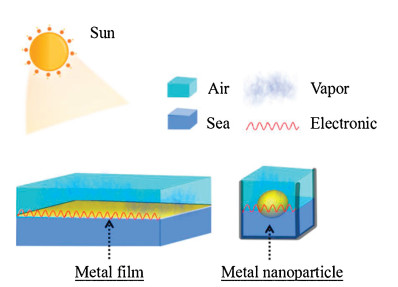
Two types of plasmonic models of metal-based materials in solar vapor generation: surface plasmonic polaritons (left); localized surface plasmonic (right) [5].

With the rapid development for the economics of human society, many organizations worldwide have an insistent demand for safe drinking water [1-4]. There is a huge population worldwide using improved drinking water, this task requires huge expenses each year to collect enough drinking water due to traditional application of water treatment technology (i.e., membrane filtration and thermal distillation) has high cost and low efficiency [5, 6]. Unfortunately, some regions of Asia and Africa are unable to obtain adequate safe drinking water for regional economy and technology.
Along with the rapid development of nanomaterials and nanotechnology, photothermal conversion was applied to many fields, including the production of safe drinking water [7-12], high temperature steam sterilization [13], solar water heaters [14-17], recycling of precious metals [18], oil and water separation [19, 20], CO2 capture [21], etc. Therein, solar-driven safe drinking water production technology via a simple photothermal conversion process shows superior features: green, sustainable, convenient and low-cost solar energy; no other contaminating byproducts [22]. Although water resources on the earth are abundant currently, most of them are seawater with high salt concentration, which is not suitable for human direct drinking. About 71% of the Earth's surface area is covered by seawater, it is considered as the excellent candidate for safe drinking water [23, 24]. Seawater contains a lot of Na+, Cl- and other numerous elements, a mass of which are required by the human body. However, the concentration of various elements in seawater is too high, far exceeding the hygienic standard of drinking water. If it is consumed in large quantities, it will cause some elements to enter the human body in excess, affecting the normal physiological functions of the human body, and serious poisoning [25]. People who drink seawater not only cannot supplement the water that the human body needs, but the dehydration accelerates and eventually causes death. Treating seawater in an inexpensive and efficient way to access safe drinking water is an important means of solving this series of problems.
Fortunately, photothermal vapor generation device (PVGD) gains the enough attention of researchers and merchant in recent years. The significant highlights of PVGD are that can still maintain high optical-thermal evaporation efficiency without optical focusing (i.e., the absorber under the radiation of one sun, 1 kW/m2). Solar evaporation captures clean solar and zero greenhouse gas emissions, an attractive advantage in addressing clean energy demand, water scarcity and global warming issues. However, in solar-powered evaporation systems without optical focusing, many challenges are still encountered. Some typical problems are including but not limited to low energy conversion efficiency normally being explored by researchers.
In the process of exploring the preparation of solar absorber materials, metal elements are an important component of the composition of matter [26]. According the latest periodic table of elements, it is found that among the 118 elements, 24 non-metallic elements are removed, and the rest are metal elements. This is enough to illustrate the proportion of metal elements that are important in scientific research and daily life. Meantime, metal elements have also played an active role in the development of the PVGD system. Here, the metal-based materials mainly refer to PVGD contains plasmonic metal nano materials (Au, Ag, Pt, Al, Pd, Ge nanoparticles, etc.) [27-40] or porous metal/alloy materials (porous Al, foamed Ni, foamed Cu, foamed Ti, etc.) [28, 41-54] or metal element composite (CuFeMnO4, TiAlOx, Cu2SnSe3, CuFeSe2, etc.) [25, 55-66]. Compared with other photothermal conversion materials (such as carbon-based materials, organic polymer materials), metal-based materials possess following advantages: (ⅰ) Nanoscale metal materials are easy to control their optical properties (can achieve near-perfect optical absorption). Ordinary carbon-based materials such as biomass carbon materials tend to have 5%-10% reflection [2]. (ⅱ) Metal-based materials through structural regulation were used to achieve some specific functions of PVGD (multifunctional implementation, rapid thermal response, corrosion resistance, recyclability, etc.). (ⅲ) Through the doping of metal-based materials, heat loss (especially thermal radiation loss) can be effectively reduced [17]. Carbon-based materials and organic polymer materials are difficult to effectively regulate heat radiation loss. (ⅳ) Metal-based materials tend to have good mechanical properties and protect the entire device. This is more conducive to long-term preservation of equipment in the marine environment.
In this review, we introduce the basic mechanism of photothermal conversion for metal-based materials in the section 2. We analyze the influencing factors of PVGD from the perspectives of environment, materials and systems, and the appropriate criteria for evaluating its performance. This discussion plays an important role about the analyzing of energy balance in entire photothermal conversion process. For desalination technology, system design (volumetric or interface), module configuration (powder or bulk), and energy recovery (freshwater recycling process) are all issues that should be considered. Then we explore state-of-the-art developments in metal-based materials to efficiency localized evaporation in volumetric solar distillation system and interfacial solar distillation system which is achieved by optical adjustment. And next section, the importance of thermal adjustment in interfacial system was introduced emphasized, especially the heat radiation loss suppressed by the application of selective absorber surface. These two sections are the core of the entire review and are also characterized by the intrinsic of metal-based materials. In the end, we make a conclusion of the entire review, as well as a detailed statement of the challenges of metal-based materials in future.
Here we will separately discuss the photothermal conversion mechanism of three types of metal-based absorbers (plasmonic metal nanomaterials, porous metal/alloy materials, metal element composite). Three different metal-based photothermal conversion materials have many differences in optical absorption and heat transfer.
The photothermal conversion mechanism of plasmonic metal nanomaterials is plasmonic effect. The plasmonic noble metal can achieve precise absorption spectrum cutting by utilizing the current diversified structural control means (i.e., nanotechnology). The plasmonic effect of metal nanomaterials is divided into two modes: Surface plasmonic polaritons effect and localized surface plasmonic resonance effect. As a structure-driven light absorption mode, plasmonic has a large difference from the absorption properties of the bulk material. Changes in size, configuration, and background dielectric will cause the formants to move in a directional manner, and the particle configuration will also affect the absorption cross section. The plasmonic effect of metal nanomaterials also greatly expands the types and applications of materials, such as negative refractive index materials, optical stealth cloaks and photothermal conversion devices [67]. Here we mainly introduce two types of plasmonic models for the application of metal-based solar absorbers in interface desalination systems (i.e., the absorber is located at the gas-liquid interface) (Fig. 1). The physical character of the plasmonic on the metal surface is a collective oscillating electromagnetic mode in which the free electrons on the conduction band near the Fermi level are excited by the external electromagnetic field, which is usually regarded as a surface element excitation. When the metal film is irradiated by sunlight, the free electrons on the surface of the film are excited by the electromagnetic field to form a resonance, thereby realizing efficient energy transfer. The metal film transfers the light energy to the heat energy, and the heat energy is applied to the process of seawater evaporation. Similar to the surface plasmonic polaritons phenomenon, localized surface plasmonic is derived from the coupling of the collective oscillation of free electrons on the surface of metal and sunlight. Localized surface plasmonic significantly increase the absorption cross section of the material. Taking metal silver nanoparticles as an example, the light field enhancement on the surface of a single nanoparticle can be up to 103 times, thereby achieving photo-thermal steam generation. The calculating extinction cross-section formula of metal nanospheres in Mie theory can describe localized surface plasmonic effectively.
|
|
(1) |
where Cext is the extinction cross section, R is the radius of the metal nanospheres, and εm is the relative dielectric constant of the medium surrounding the metal nanosphere. So the interaction between a metal nanoparticle and light depends largely on its dielectric properties (εr and εi) while keeping these two values (R and εm) unchanged.
From an engineering perspective, when some other factors (temperature, humidity, pressure, excitation wavelength, etc.) are fixed values, the material properties of the plasma structure are the key factors affecting optical absorption.
In other words, when the value outside the square brackets on the right side of the formula is a constant value, the value of the denominator of the formula in square brackets tends to zero, and Cext is oriented to infinity. The condition of plasmonic resonance is that when the extinction cross section is infinite, the optical absorption and scattering at this particular frequency is very powerful.
In order to achieve a strong photothermal conversion, that is, localized surface plasmonic polarization, the value of (εr-2εm) must be close to zero. This condition is difficult to achieve for standard dielectric and non-metallic that typically have εr values ranging from 1 to 50, which further demonstrates the superiority of optical adjustment of metal-based absorbers.
In Eq. (1), it can be seen that when εi is close to zero, it is easy to achieve strong resonance between the incident electromagnetic wave and the metal surface, and this condition can only be satisfied by the metal material. Metal nanoparticles achieve efficient photothermal conversion because of strong ohmic losses during their electronic resonance. Nanoparticles can completely contact the working fluid, which is more conducive to heat transfer.
As for the role and effect of the porous metal template in solar steam generation system, see section 3.2. And the photothermal conversion mechanism of metal element composite is diverse, which is also the charm of metal-based absorbing materials. Metal element complexes often represent that they are not limited to one metal element, and involve some inorganic semiconductor materials, general metal compound materials, etc. In view of the fact that it is not limited to the participation of one metal element, the recombination and separation of electrons and holes can be achieved simultaneously in the entire system. Based on the characteristics of this rich metal composite material [68], the geometrical operation, compositional complexity and structural diversity of this material can be used to improve its efficiency from multiple angles [69]. (For example, directly improve the efficiency of solar energy utilization, and indirectly realize the efficient useof the system throughmulti-functional composite). We can use nanotechnology to change the material structure design to improve its photothermal conversion capability. The photothermal conversion mechanism of these materials often needs to be analyzed according to the actual doping conditions [66, 70, 71].
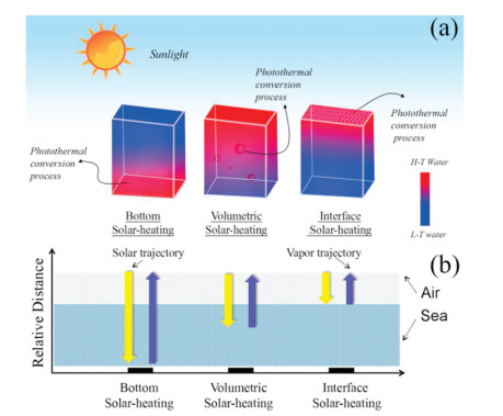
As shown in Fig. 2a, the metal-based system structure of solardriven steam generation having three modes which is mainly and widely recognized currently [3]. In general, the major difference between the three models is that the location where the photothermal conversion process occurs is differentiated, resulting in different efficiency of photothermal conversion. Therefore, the position of the solar absorber is in most cases the position of photothermal conversion in the solar-driven steam generation system. The most straightforward way we can adjust the three heating methods by adjusting the position of the solar absorber. For the position of the absorber, we can fix the position by adjusting the surface wettability, buoyancy, density or direct mechanical action (such as the absorber material is fixed on a polypropylene foam) of the material [2, 72].
The bottom solar heating of metal-based PVGD is similar to the way in which the heat energy generated by the direct combustion of coal, natural gas, and biomass materials in the factory to boil the bulk water to produce steam. This method has a low utilization rate of heat energy, and most of the energy consumption is in the sensible heat of evaporation. Usually this method uses a high-value lens to focus the sun to generate steam, so this traditional solar heating method does not receive enough attention [5, 73]. For the bottom-solar heating method, in addition to the low efficiency of solar energy utilization, material recovery, long-term service is also a huge problem compared with volumetric solar heating and interface solar heating of metal-based PVGD.
With the rapid development of nanomaterials and nanotechnology, nanoparticles are dispersed in bulk water (called nanofluid) [74], and under the irradiation of sunlight, the seawater desalination can be produced more efficiently. Compared to suspensions with micron or millimeter-sized particles, nanofluids exhibit better stability, rheology, thermal and optical properties and therefore have broader practical application potentials such as desalination, heating and cooling, hyperthermia, etc. The heat energy is generated by the resonance between sunlight frequency and frequency of electron in noble metal nanoparticles. Currently, nanofluids improve solar-thermal evaporation efficiency by controlling the shape, aggregation, size, structure and dopant of plasmonic nanoparticles. However, the collection safe-drinking water efficiency in volumetric solar heating of metal-based PVGD is still relatively low. There is a large amount of heat energy that is transmitted to the surroundings by heat conduction. And the resulting steam motion process is also complex and controversial.
Immediately, people quickly realized that the heat transfer loss should be minimized, and reducing the heating of undesired water can improve the evaporation efficiency. In 2011, Wang's group proposed a new strategy to improve solar-driven steam generation efficiency by used floating magnetic nanoparticles Fe3O4/C [74], and the biggest advantage of this method is to shorten the trajectory of light running and steam trajectory, and also increase the convenience of material recycling. As show in Fig. 2b, the relative distance for the trajectory of sunlight (yellow arrow in Fig. 2b) and the trajectory of the steam motion (blue arrow in Fig. 2b) is quite different in the three modes.
In the process of solar steam generation, three heat energy transfer channels are heat conduction, heat convection, and heat radiation. The relative distance of the sunlight and the vapor trajectory has an important effect on the light absorption and the change in the magnitude of the three heat losses. The interface system can be directly contacted with the metal nanoparticles more effectively with the medium of sunlight only through the air, which greatly reduces the energy loss, and the steam can also be directly released into the air, avoiding movement of the steam in bulk water. Thus, avoids in-situ cooling of steam and increases the amount of condensate that can be collected. Further, Deng's team, inspired by skin sweating and plant transpiration, achieved localized evaporation of the gold nanofilm at the gas-liquid interface, further reducing heat transfer losses [77]. Water is transported to the surface by the capillary action generated by the porous structure of the film, and the surface water then absorbs the intense local heat generated by the gold nanofilm to form effective seawater desalination. Then, a low thermal conductivity capillary material such as dust-free paper is used as a thermal insulation layer to support the plasmonic metal nanomaterial to form a more efficient evaporation. Gold films (non-discrete metal particles) deposited on dust-free paper have relatively high absorption efficiencies over flat gold or gold particle nanofluids because of the high roughness of the surface of the dust-free paper. This research provides a great reference for the application route of PVGD.
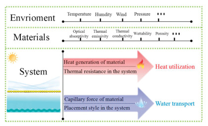
The current research on interfacial solar-driven seawater desalination is hot. However, the reported evaporation efficiency is not directly comparable owing to the lack of standardized measurements and some tiny important factors are easy to ignore. Therefore, here we summarize some factors that have an important impact on the evaporation efficiency of PVGD from the environment, materials, and systems (Fig. 3).
In the case where all experimental operating conditions are accurately determined (including temperature of solar absorber surface, vapor temperature and power density of solar illumination), the expression of evaporation capability of PVGD can also be qualitatively analyzed as follows:
|
|
(2) |
Notably, this formula is only an empirical formula that qualitatively considers the factors affecting the evaporation capability of the entire PVGD. It does not mean that each factor is numerically related. Here, E.C. refers to the evaporation capability of this metal-based PVGD; K is a environment constant, determined by the temperature, humidity, wind, pressure of the environment. According to previous articles, different work environments often have a significant impact on evaporation efficiency, so these parameters remain constant for a unified PVGD [1-4]; σi is an intrinsic factor determined by the nature of material, including wettability, porosity, thermal conductivity, optical absorptivity, and thermal emissivity, etc. These characteristics are critical to the energy analysis and simulation of the entire metal-based PVGD; σh is a heat utilization factor, which is mainly determined by the photothermal conversion capability of the material and the total thermal resistance of the system. σW is the water transport factor, which is determined by the capillary force of the material and the way the material in the system is in contact with water. This reminds us that we cannot directly judge the water transport capacity (or capillary driving force) of PVGD by the materials surface wettability and porosity of the material. Understanding completely the transport process behavior of water molecules in confined spaces is related to material structure and properties typically used for structural characterizations such as pore dimension, surface texture, and tortuosity.
In our previous research, we have explored different ways of stacking uniform materials from system heat utilization and system water transport [2, 85].
After reasonable testing and a statement of some important factors, we should first perform an energy analysis based on the formula:
|
|
(3) |
Among them, 
Its energy conversion efficiency (η) is defined as:
|
|
(4) |
Here,
After considering the factors of the experiment and the energy analysis during the evaporation process, it is very convenient for comparing different research experiments.
The localized evaporation achieved by efficient absorption of sunlight and less heat energy loss has been the goal of solar desalination (detailed in section 2.2). Below we will introduce the localized evaporation achieved by adjusting the absorption material (or combining some other materials) in volumetric solar heating and interface solar heating respectively.
As shown in Fig. 4a, the volumetric solar heating of metal-based PVGD has a significant improvement in energy utilization efficiency compared with bottom-solar heating. A liquid-air phase change localized around the individual nanoparticles (i.e., a localized evaporation formed around this absorber) can be used to explain this process. However, this explanation does not match the experimental results of individual particles. Halas's group found that simultaneous absorption and scattering of sunlight by particles in solution can form a highly localized evaporation. Localized light absorption and heat transfer, resulting in a temperature difference of ~25 ℃ at the top and bottom of the water body, the photothermal conversion is highly limited to ~0.5 mm deep water surface [75].
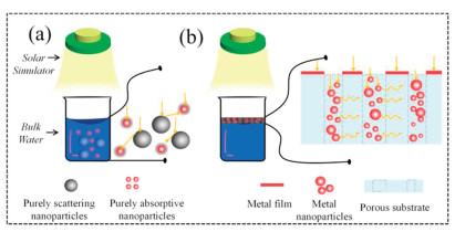
Base on high concentration of metal nanoparticles, with natural thermal locality, spontaneously inhibits heating of the entire water body. The high extinction coefficient of metal leads to a smaller skin depth, while the high particle concentration of metal nanoparticles further increases the thermal locality and achieves a stronger, more concentrated hot spot. Further research, Deng's group use mixture (purely light absorptive plasmonic nanoparticles and purely scattering particles) to confine the incident light at the vicinity of the gas-liquid interface and convert light to heat. They are no longer limited to the use of the same nanoparticle as the center of absorption and scattering, and propose the use of mixed particles (pure absorbing particles and pure scattering particles) (Fig. 4b). This separation-enabled system allows us to independently adjust light absorption and light scattering, and to explore optimal localized evaporation solutions in volumetric solar heating of metal-based PVGD [76].
The physical properties behind LSPR are enhanced absorption and scattering. These two processes will result in a highly enhanced electric field near the nanoparticles (near field) and produce surface-enhanced spectroscopy. Therefore, we can hopefully achieve a high degree of localized heating by rationally adjusting the absorption and scattering centers for metal-based nanoparticles.
As for the localized evaporation for interface solar heating of metal-based PVGD, gold film seems to have achieved higher evaporation efficiency (detailed in section 2.2) via floating on the air-liquid interfacial.
However, further we can assemble gold nanoparticles into different types of substrate materials by immersion or deposition methods, such as dust-free paper, wood, porous aluminum sheets, and the like. The thickness (dimension), porosity, pore size, mechanical (flexibility and stiffness), surface roughness energy of these templates (Table 1) have a significant effect on the optical adjustment of the entire device.
The assembly of the porous substrate seems to have a very high promoting effect on the interfacial evaporation localized evaporation. Compared with 2D template (such as paper) assembly, the 3D assembly structure not only has advantages in multiple scattering on the system, but also supports more plasmonic modes. The Zhu's group used the porous aluminum anodic template (AAO) to carry out three-dimensional self-assembly of gold nanoparticles to prepare a near-perfect absorber with an absorption rate of up to 99% [28]. Through the hybridization of a large number of plasmonic resonance modes between the particles, the absorber overcomes the narrow band absorption characteristics of the single metal nanoparticles and extends the absorption band to the mid-infrared band. AAO can also assist in building a refractive index that matches the air, effectively suppressing reflection by reducing the interface impedance. Thus, effective localized partial evaporation can overcome the inherent narrow band absorption of precious metals by two methods: 1) Trimming and fine-tuning the shape and size of plasmonic nanoparticles; and 2) Nanoparticles are combined with other 2D or 3D structural materials. The nanoporous template also provides impedance matching to effectively reduce reflection and couple into the optical mode reduction and coupling to the optical modes. Hu's team used a wood substrate with a larger aperture to achieve a wider sunlight absorption boundary [29].
Thermal energy loss in photothermal conversion system mainly has heat conduction, heat convection, heat radiation loss. Here the thermal adjustment refers to absorber has high absorption rate in the band 0.25-2.5 μm and can have low emissivity in the band 2.5-25 μm. The ideal metal-based solar harvesting device has high solar absorption and low thermal radiance.
In view of the potential of nanoparticles to improve the radiation properties of liquids, the thermodynamic control of nanofluids is not elaborated here. This section focuses on whether interface solar heating of metal-based PVGD has a selective surface.
Tabor creating a study of spectrally selective solar collector absorber surface 1955. The first type constitutes a low emissivity metal substrate covered by a thin surface layer, such as black chrome, black nickel, copper oxide, which is opaque in the visible region but substantially transparent in the infrared region. The second type consists of a metal system with low emissivity, exhibiting high absorption in the visible spectrum due to color or subdivision structure. In the next few years, several mechanisms have been employed to develop spectrally selective surfaces. In other words, the ideal spectrally selective absorber has zero reflectivity in the visible region and high reflectivity in the infrared region [78-81].
As shown in Table 2, a summary of some important parameters of current metal-based solar harvesting device with non-selective absorber surface.
 DownLoad:
CSV
DownLoad:
CSV

|
The current application of this type of absorber is generally summarized in the following aspect: (1) Materials diversity, which can be prepared in combination with a variety of materials, without a clear preparation sequence requirement; (2) The diversity of preparation methods, and there is no absolutely strict requirement for the preparation environment; (3) Different structures possessed by materials can promote different light absorption and have extensive research space.
This range of conveniences provides great follow-up for the applicability of non-selective surface of metal-based absorber application. As shown in Fig. 5, the non-selective surface tends to exist in the following two cases: (ⅰ) having a high absorption rate and a high thermal emissivity; (ⅱ) having a low absorption rate and a low thermal emissivity. Therefore, when the non-selective surface is not considered to control the thermal emissivity, it can achieve a higher absorption rate in the solar spectrum. Moreover, when the thermal emissivity is not considered, the material selection can be combined with some materials with high thermal emissivity such as carbonized wood, which has low thermal conductivity and is beneficial to reduce heat conduction loss, which is the charm of nonselective absorption surface of metal-based device.
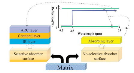
However, in pursuit of high solar absorption rate, the loss of thermal energy is also an indispensable link. Thermal energy is mainly transmitted in three forms: heat conduction, heat convection, and heat radiation. Among them, heat radiation loss is an important heat loss path and is relatively difficult to control. This requires the material to maintain a high absorption (0.2-2.5 μm) while maintaining required low emissivity (2.5-25 μm). This means that the entire device has a large difference in reflectivity between the two bands. Metal-based photothermal conversion materials have an overwhelming advantage in possessing high light absorption while maintaining low thermal emissivity.
At present, Jian Huang et al. prepared C@TiO2 film formed on the Cu substrate for solar steam and achieved good results [82]. Through the combination of experiments and theoretical analysis, the three components have the following effects. The carbon material mainly enhances the optical absorption rate of the device in the ultraviolet visible region, and the copper matrix material reduces the emissivity in the infrared region. Titanium dioxide has the function of not only enhance absorbing more energy of amorphous carbon, but also protecting the composite film during photothermal conversion process, so that its infrared emissivity is not degraded.
Selectively absorbing coatings are considered as a common selective surface for solar harvesting device due to its easy to adjust optical reflection. This type of equipment is a mixture of metal and ceramic, including three types of function layer: an anti-reflection coating (ARC) and an IR reflective base layer (either an intrinsically IR-reflecting substrate or an IR-reflective coating on a substrate), cermet-based coatings [83].
The anti-reflection coating (ARC) reduces solar reflection off the surface; the cermet provides selective absorption; and the IR reflector (typically Cu, Al, Mo, or other metals with low intrinsic emissivity) reduces radiation losses. The substrate is usually metal (to conduct heat well) or glass (for lower cost). Chen's team has commercialized a selective absorbing coating through large holes and assembled some other materials to achieve good desalinated seawater efficiency under natural light. Moreover, in order to prevent contamination and damage of the absorber by impurities, they creatively separate the selective absorber from the water surface, and by adjusting the heat radiation, superheated steam can be generated in a non-pressurized state [84].
In view of the high preparation requirements, complex material system, poor corrosion and so on, there are currently few studies on selective surfaces, and this aspect requires further exploration.
This review begins with a description of the basic concepts and evaluation criteria for metal-based solar harvesting devices, including plasmonic noble metals, porous metal templates, and metal composites. Then, the promotion effect of optical adjustment and thermal regulation of metal-based solar absorbers on solar desalination is highlighted. In the optical adjustment section, we mainly discuss how to achieve the efficient localized evaporation in the volumetric heating mode and the interface heating mode. In the thermal regulation section, it is mainly discussed that the selective absorption surface can effectively reduce the thermal radiation loss of the interface desalination device, and a common selective absorption surface of the spectral selective absorption coating is highlighted. Finally, we summarize the challenges and difficulties of metal-based solar desalination devices as follows:
(1) Metal-based materials are relatively expensive compared to conventional carbon materials, so we need to reduce the cost of solar harvesting equipment by reasonable doping. For example, using some biomass materials for compounding, we have studied and summarized this in our previous work [2, 85, 86].
(2) The evaporation efficiency of metal-based devices in different modes needs to be further improved to enable largescale use. This is an important issue in the design of solar harvesting devices.
(3) Metal-based devices need further exploration for salt corrosion and biological pollution of seawater. We have successfully prepared an Al-AlNxOy solar selective absorber coating that is significantly more resistant to corrosion than the commercial and laboratory coatings reported. After a 2000 h neutral salt spray test, the coating still exhibited a high absorption rate (0.924) and a low thermal emissivity (0.116) [15, 95].
(4) Solar selective absorber coatings need to be more deeply integrated with the field of solar desalination to prepare selective absorption surfaces that can specifically serve the desalination of solar water. The Chen's group used a commercial selective absorber coating to create complete foam with perforated, low thermal conductivity foam [84]. This research gave us great inspiration. Whether a selective absorber coating can be constructed on the porous material or a selective absorber coating can be deposited directly on some low thermal conductivity materials. From an industrial point of view, these studies are more conducive to their large-scale use.
This work is financially supported by the National Natural Science Foundation of China (Nos. 51562020 and 51575253).
W. Chen, S. Chen, T. Liang, et al., Nat. Nanotechnol. 13(2018) 345-350. doi: 10.1038/s41565-018-0067-5
Z. Li, C. Wang, J. Su, et al., Sol. RRL 3(2019) 1800206. doi: 10.1002/solr.201800206
P. Tao, G. Ni, C. Song, et al., Nat. Energy 3(2018) 1031-1041. doi: 10.1038/s41560-018-0260-7
H. Kou, Z. Liu, B. Zhu, et al., Desalination 462(2019) 29-38. doi: 10.1016/j.desal.2019.04.005
Z.Y. Deng, J.H. Zhou, L. Miao, et al., J. Mater. Chem. A 5(2017) 7691-7709. doi: 10.1039/C7TA01361B
S.V. Boriskina, A. Raza, T. Zhang, et al., MRS Bull. 44(2019) 59-66. doi: 10.1557/mrs.2018.325
Y. Bian, Q. Du, K. Tang, et al., Adv. Mater. Technol. 4(2018) 1800593.
B. Chen, H. Jiang, H. Liu, et al., 2D Mater. 6(2019) 035018. doi: 10.1088/2053-1583/ab15ac
P. Mu, W. Bai, Y. Fan, et al., J. Mater. Chem. A 7(2019) 9673-9679. doi: 10.1039/C8TA12243A
Z. Zhang, P. Mu, J. He, et al., ChemSusChem 12(2019) 426-433. doi: 10.1002/cssc.201802406
P. Mu, W. Bai, Z. Zhang, et al., J. Mater. Chem. A 6(2018) 18183-18190. doi: 10.1039/C8TA05698F
P. Mu, Z. Zhang, W. Bai, et al., Adv. Energy Mater. 9(2019) 1802158. doi: 10.1002/aenm.201802158
J. Li, M. Du, G. Lv, et al., Adv. Mater. 30(2018) e1805159. doi: 10.1002/adma.201805159
C. Wang, W. Cheng, P. Ma, R. Xia, X. Ling, J. Mater. Chem. A 5(2017) 2852-2860. doi: 10.1039/C6TA09460K
C. Wang, Z. Li, W. Wang, R. Xia, X. Ling, J. Mater. Chem. A (2019) 13080-13089.
W. Wang, H. Wen, S. Ling, et al., J. Mater. Chem. A 6(2018) 15690-15700. doi: 10.1039/C8TA05231J
W. Wang, H. Wen, J. Shi, et al., Sol. RRL 3(2019) 1900180. doi: 10.1002/solr.201900180
X. Li, W. Xu, M. Tang, et al., Proc. Natl. Acad. Sci. U. S. A.113(2016) 13953-13958. doi: 10.1073/pnas.1613031113
J. Chang, Y. Shi, M. Wu, et al., J. Mater. Chem. A 6(2018) 9192-9199. doi: 10.1039/C8TA00779A
M. Wu, Y. Shi, J. Chang, et al., Adv. Mater. Interfaces 5(2018) 1800412. doi: 10.1002/admi.201800412
V. Kashyap, R. Medhi, P. Irajizad, et al., Sustain. Energy Fuel. 3(2019) 272-279. doi: 10.1039/C8SE00546J
R. Li, P. Wang, Rational Design of Nextgeneration Nanomaterials and Nanodevices for Water Applications (Eds), 2020, pp. 1-12.
J.B. Zimmerman, J.R. Mihelcic, J. Smith, Environ. Sci. Technol. 42(2008) 4247-4254. doi: 10.1021/es0871457
G.N. Tiwari, H.N. Singh, R. Tripathi, Sol. Energy 75(2003) 367-373. doi: 10.1016/j.solener.2003.07.005
Y. Yang, H. Zhao, Z. Yin, et al., Mater. Horiz. 5(2018) 1143-1150. doi: 10.1039/C8MH00386F
P. Ma, Y. Sun, X. Zhang, J. Chen, et al., Energy Storage Mater. 23(2019) 159-167.
L. Zhou, Y.L. Tan, J.Y. Wang, et al., Nat. Photonics 10(2016) 393. doi: 10.1038/nphoton.2016.75
L. Zhou, Y. Tan, D. Ji, et al., Sci. Adv. 2(2016) e1501227. doi: 10.1126/sciadv.1501227
H.D. Kiriarachchi, F.S. Awad, et al., Shall, Nanoscale 10(2018) 18531-18539. doi: 10.1039/C8NR05916K
Y. Liu, Z. Liu, Q. Huang, et al., J. Mater. Chem. A 7(2019) 2581-2588. doi: 10.1039/C8TA10227A
Y. Liu, S. Yu, R. Feng, et al., Adv. Mater. 27(2015) 2768-2774. doi: 10.1002/adma.201500135
L. Tian, J. Luan, K.K. Liu, et al., Nano Lett. 16(2016) 609-616. doi: 10.1021/acs.nanolett.5b04320
H. Wang, L. Miao, S. Tanemura, Sol. RRL 1(2017) 1600023. doi: 10.1002/solr.201600023
T. Wu, H. Li, M. Xie, et al., Mater. Today Energy 12(2019) 129-135. doi: 10.1016/j.mtener.2018.12.008
Y. Yang, X. Yang, L. Fu, et al., ACS Energy Lett. 3(2018) 1165-1171. doi: 10.1021/acsenergylett.8b00433
L. Yi, S. Ci, S. Luo, et al., Nano Energy 41(2017) 600-608. doi: 10.1016/j.nanoen.2017.09.042
L. Zhang, J. Xing, X. Wen, et al., Nanoscale 9(2017) 12843-12849. doi: 10.1039/C7NR05149B
X. Lin, M. Yang, W. Hong, D. Yu, X. Chen, Front. Mater. 5(2018) 74. doi: 10.3389/fmats.2018.00074
M. Wang, P. Wang, J. Zhang, C. Li, Y. Jin, ChemSusChem 12(2019) 467-472. doi: 10.1002/cssc.201802485
G. Song, Y. Yuan, J. Liu, et al., Adv. Sustainable Syst. 3(2019) 1900003. doi: 10.1002/adsu.201900003
Z. Lin, Y. Tan, D. Ji, B. Zhu, et al., Sci. Adv. 2(2016) e1501227. doi: 10.1126/sciadv.1501227
H. Ren, M. Tang, B. Guan, et al., Adv. Mater. 29(2017) 1702590. doi: 10.1002/adma.201702590
S.M. Sajadi, N. Farokhnia, P. Irajizad, et al., J. Mater. Chem. A 4(2016) 4700-4705. doi: 10.1039/C6TA01205A
D. Wu, D. Qu, W. Jiang, et al., J. Mater. Chem. A 7(2019) 8485-8490. doi: 10.1039/C9TA00529C
L. Zhang, B. Tang, J. Wu, R. Li, P. Wang, Adv. Mater. 27(2015) 4889-4894. doi: 10.1002/adma.201502362
M. Zhu, Y. Li, F. Chen, et al., Adv. Energy Mater. 8(2018) 1701028. doi: 10.1002/aenm.201701028
K. Yin, S. Yang, J. Wu, et al., J. Mater. Chem. A 7(2019) 8361-8367. doi: 10.1039/C9TA00291J
S. Ma, W. Qarony, M.I. Hossain, C.T. Yip, Y.H. Tsang, Sol. Energy Mater. Sol. Cells 196(2019) 36-42. doi: 10.1016/j.solmat.2019.02.035
J. Yao, Z. Zheng, G. Yang, Nanoscale 10(2018) 2876-2886. doi: 10.1039/C7NR09229F
C. Chang, P. Tao, B. Fu, et al., ACS Omega 4(2019) 3546-3555. doi: 10.1021/acsomega.8b03573
Q. Ma, P. Yin, M. Zhao, et al., Adv. Mater. 31(2019) e1808249. doi: 10.1002/adma.201808249
M. Kaur, S. Ishii, S.L. Shinde, T. Nagao, Adv. Sustain. Syst. 3(2019) 1800112. doi: 10.1002/adsu.201800112
C. Wang, Y. Wang, X. Song, M. Huang, H. Jiang, Adv. Sustain. Syst. 3(2019) 1800108. doi: 10.1002/adsu.201800108
P. Ren, X. Yang, Sol. RRL 2(2018) 1700233. doi: 10.1002/solr.201700233
L. Yi, D. Qi, P. Shao, et al., Nanoscale 1(2019) 9958-9968.
L. Shi, Y. Shi, S. Zhuo, et al., Nano Energy 60(2019) 222-230. doi: 10.1016/j.nanoen.2019.03.039
H. Liu, C. Chen, H. Wen, et al., J. Mater. Chem. A 6(2018) 18839-18846. doi: 10.1039/C8TA05924A
X. Zhang, X. Wang, W.D. Wu, X.D. Chen, Z. Wu, J. Mater. Chem. A 7(2019) 6963-6971. doi: 10.1039/C8TA12290C
F. Zhang, Y. Li, X. Bai, et al., J. Mater. Chem. A 6(2018) 23263-23269. doi: 10.1039/C8TA08259F
M. Ye, J. Jia, Z. Wu, et al., Adv. Energy Mater. 7(2017) 1601811. doi: 10.1002/aenm.201601811
Y. Shi, R. Li, L. Shi, et al., Adv. Sustain. Syst. 2(2018) 1700145. doi: 10.1002/adsu.201700145
Q. Lu, Y. Yang, J. Feng, X. Wang, Sol. RRL 3(2019) 1800277. doi: 10.1002/solr.201800277
X.-Y. Wang, J. Xue, C. Ma, et al., J. Mater. Chem. A 7(2019) 16696-16703. doi: 10.1039/C9TA02210D
L. Zhao, Q. Yang, W. Guo, et al., ACS Appl. Mater. Interfaces 11(2019) 20820-20827. doi: 10.1021/acsami.9b04452
T.F. Chala, C.M. Wu, M.H. Chou, Z.L. Guo, ACS Appl. Mater. Interfaces 10(2018) 28955-28962. doi: 10.1021/acsami.8b07434
L. Zhu, L. Sun, H. Zhang, et al., Nano Energy 57(2019) 842-850. doi: 10.1016/j.nanoen.2018.12.058
M. Rycenga, C.M. Cobley, J. Zeng, et al., Chem. Rev. 111(2011) 3669-3712. doi: 10.1021/cr100275d
Z. Li, L. Sun, Y. Liu, et al., Environ. Sci. Nano 6(2019) 1507-1515. doi: 10.1039/C9EN00149B
Y. Liu, X. Li, W. Shen, et al., Small 15(2019) 1804737. doi: 10.1002/smll.201804737
Y.S. Jun, X. Wu, D. Ghim, et al., Acc. Chem. Res. 52(2019) 1215-1225.
C. Chen, Y. Kuang, L. Hu, Joule 3(2019) 683-718. doi: 10.1016/j.joule.2018.12.023
N. Xu, X.Z. Hu, W.C. Xu, et al., Adv. Mater. 29(2017) 1606762. doi: 10.1002/adma.201606762
A. Raza, J.Y. Lu, S. Alzaim, H. Li, T. Zhang, Energies 11(2018) 253. doi: 10.3390/en11010253
Y. Zeng, J. Yao, B.A. Horri, et al., Energy Environ. Sci. 4(2011) 4074-4078. doi: 10.1039/c1ee01532j
N.J. Hogan, A.S. Urban, C. Ayala-Orozco, et al., Nano Lett.14(2014) 4640-4645. doi: 10.1021/nl5016975
D. Zhao, H. Duan, S. Yu, et al., Sci. Rep. 5(2015) 17276. doi: 10.1038/srep17276
Z. Wang, Y. Liu, P. Tao, et al., Small 10(2014) 3234-3239. doi: 10.1002/smll.201401071
K. Zhang, L. Hao, M. Du, et al., Renew. Sustain. Energy Rev. 67(2017) 1282-1299. doi: 10.1016/j.rser.2016.09.083
X.H. Gao, W. Theiss, Y.Q. Shen, P.J. Ma, G. Liu, Sol. Energy Mater. Sol. Cells 167(2017) 150-156. doi: 10.1016/j.solmat.2017.04.015
A. Dan, H.C. Barshilia, K. Chattopadhyay, B. Basu, Renew. Sustain. Energy Rev. 79(2017) 1050-1077. doi: 10.1016/j.rser.2017.05.062
F. Cao, K. McEnaney, G. Chen, Z. Ren, Energy Environ. Sci. 7(2014) 1615-1627. doi: 10.1039/c3ee43825b
J. Huang, Y. He, M. Chen, X. Wang, Appl. Energy 236(2019) 244-252. doi: 10.1016/j.apenergy.2018.11.090
G. Ni, G. Li, S.V. Boriskina, et al., Nat. Energy 1(2016) 16126. doi: 10.1038/nenergy.2016.126
T.A. Cooper, S.H. Zandavi, G.W. Ni, Y. Tsurimaki, et al., Nat. Commun. 9(2018) 5086. doi: 10.1038/s41467-018-07494-2
Z. Li, C. Wang, Z. Li, et al., Energy Technol. 7(2019) 1900406. doi: 10.1002/ente.201900406
Z. Li, C. Wang, T. Lei, et al., Adv. Sustain. Syst. 3(2019) 1800144. doi: 10.1002/adsu.201800144
K. Bae, G. Kang, S.K. Cho, et al., Nat Commun. 6(2015) 10103. doi: 10.1038/ncomms10103
H. Li, Y. He, Z. Liu, B. Jiang, Y. Huang, Energy 139(2017) 210-219. doi: 10.1016/j.energy.2017.07.180
H. Liu, X. Zhang, Z. Hong, et al., Nano Energy 42(2017) 115-121. doi: 10.1016/j.nanoen.2017.10.039
C. Mu, Y. Song, K. Deng, et al., Adv. Sustainable Syst. 1(2017) 1700064. doi: 10.1002/adsu.201700064
X. Gao, H.Y. Ren, J.Y. Zhou, et al., Chem. Mater. 29(2017) 5777-5781. doi: 10.1021/acs.chemmater.7b01838
Z. Liu, Z. Yang, X. Huang, et al., J. Mater. Chem. A 5(2017) 20044-20052. doi: 10.1039/C7TA06384A
R. Chen, K. Zhu, Q. Gan, et al., Mater. Chem. Front. 1(2017) 2620-2626. doi: 10.1039/C7QM00374A
R. Li, L. Zhang, L. Shi, P. Wang, ACS Nano 11(2017) 3752-3759. doi: 10.1021/acsnano.6b08415
H. Wen, W. Wang, W. Wang, et al., Sol. Energy Mater. Sol. Cells 202(2019) 110152. doi: 10.1016/j.solmat.2019.110152

Figure 1 Two types of plasmonic models of metal-based materials in solar vapor generation: surface plasmonic polaritons (left); localized surface plasmonic (right) [5].

Figure 2 Different solar-heating forms of metal-based PVGD. (a) From left to right: bottom solar heating of metal-based PVGD; volumetric solar heating of metal-based PVGD; interface solar heating of metal-based PVGD. Red area for high temperature water and blue area for low temperature water. (b) Comparison of relative distance between light motion trajectory and steam motion trajectory corresponding to three models. Yellow arrow for the trajectory of light and blue arrow represents the trajectory of water vapor.

Figure 3 The important influence factor of environment, materials, system for metalbased PVGD.

Figure 4 (a) Effective localized evaporation in volumetric solar heating of metal-based PVGD by separating the light absorption center and the scattering center. (b) Effective localized evaporation in interface solar heating of metal-based PVGD by assembling a porous metal template.

Figure 5 The schematic diagram of typical metal-based PVGD with selective absorber absorption surfaces (left) and non-selective absorber surface (right).
Table 2. The summary of interfacial metal-based solar absorbers with non-selective surface.
|
|
 下载: 导出CSV

 扫一扫看文章

扫一扫关注我们


