Citation:
Ye Heng, Lei Danni, Shen Lu, Ni Bin, Li Baohua, Kang Feiyu, He Yan-Bing. In-situ polymerized cross-linked binder for cathode in lithium-sulfur batteries[J]. Chinese Chemical Letters,
2020, 31(2): 570-574.
doi:
10.1016/j.cclet.2019.04.047
In-situ polymerized cross-linked binder for cathode in lithium-sulfur batteries
English
In-situ polymerized cross-linked binder for cathode in lithium-sulfur batteries
Received Date:
11 March 2019 Accepted Date:
17 April 2019 Revised Date:
05 April 2019 Available Online:
22 February 2020
Abstract:
Volume expansion and polysulfide shuttle effect are the main barriers for the commercialization of lithium-sulfur (Li-S) battery. In this work, we in-situ polymerized a cross-linked binder in sulfur cathode to solve the aforementioned problems using a facile method under mild conditions. Polycarbonate diol (PCDL), triethanolamine (TEA) and hexamethylene diisocyanate (HDI) were chosen as precursors to prepare the cross-linked binder. The in-situ polymerized binder (PTH) builds a strong network in sulfur cathode, which could restrain the volume expansion of sulfur. Moreover, by adopting functional groups of oxygen atoms and nitrogen atoms, the binder could effectively facilitate transportation of Li-ion and adsorb polysulfide chemically. The Li-S battery with bare sulfur and carbon/sulfur composite cathodes and cross-linked PTH binder displays much better electrochemical performance than that of the battery with PVDF. The PTH-bare S cathode with a mass loading of 5.97 mg/cm2 could deliver a capacity of 733.3 mAh/g at 0.2 C, and remained 585.5 mAh/g after 100 cycles. This in-situ polymerized binder is proved to be quite effective on restraining the volume expansion and suppressing polysulfide shuttle effect, then improving the electrochemical performance of Li-S battery.
Lithium-ion batteries have been widely applied in consumer electronics and vehicles in the past two decades. However, the energy density cannot meet the requirement any more. Lithiumsulfur (Li-S) battery is regarded as an ideal alternative for the next generation energy storage devices due to the following advantages such as high theoretical energy density (-2500 Wh/kg), environmental friendliness, low price and abundant reserve of sulfur on earth [1-3]. The main challenges hindering the commercialization of Li-S battery are summarized as follows: low conductivity of sulfur that leads to low sulfur utilization [4], lithium metal dendrites that lead to safe risk [5, 6], volume expansion of sulfur that leads to the destruction of electrode and the loss of active materials [7] and shuttle effect caused by soluble polysulfide that leads to continuous side reaction [8]. The volume expansion of sulfur and shuttle effect of polysulfide are the main reasons of the poor cycle performance for Li-S battery. A large number of meaningful works have been done to restrain the largeJINJ_8159volume change and the shuttle effect. Adopting sulfur/host-material composite cathode [9-15] and conductive interlayer [16-22] are proved to be the most effective strategies for suppressing shuttle effect. However, the addition of extra components in these methods (for instance, metal oxide) do not contribute to the capacity and would greatly decrease the energy density of Li-S battery. Moreover, the complicated process and high cost would be another obstacle on the way to application in a large scale.
Binder is one of the necessary components in Li-S battery. Some researches [23-27] about silicon anode of lithium-ion battery have shown that novel binder could be quite helpful for solving its volume expansion problem of electrode materials. Several kinds of novel binders [28-33] have also been used in Li-S battery to improve electrochemical performance. Yan et al. [28] utilized the reaction between polyethylenimine (PEI) and hexamethylene diisocyanate (HDI) to form a new kind of cross-linked binder. It contains continuous nitrogen atoms on the PEI-HDI binder molecular, which could adsorb polysulfide chemically. Guar gum (GG) and xanthan gum (XG) possesses extensive functional groups. Zhang et al. [29] used GG and XG as composite binder in Li-S battery to improve the cycle stability with high sulfur mass loading. It can be obtained that the most of reported binders used inLi-S battery either have no cross-linked structure, or have crosslinked structure only induced by week bond (like hydrogen bond interaction and van der Waals' interaction) [28-33]. The crosslinked structure induced by hydrogen bond interaction or van der Waals' interaction is not strong enough for the huge volume expansion of sulfur (>70%). The cross-linked structure joined by covalent bond would be much stronger and more effective for the volume expansion of sulfur. Whereas, the polymers with covalent bonded cross-linked structure are hard to apply in S cathode due to its insolubility and infusibility, unless the cross-linked structure is in-situ polymerized by monomers in the S cathode. There are some reports about in situ polymerized binders with cross-linked structure. But the polymerization conditions of high temperature (150 ℃) and protective atmosphere are demanded, which leads to the loss of active material S and increase processes complicacy [26, 33].
Herein, we develop a cross-linked structure binder (PTH) that is formed by in-situ polymerization reaction of polycarbonate diol (PCDL), triethanolamine (TEA) and hexamethylene diisocyanate (HDI) in sulfur cathode under mild conditions (60 ℃, air atmosphere) during drying cathode slurry. The advantages of PTH binder could be described as follows: strong covalent bonded cross-linked structure to restrict the volume expansion of sulfur; rich functional groups such as oxygen and nitrogen atoms to adsorb polysulfide; fast Li-ion transportation good due to wettability with liquid electrolyte. The Li-S battery with PTH showed much better cycle and rate performance than that with polyvinylidene fluoride (PVDF). The PTH-bare S cathode with a mass loading of 5.97 mg/cm2 could deliver a capacity of 733.3mAh/g at 0.2 C, and remained 585.5mAh/g after 100 cycles. In the past works, no binder could help bare sulfur to behave stable cycle performance with such high mass loading.
The PTH precursor solution was prepared by adding 1.5 mmol PCDL (Mw = 2000, Aladdin, ), 3 mmol HDI (Aladdin, ) and 1 mmol TEA (Aladdin, ) into 11.04 g N-methyl-2-pyrrolidone (NMP, Aladdin) solvent and followed by high-speed stirring for 2 h at roomtemperature. The bare sulfur powder, super P and PTH precursor solution were mixed in NMP solvent with a mass ratio of 6:3:1 (S: super P:PTH), and after being stirred for 1.5 h, the PTH-bare S cathode slurry was obtained. Then the PTH-bare S cathode slurry was casted onto the carbon-coated Al foil and dried at 60 ℃ for 24 h. The as prepared sulfur mass loading of PTH-bare S cathode was about 1 mg/cm2. The S, super P and PVDF cathode electrode was prepared with the same mass ratio (6:3:1 = S:super P:PVDF) for comparison. For high mass loading test, the PTH-bare S cathode electrode was prepared by soaking the nickel foam disk (diameter = 12 mm) in PTH-bare S cathode slurry and then dried at 60 ℃ for 24 h. The sulfur mass loading on foam nickel disk was controlled by adjusting the viscosity of the slurry and varying from 3.28 mg/cm2 to 5.97 mg/cm2. Further experimental detail could be found in the supporting information.
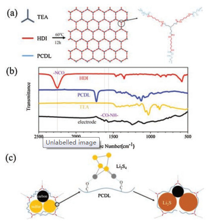
Fig. 1a shows the synthesis process of PTH binder by in-situ polymerization reaction of TEA, HDI and PCDL, in which the carbamate group is formed by the reaction between isocyanate group and hydroxyl group at a relatively low temperature (60 ℃)
(Fig. S1 in Supporting information). Sulfur cathode slurry is usually dried at 60 ℃ and the PTH binder could be in-situ polymerized during this process. The TEA molecule possesses three reactive sites which contribute to the cross-linked structure that joints by covalent bonds in PTH. Among all the functional groups, carbonyl group shows an outstanding chemical adsorbability to polysulfide [34]. PCDL was chosen as the monomer to form PTH because of continuous carbonyl groups on its molecular chain. To clarify the formation of functional groups in PTH during polymerization, Fourier transform infrared (FTIR) measurements were carried out on the three monomers and as-prepared PTH-bare S cathode. As shown in Fig. 1b, we can observe two major changes of characteristic peaks. On one hand, the peaks at 1564.02 cm-1
(anime C—N, stretching) and 1618.27 cm-1 (anime C=O, stretching) appears on the spectrum of PTH-bare S cathode, which means the formation of methyl amide groups. On the other hand, the peak at 2248.75 cm-1 (-NCO, stretching) is not observed, which means the disappearance of isocyanate groups. Those two obvious changes proved that the PTH binder could be formed by polymerization reaction of TEA, HDI and PCDL in PTH-bare S electrode. The stability of PTH film in the liquid electrolyte was tested by soaking the PTH film in the electrolyte. As displayed in Fig. S2, there was no size change in the PTH film after soaking in the liquid electrolyte for 24 h, suggesting excellent stability of PTH in liquid electrolyte.
Figure 1
Figure 1.
(a) Schematic illustration of the synthesis process of PTH binder by in-situ polymerization of monomer TEA, HDI and PCDL and the molecular structure of PTH;
(b) FTIR spectra of monomers and PTH-bare S electrode; (c) Schematic illustration of protection of cathode components by PTH binder.
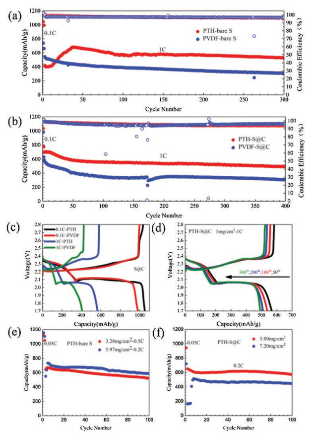
To prove the superiority of PTH binder, the electrochemical performance of Li-S battery with PTH binder and bare sulfur cathode were measured and compared with that of the battery with the PVDF binder and bare sulfur. As shown in Fig. 2a, at a rate of 0.1 C, the PTH-bare S electrode delivers an initial charge capacity of 1043.3mAh/g. When it increases to 1 C, the PTH-bare S electrode delivers an increasing capacity as the contact between sulfur particle and liquid electrolyte getting better. And the PTH-bare S electrode reminds a stable capacity of 518.4mAh/g after 300 cycles. As comparison, the PVDF-bare S electrode shows a much lower initial capacity of 738.9 mAh/g at 0.1 C and poor cycle performance at 1 C with a capacity of only 308.6 mA h/g after 300 cycles. The effect of PTH binder was also evaluated in the sulfur and carbon composite cathode. It can be seen from Fig. 2b, the PTH-S@C cathode could deliver a capacity of 694.5mAh/g at 1 C and remained over 70% after 400 cycles when sulfur mass loading is 1 mg/cm2, which is obvious better than that of the PVDF-S@C cathode. From the charge-discharge profiles of battery with PTHS@C and PVDF-S@C electrodes in Fig. 2c, we can observe that the PTH-S@C cathode presents much lower polarization voltage and longer charge-discharge plateau than that of cathode with PVDF. In addition, the charge-discharge plateau almost does not change during long cycle process as shown in Fig. 2d. The outstanding cycle performance of cathode with PTH may be attributed to its rich functional groups (carbonyl group) and strong cross-linked structure of PTH binder. Those functional groups could adsorb polysulfide chemically [34] and keep polysulfide away from lithium metal anode. On the other hand, the strong cross-linked structure of PTH binder enables the integrity of the electrode structure under the volume expansion of sulfur during cycling. Therefore, the PTH binder could restrain the shuttle effect and prevent electrode pulverization at the same time. The cycle performance of bare S electrode and composite cathode with PTH is improved obviously.
Figure 2
Figure 2.
(a) Cycle performance of cell with PTH-bare S and PVDF-bare S electrodes at 1 C. (b) Cycle performance of cell of PTH-S@C and PVDF-S@C electrodes at 1 C. (c) Galvanostatic charge-discharge profiles of PTH-S@C and PVDF-S@C electrodes at 0.1 C and 1 C. (d) Galvanostatic charge-discharge profiles of PTH-S@C from 50th to 300th cycle. High sulfur loading cycle performance of cell with PTH-bare S cathode (e) and PTH-S@C electrode (f).
High sulfur mass loading performance is very important for the real application of Li-S battery. To verify the effect of PTH binder on electrochemical performance of battery with high sulfur mass loading, cathodes with high sulfur mass loading were made and examined. Fig. 2e presents that the PTH-bare S cathode with 5.97 mg/cm2 sulfur mass loading shows an initial capacity of 1155.9mAh/g at 0.05 C and keeps at 733.3mAh/g at 0.2 C, with a retention of 585.5mAh/g after 100 cycles. The PTH-bare S electrodes with 3.28 mg/cm2 also delivers a high and stable capacity. Moreover, the battery with PTH-S@C cathode shows more stable cycle performance with high sulfur loading (Fig. 2f). When sulfur mass loading raised to 5.00 mg/cm2, the PTH-S@C electrode shows an initial capacity of 943.6mAh/g at 0.05 C and remains at 651.8mAh/g at 0.2 C with a retention of 574.1mAh/g after 100 cycles. When sulfur mass loading further raised to 7.20 mg/cm2, the PTH-S@C electrode shows a capacity of 720.2mAh/g at 0.05 C and 513.8mAh/g at 0.2 C, with a retention of 86.8% after 100 cycles. Therefore, both of the pure S and S@C cathode with high sulfur mass loading using PTH present excellent cycling stability.
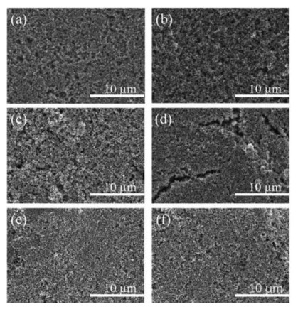
The cathode morphology change after cycling performance was characterized by SEM. It can be seen clearly in Fig. 3a that the PTHbare S electrode surface before cycling tests is smooth and the sulfur and Super P particles are distributed homogeneously. On the contrary, the PVDF-bare S electrode surface is uneven, and there are obvious agglomerate particles on the surface (Fig. 3c). After 200 cycles at 1 C, obvious cracks appear in PVDF-bare S electrode (Fig. 3d), while the PTH-bare S electrode keeps the integrity after cycling(Fig. 3b). This result proves that the strong cross-linked structure of PTH binder ensures the integrity of electrode, and there are no destruction signs observed on PTH-bare S electrode surface. In addition, as it is seen in Figs. 3e and f, there is also no destruction sign appears on PTH-S@C electrode surface. From the cross section images of the cathode before and after cycling in Figs. S3a and b (Supporting information), it can be seen that thickness of as-prepared PTH-bare S electrode is about 16 mm, and it keeps at the same dimension after 200 cycles at 1 C. Combining the surface and cross section images of electrodes, it is obtained that the strong cross-linked structure of the PTH binder can effectively endure the volume change of bare S electrode and protect it from contacting the electrolyte to achieve excellent cycling stability.
Figure 3
Figure 3.
SEM images of charged electrode. (a) As-prepared PTH-bare S electrode; (b) PTH-bare S electrode after 200 cyclesat 1 C; (c) As-prepared PVDF-bare S electrode;
(d) PVDF-bare S electrode after 200 cycles at 1 C; (e) As-prepared PTH-S@C electrode; (f) PTH-S@C electrode after 200 cycles at 1 C.
To clarify the polysulfide adsorption effect of PTH binder, three kinds of composite powder (super P, super P/PVDF and super P/PTH) were added into the polysulfide (Li2S6) solution (3.75 × 10⁻⁶ mol/L) with same amount. We can see from Fig. S4 (Supporting information) that the as-prepared polysulfide solution exhibits light yellowish color initially and then the color changed after standing for 24 h. The polysulfide solution with super P/PTH becomes transparent, which means that the polysulfide has been adsorbed by super P/PTH. Whereas, the rest polysulfide solution keeps yellow, which means super P and PVDF cannot effectively adsorb the polysulfide. Those experimental phenomena prove that the PTH binder has excellent adsorbability to polysulfide.
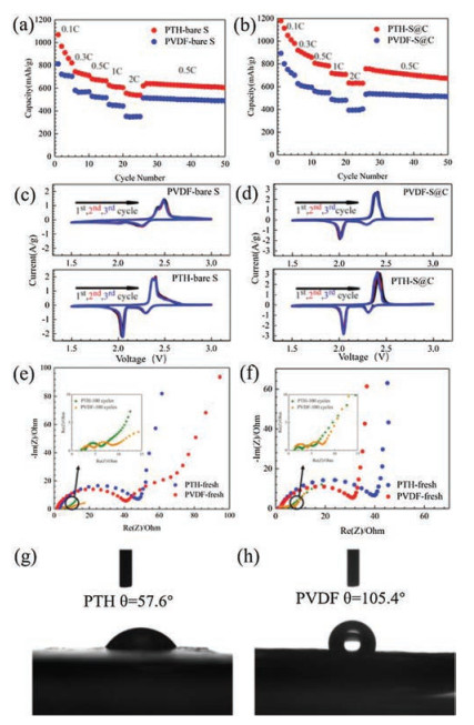
Rate performance of Li-S battery was measured under different rate of 0.1 C, 0.3 C, 0.5 C, 1 C and 2 C. Fig. 4a presents that PTH-bare S electrode delivers the capacities of 1067.5, 744.4, 680.8, 625.3 and 556.7mAh/g at 0.1, 0.3, 0.5, 1 and 2 C, respectively. It is obvious that the PTH-bare S electrode shows obviously higher capacity than that of battery with PVDF-bare S electrode. Similar behavior can be also found for the S@C using PTH binder (Fig. 4b). Better rate performance in the PTH containing cathode indicates faster lithium-ion transportation with the assistance of the polar groups on the PTH molecular chains. Figs. 4g and h show the contact angle of water on PTH and PVDF membranes, respectively. The contact angle of water on PTH membrane is obviously larger than that of water on the PVDF membrane, which indicates that the S electrode using PTH possesses superior wettability with polar liquid electrolyte than that of the S electrode with PVDF. Better wettability with liquid electrolyte means the better lithium-ion transportation capability [35]. Moreover, continuous oxygen atoms on PTH binder molecular chains also could promote the transportation of lithium-ion [36]. When the current density goes back to 0.5 C, the capacity of battery with PTH-bare S electrode goes back to a value of 639.9mAh/g and keeps stable. This means that the strong cross-linked structure of PTH binder can facilitate the electrode to stay stable at high rate charge-discharge process. Superiority of PTH binder for rate performance is also justified by the charge-discharge curve of PTH-bare S and PVDF-bare S electrodes at different current densities (0.3 C, 1 C and 2 C, Fig. S5a in Supporting information). During charge process, a lower plateau voltage is observed, suggesting that less polarization and better lithium-ion transportation network is achieved in PTH-bare S electrode. During discharge process, the second discharge plateau of PTH-bare S electrode is obviously longer than that of cathode with PVDF. This phenomenon can be explained by the more utilization of sulfur and good restriction of polysulfide in PTH-bare S electrode.
Figure 4
Figure 4.
(a) Rate performance of PTH-bare S and PVDF-bare S electrode. (b) Rate performance of PTH-S@C and PVDF-S@C. CV of Li-S batteries with (c) PTH-bare S and PVDF-bare S electrode, and (d) PTH-S@C and PVDF-S@C electrode at a scan rate of 0.1 mV/s. EIS of (e) PTH-bare S and PVDF electrode, and (f) PTH-S@C and PVDFS@C electrode. Contact angle of water on (g) PTH and (h) PVDF membranes.
Cyclic voltammograms (CV) and electrochemical impedance spectroscopy (EIS) tests were carried out to study the PTH binder's effect on the lithium-ion transportation in PTH-bare S electrode.
Fig. 4c shows the CV curve of battery with PTH-bare S electrode and PVDF-bare S electrode for the first 3 cycles. There are two sharp reduction peaks on the CV curve of PTH-bare S electrode. The first one at 2.29 V refers to the translation of S8 to long-chain polysulfide (Li2Sn, 4 ≤ n ≤ 8). The second one at 2.05 V indicates the further translation of mid-chain polysulfide to short-chain polysulfide (Li2Sn, 1 ≤ n < 4). During the oxidation process, the oxidation peak at 2.39 V refers to the translation of Li2S to polysulfide (Li2Sn, 1 < n ≤ 8) and sulfur [37, 38]. In sharp contrast, the CV curve of PVDF-bare S electrode shows a very small second peak and lower reduction peak voltage (2.23 V and 2.00 V) than PTH-bare S electrode during reduction scanning. During oxidation scanning, the oxidation peak voltage of PVDF-bare S electrode (2.49 V) is obviously higher than that of PTH-bare S electrode (2.39 V). Moreover, the peak current density of PTH-bare S electrode is much bigger than that of PVDF-bare S electrode. The less polarization voltage and bigger peak current density proves the better lithium-ion transportation in the PTH-bare S electrode, which agrees with the result of rate test. In the meanwhile, the good repeatability of the CV curve for the first 3 cycles agrees with the stable cycle performance of PTH-bare S electrode. The EIS of Fig. 4e presents that the battery with PTH-bare S electrode (Rct = 46.57 V) has a similar impedance with that of battery with PVDF-bare S electrode (Rct = 39.37 V) at fresh state. After 100 cycles at 1C, the internal impedance of battery with PTH-bare S electrode (Rf = 1.11 V, Rct = 2.68 V) becomes obviously smaller than that of battery with PVDF-bare S electrode (Rf = 2.85 V, Rct = 3.83V). When it comes to the CV and EIS tests of S@C electrode (Figs. 4d and f), the tendency is quite similar with that of bare S electrode. The less impedance of bare S and S@C electrodes using PTH binder results in its better rate performance and better lithium-ion transportation, that contribute to the excellent rate and cycling performance of Li-S battery.
In summary, we put forward a facile method to achieve a novel cross-linked binder for cathode in Li-S battery. By utilization of the high activity between isocyanate group and hydroxyl group, binder with strong 3D network was in-situ polymerized to restrain volume expansion of sulfur. The achieved PTH binder possesses continuous oxygen atoms and good wettability with liquid electrolyte, which could promote the transportation of lithiumion to improve the rate performance. In addition, the rich functional groups (containing oxide and nitrogen atoms) on PTH molecular chains could chemically adsorb polysulfide to suppress polysulfide shuttle effect and improve the cycle performance of LiS battery. The PTH-bare S cathode having a mass loading of 5.97 mg/cm2 delivers a capacity of 733.3mAh/g at 0.2 C, and remains 585.5mAh/g after 100 cycles. This novel in-situ polymerized cross-linked PTH binder shows a superior effect on restrain the volume change of sulfur and suppressing the shuttle effect of polysulfide. This work opens up an avenue to the application of Li-S battery in a large scale.
Acknowledgments
This work was supported by the National Natural Science Foundation of China (No. 51672156), Guangdong special support program (No. 2015TQ01N401), Guangdong Province Technical Plan Project (Nos. 2017B010119001 and 2017B090907005), Shenzhen Technical Plan Project (Nos. JCYJ20170412170706047, JCYJ20170307153806471 and GJHS20170314165324888), and ShenzhenGraphene Manufacturing Innovation Center (No. 201901161513).
Figure 1
(a) Schematic illustration of the synthesis process of PTH binder by in-situ polymerization of monomer TEA, HDI and PCDL and the molecular structure of PTH;
(b) FTIR spectra of monomers and PTH-bare S electrode; (c) Schematic illustration of protection of cathode components by PTH binder.
Figure 2
(a) Cycle performance of cell with PTH-bare S and PVDF-bare S electrodes at 1 C. (b) Cycle performance of cell of PTH-S@C and PVDF-S@C electrodes at 1 C. (c) Galvanostatic charge-discharge profiles of PTH-S@C and PVDF-S@C electrodes at 0.1 C and 1 C. (d) Galvanostatic charge-discharge profiles of PTH-S@C from 50th to 300th cycle. High sulfur loading cycle performance of cell with PTH-bare S cathode (e) and PTH-S@C electrode (f).
Figure 3
SEM images of charged electrode. (a) As-prepared PTH-bare S electrode; (b) PTH-bare S electrode after 200 cyclesat 1 C; (c) As-prepared PVDF-bare S electrode;
(d) PVDF-bare S electrode after 200 cycles at 1 C; (e) As-prepared PTH-S@C electrode; (f) PTH-S@C electrode after 200 cycles at 1 C.
Figure 4
(a) Rate performance of PTH-bare S and PVDF-bare S electrode. (b) Rate performance of PTH-S@C and PVDF-S@C. CV of Li-S batteries with (c) PTH-bare S and PVDF-bare S electrode, and (d) PTH-S@C and PVDF-S@C electrode at a scan rate of 0.1 mV/s. EIS of (e) PTH-bare S and PVDF electrode, and (f) PTH-S@C and PVDFS@C electrode. Contact angle of water on (g) PTH and (h) PVDF membranes.

 DownLoad:

 下载:
下载:


