zmsun@seu.edu.cn (Z. Sun). 1 These authors contributed equally to this work.
Received Date:
03 January 2025 Accepted Date:
16 March 2025 Revised Date:
11 March 2025 Available Online:
15 August 2025
Abstract:
The ineluctable introduction of lithium salt to polymer solid-state electrolytes incurs a compromise between strength, ionic conductivity, and thickness. Here, we propose Al2O3-coated polyimide (AO/PI) porous film as a high-strength substrate to support fast-ion-conducting polymer-in-salt (PIS) solid-state electrolytes, aiming to suppress lithium dendrite growth and improve full-cell performance. The Al2O3 coating layer not only refines the wettability of polyimide porous film to PIS, but also performs as a high modulus protective layer to suppress the growth of lithium dendrites. The resulting PI/AO@PIS exhibits a small thickness of only 35 µm with an outstanding tensile strength of 11.3 MPa and Young's modulus of 537.6 MPa. In addition, the PI/AO@PIS delivers a high ionic conductivity of 0.1 mS/cm at 25 ℃. As a result, the PI/AO@PIS enables symmetric Li cells to achieve exceptional cyclability for over 1000 h at 0.1 mA/cm2 without noticeable lithium dendrite formation. Moreover, the PI/AO@PIS-based LiFePO4Li full cells demonstrate outstanding rate performance (125.7 mAh/g at 5 C) and impressive cycling stability (96.1% capacity retention at 1 C after 200 cycles). This work highlights the efficacy of enhancing the mechanical properties of polymer matrices and extending cell performance through the incorporation of a dense inorganic interface layer.
The liquid organic electrolytes commonly employed in traditional lithium-ion batteries present significant risks of flammability and explosiveness, which inherently limit further advancements in battery safety [1, 2]. Solid-state lithium metal batteries, by circumventing the safety concerns associated with liquid organic electrolytes and utilizing high-voltage cathodes in conjunction with Li metal anode, offer a solution that not only enhances safety but also substantially increases energy density [3-7]. The most essential component of these batteries is the solid-state electrolytes (SSEs), a material critical for ionic conduction, electron insulation, and the separation of electrodes [8, 9]. Among all classes of SSEs, polymer SSEs exhibit favorable properties such as optimal flexibility, superior interface contact, ease of preparation, excellent electrochemical and thermal stability, and cost-effectiveness, which make them viable for large-scale manufacturing [10]. However, their limited ionic conductivity at room temperature (< 10–1 mS/cm) poses a significant barrier to widespread application, and the suboptimal thickness of polymer SSEs impedes the development of energy density [11-13].
Efforts to enhance the ionic conductivity of polymer SSEs have largely focused on polymer modification, lithium salt exploitation, and the incorporation of fillers [14-19]. Nevertheless, the polymer SSEs produced by these methods often suffer from low mechanical strength and considerable thickness, which impede their practical implementation [20-23]. For instance, previous works have utilized Li6.4La3Zr1.4Ta0.6O12 as a filler in a poly(vinylidene fluoride-co-hexafluoropropylene) (PVH) composite SSE, achieving an ionic conductivity of 1.2 mS/cm at room temperature [24]. However, its tensile strength remained at a suboptimal 1.3 MPa. In response to these challenges, researchers propose the use of ultrathin, high-strength porous polymer separators, such as polyethylene/polypropylene separators or polyimide (PI) porous separators, to enhance polymer SSEs while simultaneously reducing their thickness. Zhao et al. demonstrated the preparation of an SSE film with a thickness of just 30 µm by modifying a PP separator with covalent organic polymer network [25]. However, the suboptimal contact between the polymer SSEs and the porous separators resulted in significant interface issues, which in turn adversely affected both strength and durability [26, 27].
Polymer layer modification has been shown to improve interfacial contact. For instance, Zhang et al. developed a poly(lithium acrylate-co‑butyl acrylate) layer that enhanced the wettability of the PP separator [28]. Unfortunately, this improvement came at the expense of porosity and electrolyte uptake. In contrast, inorganic interface layers with high strength and modulus, such as SiO2 and Al2O3, demonstrated superior wettability toward polymer solutions [16, 29-31]. Wang et al. further noted that the PVH solution exhibited better wettability on hierarchically porous SiO2 separators compared to PP-based separators, though the brittleness of SiO2 impeded further progress [32]. Coating with Al2O3 has been found to improve both the thermal stability and mechanical properties of polymer separators [31]. Blake et al. investigated the combination of poly(vinylidene fluoride) (PVDF) and Al2O3 supported by PI porous separators and found that, while the Al2O3/PVDF combination significantly improved wettability and enhanced ionic conductivity, but according to the dispersion of Al2O3 nanoparticle, the Li dendrites can still pierce polymer matrix [33]. In summary, Al2O3 is promising as an interfacial layer between SSEs and Li anode, and we designed a dense inorganic interface layer to improve the wettability of PI and resistance of Li dendrites.
In this work, we explored the effects of the Al2O3 interface layer for PI to support polymer-in-salt (PIS) electrolyte films, aiming to enhance the overall performance of PIS. PIS is a method that represents a straightforward strategy for increasing the ionic conductivity of polymer SSEs by mixing polymer matrix and abundant lithium salt. The PI porous separator, when coated with Al2O3 (labeled as PI/AO), exhibits significantly improved wettability with PIS (labeled as PI/AO@PIS), leading to enhanced tensile strength of 11.3 MPa and Young's modulus of 537.6 MPa, while maintaining superior ionic conductivity of 0.1 mS/cm and reducing the overall thickness to just 35 µm. Despite the reinforcement of thermostability, the PI/AO@PIS-based symmetrical Li metal cells perform amazing cyclability at 0.1 mA/cm2 for over 1000 h without noticeable Li dendrites formation. Moreover, the LiFePO4 (LFP)|PI/AO@PIS|Li full cells have distinguished rate capability (125.7 mAh/g at 5 C) and cyclability (96.1% capacity retention at 1 C after 200 cycles).
To prepare PI/AO@PIS, 0.5 g of PVH (Mw = 455, 000, Macklin) and 0.75 g of lithium bis(trifluoromethanesulfonyl)imide (LiTFSI, 99.9%, Macklin) were dissolved into 6 mL of N-methylpyrrolidone (NMP) (≥99.9% metals basis, Aladdin), stirring at 50 ℃ for 12 h, to form a homogeneous PIS solution. PI/AO separators (20 µm Hinanofiber) were immersed in the obtained PIS solution for 2 min and removed excess PIS solution on the surface by blading. After vacuum-drying at 100 ℃ for 24 h, the PI/AO@PIS had been made. The pure PIS films were prepared by solution cast that added 3 mL PIS solution in the ultra-flat glass petri dish with a diameter of 90 mm, vaporizing a lot of solvent at 80 ℃ and vacuum-drying at 100 ℃ for 24 h. All SSEs were stored in an Ar-filled glovebox before use. SEM images were acquired using a Nova Nano SEM450 (field emission) or a FEI Sirion scanning electron microscope. The stress-strain curves were recorded by an MTS E43 universal tensile testing machine. The TGA curves were acquired using a Netzsch STA449 F3 analyzer under N2 flow with a heating rate of 10 ℃/min. The contact angle was measured by a DataPhysics OCA25LHT-SV contact angle goniometer.
Coin-type 2023 cells were used for both symmetrical- and full-cell assembly. For symmetrical cells, SSEs were sandwiched by Li foils. For full cells, SSEs were sandwiched by LFP cathodes and Li foils. To prepare the cathodes, LFP, conductive additives (Super P), and binders (PVDF) (80:10:10 wt%) were mixed in NMP, forming a homogeneous slurry. The obtained slurry was then coated on an Al foil, followed by vacuum drying at 110 ℃ for 12 h. The coated Al foil was pouched into discs with a diameter of 10 mm. The mass loading of LFP is around 2.8 mg/cm2, unless otherwise specified. Note that, in all full cells, 5 µL of liquid electrolyte (1 mol/L LiPF6 in EC: DEC = 1:1 vol%) was added on the surface of cathodes to improve its contact with SSE and to facilitate the Li+ diffusion in cathodes. The control samples (i.e., pure PIS and PI/AO-based full cells) were also added with liquid electrolyte on cathode surfaces to enhance ion transport at the interface. All the electrochemical tests were performed on a Chenhua CHI660 or CHI604 electrochemical workstation. GCD tests were conducted on a Lanhe LAND-CT2001A battery tester. Ionic conductivities were calculated based on EIS profiles, which were recorded on a 2023-type cell configuration of stainless steel|SSE|stainless steel. The EIS measurements were carried out in the frequency range of 106–10–1 Hz at different temperatures (25–70 ℃). Electrochemical window voltages were obtained by an LSV method (sweeping range: 1.0–6.0 V; sweeping rate: 1 mV/s). The C-rate of LFP-based full cells corresponded to the current density of 170. The working voltage range of LFP-based full cells was 2.8–4.2 V (vs. Li+/Li).
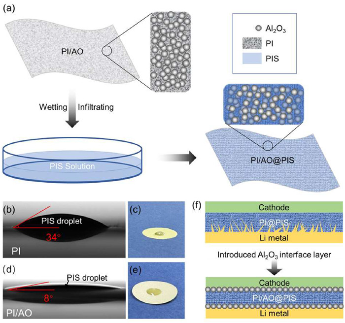
Fig. 1a illustrates the standard synthesis method for preparing PI/AO@PIS. The initial step involves dissolving PVH and LiTFSI at a mass ratio of precisely 1.0:1.5 in NMP, yielding a well-dispersed PIS solution. Following this, the PI separators coated with Al2O3 undergo a carefully controlled wetting and infiltration process, ensuring the complete absorption of the PIS solution. As a result, the PI/AO becomes saturated with PIS, facilitating a straightforward introduction of an Al2O3 interface layer within the SSE films. Subsequent tests to determine the wettability and contact angle of PI/AO reveal a contact angle between the PIS droplet and the PI separator at 34°, indicating limited PIS infiltration (Figs. 1b and c). By contrast, the contact angle between PI/AO and the PIS droplets measures only 8°, suggesting a significantly evident probability of introducing inorganic interface layers through this technique (Figs. 1d and e). Fig. 1f further elucidates the mechanism by which the inorganic interface layer serves to inhibit lithium dendrite growth. In comparison with a pure PI film, the rigid and dense Al2O3 interface layer acts as a robust barrier, which effectively prevents punctures from lithium dendrites. This barrier quality promotes uniform deposition and stripping of lithium metal anode at the charge/discharge cycles, ultimately supporting the structural and functional stability of the cell system.
Figure 1
Figure 1.
Preparation process and Al2O3 coating function of solid electrolyte PI/AO@PIS. (a) The compendiary preparation process of PI/AO@PIS film. (b, c) The contact angle between pure PI separator and PIS solution, and wettability between pure PI separator and PIS solution. (d, e) Contact angle between PI/AO and PIS solution, and wettability between PI/AO and PIS solution. (f) Lithium branch generation and growth inhibited by Al2O3 coating.
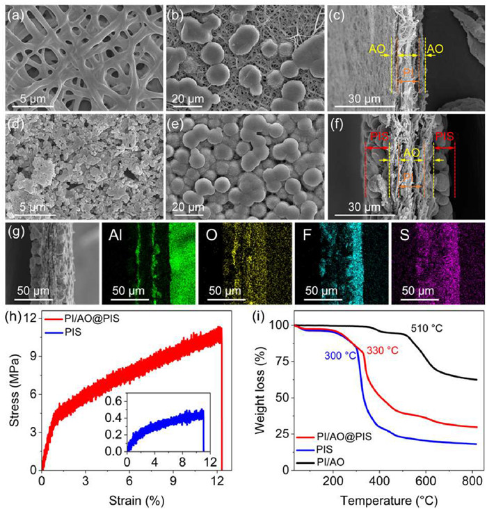
Materials morphology was analyzed through scanning electron microscopy (SEM). The PI porous separator exhibits a well-defined three-dimensional network structure with pore diameters around 12 µm (Fig. 2a). In PI/AO, the surface of the PI separator becomes uniformly encrusted with Al2O3 particles while maintaining sufficient porosity to allow PIS solution infiltration (Fig. 2b). The cross-sectional SEM image of PI/AO shows that the Al2O3 coating layer has a thickness of approximately 2 µm and that the PI/AO film reaches a total thickness of 20 µm (Fig. 2c). When infiltrated with PIS, the PI separator surface was sparsely distributed with PIS particles, indicating its poor wettability and compatibility (Fig. 2d). In contrast, the PI/AO surface was coated with homogeneous and dense PIS particles, with spherical morphology similar to pure PIS (Fig. 2e). Furthermore, cross-sectional analysis confirms that PIS adheres uniformly and firmly on both sides of the Al2O3 coating, yielding an ultrathin PI/AO@PIS film of approximately 35 µm (Fig. 2f), significantly thinner than the pure PIS layer (240 µm) (Fig. S1b in Supporting information).
Figure 2
Figure 2.
Characterizations of morphology, tensile strength, and thermal stability. (a) Top-surface SEM image of pure PI separator. (b, c) SEM images of top-surface and cross-section of PI/AO. (d) SEM image of the top-surface of PI@PIS. (e, f) SEM images of top-surface and cross-sectional of PI/AO@PIS. (g) EDS image of the cross-section of PI/AO@PIS. (h) Stress-strain curves of PI/AO@PIS and PIS films. (i) TGA curves of PI/AO@PIS, PIS, and PVH.
Energy dispersive spectroscopy (EDS) was employed to observe the cross-sectional elemental distribution of PI/AO@PIS. Signals of Al confirm the persistent, uniform, and dense distribution of Al2O3 particles on both sides of PI. F and S signals, indicative of PVH and LiTFSI, respectively, suggest that PIS penetrates uniformly into the porous PI/AO (Fig. 2g) establishing Li+ channels in PI/AO and that the PI/AO@PIS is successfully prepared. Mechanical properties were assessed through tensile testing, revealing that the ultrathin PI/AO@PIS exhibits superior tensile strength and elastic modulus compared to thicker PIS samples (Fig. 2h), underscoring its potential to inhibit lithium dendrite growth.
Thermal stability analysis via thermogravimetric analysis (TGA) reveals that PI/AO@PIS exhibits a higher decomposition temperature relative to PIS (Fig. 2i). For the conventional solution casting method, ineluctable residual solvent extremely undercut Coulombic efficiencies of polymer SSEs and its long-term cycling stability by irreversible side reactions which cause some interfacial issues [34-36]. Up to 200 ℃, mass loss is predominantly attributed to the evaporation of residual NMP solvent, which constitutes 3.8 wt% of PI/AO@PIS, contrasted with 4.7 wt% of NMP in PIS. The introduction of the Al2O3 interface substantially enhances the thermal stability of PIS, emphasizing its potential to work at high current density and temperature.
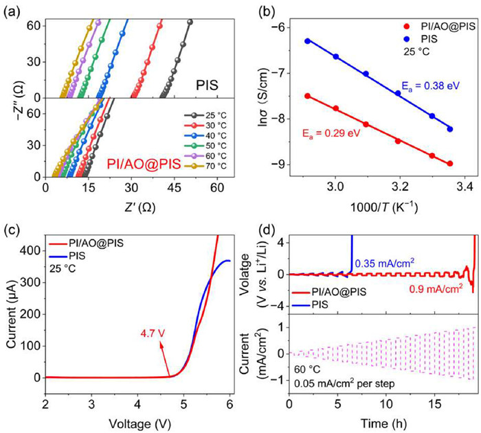
Electrochemical impedance spectroscopy (EIS) is performed to measure the ionic conductivity of PI/AO@PIS compared to PIS. Symmetrical cells with stainless steel electrodes were tested across a temperature range from 25 ℃ to 70 ℃. At 25 ℃, the PI/AO@PIS and PIS exhibits resistances of 13.6 Ω and 40.8 Ω, respectively, corresponding to ionic conductivities of 0.1 mS/cm and 0.3 mS/cm (Fig. 3a). Calculated via the Vogel-Tammann-Fulcher (VTF) model [37], the activation energy of PI/AO@PIS is 0.29 eV (Fig. 3b), significantly lower than that of PIS (0.38 eV), suggesting a reduced energy barrier for Li+ migration in PI/AO@PIS. It also shows that the ionic conductivity of PI/AO@PIS is less dependent on the temperature.
Figure 3
Figure 3.
Li+ ionic conductivity and electrochemical stability. (a) EIS profiles of PIS and PI/AO@PIS at different temperatures. (b) Arrhenius plots of PIS and PI/AO@PIS. (c) LSV curves of PIS and PI/AO@PIS at 25 ℃ with scanning rate = 1 mV/s. (d) Polarization voltage curves of PIS and PI/AO@PIS-based Li metal symmetrical cells at ladder-increased current densities at 60 ℃.
To further test the electrochemical stability of PI/AO@PIS, stainless steel|SSEs|Li cells were assembled and tested for their electrochemical window by linear sweep voltammetry (LSV), as shown in Fig. 3c. In the voltage range less than 4.7 V, the current does not change significantly, and the electrochemical stability window of PI/AO@PIS can be obtained up to 4.7 V. There is no change in the electrochemical stability window because of the heterogeneous dispersion of Al2O3.
A ladder-increased current density method was employed to assess the critical current density (CCD) of the Li|PI/AO@PIS|Li and Li|PIS|Li symmetric cells at 60 ℃ (Fig. 3d). As the current density gradually increased, the overpotential for both PI/AO@PIS and PIS exhibit a rising trend. Notably, the overpotential for PI/AO@PIS remains consistently lower than that of PIS, primarily due to its reduced ohmic impedance and superior interface contact. When the current density reaches 0.35 mA/cm2, the overpotential of PIS surges sharply, resulting in cell failure as it exceeds the protection voltage. In contrast, the PI/AO@PIS cell maintains a stable overpotential, which only increases to 265.8 mV even at a current density of 0.9 mA/cm2. This indicates the remarkable stability of the PI/AO@PIS under higher current densities compared to PIS.
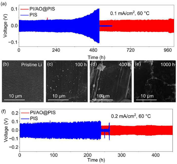
We assessed the stability of PI/AO@PIS when paired with lithium metal anodes by conducting tests on Li symmetric cells at a current density of 0.1 mA/cm2 at 60 ℃ (Fig. 4a). After 300 h of cycling, the overpotential of PIS begin to increase gradually. When this overpotential reaches 99.8 mV, it then experiences a sudden drop to approximately 1.2 mV, indicating that the low modulus and low strength of PIS are insufficient to withstand the growth of lithium dendrites, ultimately resulting in a short circuit and subsequent failure of the cell. In stark contrast, the Li symmetric cells utilizing PI/AO@PIS exhibit remarkable stability, enduring over 1000 h of cycling with an overpotential that remains stable at around 34.3 mV, significantly lower than that of the PIS-based symmetric cells. Thus, PI/AO@PIS effectively mitigates the short circuit issues associated with lithium dendrites puncture.
Figure 4
Figure 4.
Li plating/stripping and post-failure characterization of Li metal symmetrical cells. (a) Voltage profiles of Li|PIS|Li and Li|PI/AO@PIS|Li cycled at 0.1 mA/cm2 at 60 ℃. (b) SEM image of the top-surface of unused Li metal. (c–e) SEM images of the top-surface of Li metals after cycling at 0.1 mA/cm2 at 60 ℃ for 100, 400, and 1000 h, respectively. (f) Voltage profiles of Li|PIS|Li and Li|PI/AO@PIS|Li cycled at 0.2 mA/cm2 at 60 ℃.
To characterize the morphology of the lithium metal anode surface in PI/AO@PIS-based symmetric cells over different cycling durations at 60 ℃ and 0.1 mA/cm2, scanning electron microscopy (SEM) was employed [38]. Fig. 4b illustrates the surface morphology of the pristine lithium metal, which is notably flat and smooth. After 100 and 400 h of cycling, the lithium metal surfaces remain equally flat and smooth (Figs. 4c and d). Remarkably, even after 1000 h of cycling, the lithium metal surface retains a relatively flat appearance, with no evident formation of lithium dendrites (Fig. 4e).
To further substantiate the assertion that the incorporation of the Al2O3 interface effectively inhibits the growth of lithium dendrites, Li|PI/AO@PIS|Li and Li|PIS|Li symmetric cells were subjected to testing at a current density of 0.2 mA/cm2 at 60 ℃, as depicted in Fig. 4f. With the escalation of current density, the overpotential of the PIS-based symmetric cells experience a significant increase, approaching 100 mV. After 240 h of cycling, the overpotential sharply declines to 16.9 mV, culminating in a short circuit and failure of the cells. Conversely, the PI/AO@PIS-based symmetric cells maintain stability for 450 h, with the overpotential throughout the cycling process remaining consistently stable at 50.3 mV. This indicates that PI/AO@PIS facilitates uniform deposition and stripping of lithium metal, while concurrently inhibiting the formation and puncture of lithium dendrites.
Full cells of LFP|PI/AO@PIS|Li and LFP|PIS|Li were assembled for constant current charge/discharge tests within an electrochemical testing system. The loading of the active material, LFP, on the cathode was approximately 3 mg/cm2, with a charge/discharge voltage range set between 2.8 V and 4.2 V, at a temperature of 60 ℃. To enhance ion transport among the cathode material particles and reduce interfacial impedance with the solid electrolyte, 5 µL of liquid electrolyte (1 mol/L LiPF6 in EC: DEC at a 1:1 vol ratio) was simultaneously added to the cathode side.
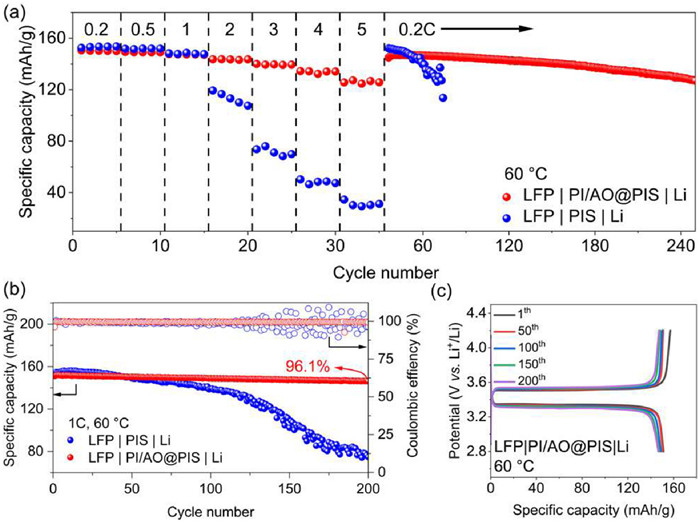
Fig. 5a presents a comparison of the rate and cycling performance between the LFP|PI/AO@PIS|Li and LFP|PIS|Li full cells. When tested at a rate of 0.25 C, the specific capacities of LFP|PI/AO@PIS|Li at current densities of 0.2, 0.5, 1, 2, 3, and 4 C are measured to be 150.6, 149.0, 147.1, 143.6, 139.5, and 134.2 mAh/g, respectively. Notably, the specific capacity of LFP|PI/AO@PIS|Li exhibits only a slight decrease as the current density increases. At a current density of 5 C, the specific capacity remains remarkably high at 125.7 mAh/g. Moreover, upon restoring the current density to 0.2 C, the specific capacity promptly recovers to 144.9 mAh/g. After 200 cycles, the specific capacity stands at 129.9 mAh/g, reflecting a capacity retention of 89.6% relative to the initial value of 144.9 mAh/g.
Figure 5
Figure 5.
LFP-based full-cell performance at 60 ℃. (a) Rate capability and cyclability of PI/AO@PIS and PIS-based full cells. (b) Cycling-specific capacity and Coulombic efficiency of PI/AO@PIS and PIS-based full cells at the current density of 1 C. (c) Galvanostatic charging/discharging (GCD) profiles of LFP|PI/AO@PIS|Li full cells at different cycles.
In stark contrast, the LFP|PIS|Li cells exhibit a significantly lower capacity of only 31.2 mAh/g at a high rate of 5 C. Furthermore, upon reverting to 0.2 C, these cells failed within fewer than 40 cycles, highlighting their inferior rate performance and cycling reversibility. Additionally, the LFP|PI/AO@PIS|Li configuration demonstrates a lower overpotential than the PIS counterpart (Figs. S2a and b in Supporting information).
To further explore the electrochemical stability of PI/AO@PIS over extended cycling, LFP|PIS|Li and LFP|PI/AO@PIS|Li full cells were cycled at a current density of 1 C at 60 ℃. As illustrated in Fig. 5b, the LFP|PI/AO@PIS|Li full cells exhibit an initial specific capacity of 151.1 mAh/g, with a stable cycling capacity of 96.1% retention after 200 cycles and a Coulombic efficiency approaching 100%. In contrast, the LFP|PIS|Li full cells began to experience a sharp decline in capacity after 100 cycles, accompanied by noticeable fluctuations in efficiency. This observation aligns with the results from the symmetric cell tests, demonstrating that PI/AO@PIS possesses superior chemical stability with lithium metal during cycling, thereby maintaining structural integrity.
Furthermore, the charge-discharge voltage curves for different cycles of the LFP|PI/AO@PIS|Li cells are presented in Fig. 5c. After 200 cycles, the overpotential increases from 174 mV to 245 mV, representing an incremental rise of only 71 mV throughout the cycling process, or approximately 0.4 mV per cycle. Overall, the consistent overpotential observed during cycling serves as compelling evidence of the exceptional electrochemical stability of PI/AO@PIS in comparison to PIS (Fig. S3 in Supporting information).
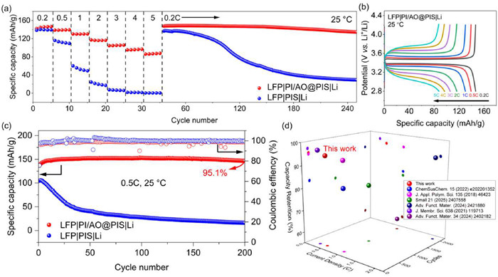
The performance of LFP|PI/AO@PIS|Li cells was also evaluated at 25 ℃. Fig. 6a presents a comparison of the current density performance between LFP|PI/AO@PIS|Li and LFP|PIS|Li. At a current density of 5 C, the specific capacity of LFP|PI/AO@PIS|Li decreases to 87.8 mAh/g, yielding a capacity retention of 59.8%. Although this represents a decline compared to the performance at 60 ℃, it still reflects commendable efficiency. Notably, upon returning the current density to 0.2 C, the specific capacity promptly rebounds to 147.7 mAh/g, surpassing both the initial capacity of 146.8 mAh/g and the 200-cycle capacity of 134.6 mAh/g, resulting in a capacity retention of 91.1% (relative to 147.7 mAh/g).
Figure 6
Figure 6.
LFP-based full-cell performance at 25 ℃. (a) Rate capability and cyclability of PI/AO@PIS and PIS-based full cells. (b) Galvanostatic charging/discharging (GCD) profiles of LFP|PI/AO@PIS|Li full cells at increasing current densities. (c) Cycling specific capacity and Coulombic efficiency of PI/AO@PIS and PIS-based full cells at the current density of 0.5 C. (d) Comparison of capacity retention of PI/AO@PIS with other reported polymer SSEs.
In contrast, the LFP|PIS|Li full cells demonstrate significantly poorer performance; when the current density is increased to 0.5 C, the capacity diminishes to 109.6 mAh/g, and upon further increasing the current density to 5 C, the capacity plummets to a mere 0.5 mAh/g, effectively nearing zero. Upon reverting to a current density of 0.2 C, the cell's capacity has declined to 29.3 mAh/g, with an abysmally low-capacity retention of just 21.4%.
Moreover, the charge-discharge curves of LFP|PI/AO@PIS|Li at increasing current densities are depicted in Fig. 6b. The LFP|PI/AO@PIS|Li cells exhibit relatively lower overpotential at current densities of 0.2, 1, 2, and 5 C; in contrast, the overpotential for LFP|PIS|Li became uncontrollable at 2 C (Fig. S4 in Supporting information).
To further assess the performance of PI/AO@PIS over extended cycles at 25 ℃, the assembled PI/AO@PIS and PIS-based full cells were tested at 0.5 C. As shown in Fig. 6c, the initial specific capacity of the LFP|PI/AO@PIS|Li cells is recorded at 137.7 mAh/g. As the cells are activated, the capacity gradually increases to a stable 152.4 mAh/g after 200 cycles, resulting in a capacity retention of 95.1% while maintaining an efficiency above 99.9%. Conversely, the LFP|PIS|Li cells exhibit an initial specific capacity of only 104.9 mAh/g, which plummets to 16.3 mAh/g after 200 cycles. These results collectively indicate that LFP|PI/AO@PIS|Li exhibits improved rate capability and long-term cycling stability at 25 ℃. Compared with other works, this work performed outstanding capacity retention (Fig. 6d).
In conclusion, we have successfully demonstrated the feasibility of integrating an inorganic interface surface layer into the polymer matrix by coating Al2O3 particles onto the surface of PI. This approach not only confirms that PI/AO@PIS possesses remarkable mechanical properties, electrochemical stability, cycling capability, and a lightweight profile but also establishes that the dense and rigid inorganic interface layer significantly inhibits the growth of lithium dendrites. The PI/AO@PIS exhibits a thickness of 35 µm, accompanied by a tensile strength of 11.3 MPa and an elastic modulus of 537.6 MPa. Furthermore, PI/AO@PIS demonstrates an ionic conductivity of 0.1 mS/cm, an electrochemical window of 4.7 V, and a critical current density of 0.9 mA/cm2 at room temperature. Li|PI/AO@PIS|Li was cycled for 1000 h at 60 ℃ and a current density of 0.1 mA/cm2, during which the overpotential remained stable at approximately 34.3 mV, with no significant growth of lithium dendrites observed. At 25 ℃, the LFP|PI/AO@PIS|Li full cells presented a high specific capacity of 96.9 mAh/g at a current density of 5 C. Simultaneously, at a current density of 0.5 C, the capacity retention was an impressive 95.1% after 200 stable cycles, with a negligible capacity degradation of only 0.02% per cycle. Hopefully, our work could shed light on the mass production of thin yet strong SSE films and finally lead to commercialized solid-state batteries.
Declaration of competing interest
The authors declare that they have no known competing financial interests or personal relationships that could have appeared to influence the work reported in this paper.
B. Halder, M.G. Mohamed, S.W. Kuo, P. Elumalai, Mater. Today Chem. 36 (2024) 101926.
[18]
M. Martinez-Ibañez, E. Sanchez-Diez, L. Qiao, et al., Adv. Funct. Mater. 30 (2020) 2000455.
[19]
S. Zhao, J. Lu, B. Sheng, et al., Chin. Chem. Lett. 36 (2025) 110008.
[20]
Y. Ma, C. Wang, K. Yang, et al., ACS Appl. Mater. Interface. 15 (2023) 17978–17985. doi: 10.1021/acsami.3c02084
[21]
H. Liang, L. Wang, A. Wang, et al., Nano-Micro Lett. 15 (2023) 42.
[22]
A. Du, H. Lu, S. Liu, et al., Adv. Energy Mater. 14 (2024) 2400808.
[23]
Z. Wang, L. Shen, S. Deng, P. Cui, X. Yao, Adv. Mater. 33 (2021) e2100353.
[24]
Y. Wang, P. Yuan, X.X. Liu, et al., Adv. Funct. Mater. 34 (2024) 2405060.
[25]
Z. Zhao, Y. Pan, H. Chen, et al., Adv. Funct. Mater. 34 (2024) 2402182.
[26]
X. Shi, Z. Jia, D. Wang, et al., Adv. Mater. 36 (2024) e2405097.
[27]
Y. Han, B. Liu, Z. Xiao, et al., InfoMat 3 (2021) 155–174. doi: 10.1002/inf2.12166
[28]
Y. Zhang, Y.Z. Song, J.J. Yuan, et al., J. Appl. Polym. Sci. 135 (2018) 46423.
[29]
M.M. Methani, M. Revilla-Leon, A. Zandinejad, J. Esthet. Restor. Dent. 32 (2020) 182–192. doi: 10.1111/jerd.12535
[30]
M. Choudhuri, D. Choudhury, J. Mukhopadhyay, M. Mukhopadhyay, Macromol. Symp. 388 (2019) 1900031.
[31]
S. Ahmad, S.A. Agnihotry, Curr. Appl. Phys. 9 (2009) 108–114.
[32]
J. Wang, Y. Liu, Q. Cai, et al., Adv. Mater. 34 (2021) 2107957.
[33]
A.J. Blake, R.R. Kohlmeyer, J.O. Hardin, et al., Adv. Energy Mater. 7 (2017) 1602920.
[34]
W. Yang, Y. Liu, X. Sun, et al., Angew. Chem. Int. Ed. 63 (2024) e202401428.
[35]
Y. Yao, Z. Wei, H. Wang, et al., Adv. Energy Mater. 10 (2020) 1903698.
[36]
X. Huang, S. Huang, T. Wang, et al., Adv. Funct. Mater. 33 (2023) 2300683.
[37]
W. Liu, S.W. Lee, D. Lin, et al., Nat. Energy 2 (2017) 17035.
[38]
P. Liu, S. Shen, Z. Qiu, et al., Adv. Mater. 36 (2024) 2312812.
Figure 1
Preparation process and Al2O3 coating function of solid electrolyte PI/AO@PIS. (a) The compendiary preparation process of PI/AO@PIS film. (b, c) The contact angle between pure PI separator and PIS solution, and wettability between pure PI separator and PIS solution. (d, e) Contact angle between PI/AO and PIS solution, and wettability between PI/AO and PIS solution. (f) Lithium branch generation and growth inhibited by Al2O3 coating.
Figure 2
Characterizations of morphology, tensile strength, and thermal stability. (a) Top-surface SEM image of pure PI separator. (b, c) SEM images of top-surface and cross-section of PI/AO. (d) SEM image of the top-surface of PI@PIS. (e, f) SEM images of top-surface and cross-sectional of PI/AO@PIS. (g) EDS image of the cross-section of PI/AO@PIS. (h) Stress-strain curves of PI/AO@PIS and PIS films. (i) TGA curves of PI/AO@PIS, PIS, and PVH.
Figure 3
Li+ ionic conductivity and electrochemical stability. (a) EIS profiles of PIS and PI/AO@PIS at different temperatures. (b) Arrhenius plots of PIS and PI/AO@PIS. (c) LSV curves of PIS and PI/AO@PIS at 25 ℃ with scanning rate = 1 mV/s. (d) Polarization voltage curves of PIS and PI/AO@PIS-based Li metal symmetrical cells at ladder-increased current densities at 60 ℃.
Figure 4
Li plating/stripping and post-failure characterization of Li metal symmetrical cells. (a) Voltage profiles of Li|PIS|Li and Li|PI/AO@PIS|Li cycled at 0.1 mA/cm2 at 60 ℃. (b) SEM image of the top-surface of unused Li metal. (c–e) SEM images of the top-surface of Li metals after cycling at 0.1 mA/cm2 at 60 ℃ for 100, 400, and 1000 h, respectively. (f) Voltage profiles of Li|PIS|Li and Li|PI/AO@PIS|Li cycled at 0.2 mA/cm2 at 60 ℃.
Figure 5
LFP-based full-cell performance at 60 ℃. (a) Rate capability and cyclability of PI/AO@PIS and PIS-based full cells. (b) Cycling-specific capacity and Coulombic efficiency of PI/AO@PIS and PIS-based full cells at the current density of 1 C. (c) Galvanostatic charging/discharging (GCD) profiles of LFP|PI/AO@PIS|Li full cells at different cycles.
Figure 6
LFP-based full-cell performance at 25 ℃. (a) Rate capability and cyclability of PI/AO@PIS and PIS-based full cells. (b) Galvanostatic charging/discharging (GCD) profiles of LFP|PI/AO@PIS|Li full cells at increasing current densities. (c) Cycling specific capacity and Coulombic efficiency of PI/AO@PIS and PIS-based full cells at the current density of 0.5 C. (d) Comparison of capacity retention of PI/AO@PIS with other reported polymer SSEs.

 DownLoad:

 下载:
下载:


