Received Date:
18 October 2024 Accepted Date:
11 December 2024 Revised Date:
06 December 2024 Available Online:
15 November 2025
Abstract:
The escalating demand for advanced energy storage solutions has positioned lithium metal anodes at the forefront of battery technology research. However, the practical implementation of lithium metal anodes is impeded by challenges such as dendrite formation and the inherent instability of the native oxide layer. This study introduces a novel liquid-source plasma technique to create a high-quality solid electrolyte interphase (SEI) composed of LiBr and LiBO2. According to first-principal calculation, LiBO2 optimizes the electrochemical dynamics and LiBr improves Li diffusion at the interfaces, thus protecting the Li metal from severe Li dendrite growth. This well-designed artificial SEI endows the Li metal with remarkable cycling stability over 550 cycles at a current density of 1 mA/cm2, significantly superior to the bare Li anode. Meanwhile, the full cell paired with a high-voltage LiNi0.8Co0.1Mn0.1O2 cathode delivers long-term stability with capacity retention (78% after 200 cycles) at 1 C and excellent rate performance. The findings highlight the importance of interface engineering in optimizing battery performance and longevity.
As energy density of lithium-ion battery nears the theoretical maximum, there is an urgent need for next-generation energy storage systems that can offer significantly higher energy density to satisfy the ever-increasing requirements of electric vehicles and large-scale energy grid storage [1-4]. Lithium metal possesses a theoretical specific capacity of 3860 mAh/g and lowest potential (−3.04 V versus the standard hydrogen electrode) [5]. Consequently, lithium metal, is considered as the "holy grail, " the ideal anode material for the advancement of next-generation battery technologies, including lithium-sulfur (2600 Wh/kg), and lithium-air (3500 Wh/kg) batteries [6-8]. Despite these advantages, the commercial applications of lithium metal anodes in batteries are primarily impeded by the following challenges: (1) The formation of dendritic lithium due to non-uniform distribution of Li+ flux [9]. (2) Significant volume fluctuations during lithium stripping and plating processes [10]. (3) The continuous degradation and regeneration of the solid electrolyte interphase (SEI) due to its inadequate mechanical properties and inconsistent thickness [11, 12]. To solve these issues, the modification of the interfaces of on Li metal are of significant importances.
As reported, the ideal SEI requires the following characteristics: (1) Homogeneous composition and morphology to avoid local aggregation of Li+ leading to nucleation and growth of lithium dendrites [11, 13]. (2) High Li-ion conductivity and fast Li-ion diffusion [14]. These merits can facilitate the fast transfer of active Li ions through the SEI, effectively inhibiting the formation of Li dendrites without structural degradation [15, 16]. (3) Good mechanical properties to accommodate the interfacial deformation during cycling [17-19]. According to the aforementioned requirements, a series of effective artificial SEIs have been implemented to optimize the lithium anodes including inorganic SEI [20, 21], organic SEI [22], allying SEI [23], and composited SEI [24-27]. Among previous SEI layer, inorganic lithium compounds (LiF [28, 29], Li3N [30], LiBr [31, 32], etc.) with the merits of optimal interfacial energy and superior ionic conductivity arouse tremendous attentions, which can facilitate the lateral diffusion of Li+ along the SEI/Li interface and effectively induce a uniform ionic flux, thus suppressing dendrite formation and improving the stability of LMAs [7, 8, 27, 33]. For instance, Liu and colleagues used chemical passivation by bromooctane to generate LiBr-enrich SEI on Li metal. Further, they demonstrated that the crystalline surface (111) of LiBr provides high adsorption energy and low diffusion barrier for Li+ ions, revealing the key role of inorganic LiBr-SEI in inhibiting the growth of dendritic Li [31]. However, the intrinsic brittleness of many of the inorganic components during electrochemical cycling can lead to stress accumulation and thus induce fracture [12, 34]. In addition, some of the SEI inorganic components can hinder ion transport, and their presence in excess can increase interfacial resistance [6, 13]. The lithium-boron composite anode with low density (1.38 g/cm3), high tensile strength (> 6 MPa), and high lithophilicity can theoretically make up for these weaknesses of inorganic SEI [23, 35]. Thus, to combine the advantages of Br and B contained lithium compounds, a new BBr3 low-temperature plasma technology is first proposed to optimize the lithium anodes with well-designed SEI composed of controllable morphology, composition and thickness.
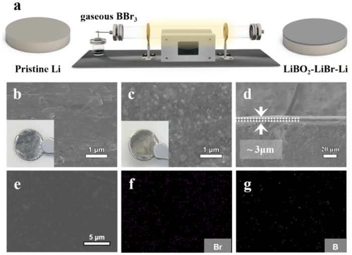
Fig. 1a schematically depicts the preparation process of LiBO2-LiBr-Li. The pristine Li was first placed in a plasma-enhanced chemical vapor deposition (PECVD) apparatus (Fig. S1 in Supporting information). After the excitations of BBr3 plasma (Fig. S2 in Supporting information), the Br* and B* radicals [36] can react with Li2O and Li at room temperature to in-situ produce LiBO2-LiBr SEI. From the scanning electron microscope (SEM) images, it can be observed that the bare Li is uneven with a sliver color (Fig. 1b and Fig. S3a in Supporting information). After BBr3 plasma treatment, the surface of LiBO2-LiBr-Li turns into a color with yellowish metallic luster decorated with numerous nanoparticles. Moreover, the surface became more dense and flat surface at large scale, indicating the formation of SEI layer (Fig. 1c and Fig. S3b in Supporting information). The continuous nanoparticles can effectively reduce the local current density and mitigate the growth of lithium dendrites, while the dense structure can reduce the penetration of the electrolyte and avoid the reaction between electrolyte and lithium metal. From cross-sectional perspective, it can be observed that the thickness of the whole anode was ~200 µm and the in situ formed SEI via plasma shows a thickness of ~3 µm and (Fig. 1d and Fig. S4 in Supporting information). In addition, the elemental mapping images of the illustrate the homogeneous distribution of Br, B and O elements at the LiBO2-LiBr interlayer on the LiBO2-LiBr-Li surface (Figs. 1e-g and Fig. S5 in Supporting information). As for the pristine Li, there is no signal of B or Br (Fig. S6 in Supporting information), which also demonstrate the successful transformation of native Li2O into optimized LiBO2-LiBr SEI.
Figure 1
Figure 1.
(a) Diagram of the synthesis process of LiBO2-LiBr-Li. (b) SEM images of Pristine Li (embedded picture: optical photo). (c) SEM images and (d) Cross-sectional SEM image of LiBO2-LiBr-Li. (e-g) Scanning electron microscopy image of LiBO2-LiBr-Li and the corresponding elemental maps of Br, and B.
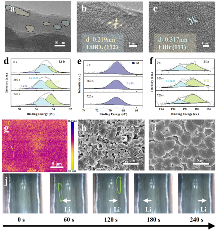
In order to confirm the composition of SEI, we pictured the high-resolution transmission electron microscopy (HRTEM) images of LiBO2-LiBr-Li (Fig. 2a). As observed, the lattice spacings of the artificial SEI layer are determined to be 2.19 and 3.17 Å, matched well with (112) and (111) crystal planes of LiBO2 and LiBr, respectively (Figs. 2b and c). The detail composition and valence state of as-constructed SEI were further analyzed by X-ray photoelectron spectroscopy (XPS) analysis (Figs. 2d-f). In the Li 1s spectrum, there exist characteristic peaks located at 56.8 and 55.3 eV, confirming the in-situ deposition of Li-Br and Li-B-O [21, 28, 37], which are also supported by Br 3d and B 1s spectra. And based on the XPS results of Li 1s, the relative ratio of LiBO2 and LiBr in the LiBO2-LiBr-Li SEI is 88:12. By contrast, the spectrum of pristine Li shows peak belonging to Li2O without distinct peaks belonging to bromine or boron (Fig. S7 in Supporting information). Meanwhile, the compositions of LiBr and LiBO2 also remain almost constant in the longitudinal depth, indicating the homogeneity of the heterogeneous inorganic SEI in terms of composition, which is homogeneous in the plasma treatment process. The above results cooperatively confirm the successful transformation from native Li2O layer into dense and homogeneous LiBO2-LiBrcomposed SEI by plasma technology. Thus, we can utilize the advantages a high interfacial energy of an inorganic layer to boost the Li lateral diffusion along the SEI/Li interface and suppress metallic Li from penetrating into SEI to protect the lithium metal anode. Then, Atomic Force Microscope (AFM) was utilized to assess the morphology of the synthetic SEI and determine the average Young's modulus of LiBO2-LiBr-Li (Fig. 2g). It indicates that the surface of LiBO2-LiBr-Li anode are flat and homogeneous with an overall Young's modulus value of ~8.8 GPa, which effectively mitigates the issues associated with SEI interface disintegration resulting from dendritic expansion and volumetric variations during the cycling process [38, 39]. For validating the advantages of the LiBO2-LiBr SEI, SEM images of the anodes after cycling were conducted. Compared to the pristine Li anodes with large amounts of dendritic lithium and great volume expansion (Fig. 2h), the LiBO2-LiBr-Li anode with LiBr-LiBO2-enriched interphases still maintains a dense and plane morphology without apparent defects (Fig. 2i), indicating its enhanced cycling stability. To better observe the growth of lithium dendrites, in situ optical microscopy was conducted to monitor the morphology transition of optimized and bare Li anodes during the galvanostatic charging and discharging process (10 mA/cm2). Notably, the pristine Li is covered with a mass of Li dendrites after 60 s of plating under a current density of 10 mA/cm2 (Fig. S8 in Supporting information). However, the surface of LiBO2-LiBr-Li maintains well with negligible dendrite growth after plating (Fig. 2j). As demonstrated, the introduction of LiBO2-LiBr SEI layer can promote lithium-ion diffusion and accelerate electrochemical reaction kinetics at internal interfaces, thus effectively suppressing the growth of dendritic lithium.
Figure 2
Figure 2.
(a-c) HRTEM images of LiBO2-LiBr-Li. XPS spectra of (d) Li 1s, (e) Br 3d, and (f) B 1s for LiBO2-LiBr-Li at different etching levels. (g) The Young's modulus mapping of LiBO2-LiBr-Li. (h, i) SEM images of pristine Li, and LiBO2-LiBr-Li anodes after 50 cycles at 1 mA/cm2@1 mAh/cm2. (j) In situ optical microscopy images of LiBO2-LiBr-Li symmetric cells at 10 mA/cm2.
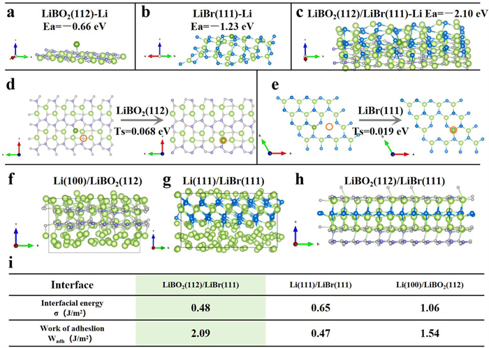
According to the theoretical calculation of the internal and external interfaces, the transport behaviors of lithium ions in the LiBO2-LiBr-Li electrode was analyzed as Fig. 3a. As calculated, adsorption energy for Li+ at interface of LiBO2(112)/LiBr(111) is 2.10 eV, much higher than that of LiBr(111) of 1.23 eV and LiBO2(112) of 0.66 eV (Figs. 3a-c). The greater affinity of the LiBO2/LiBr interface to Li+ leads to the formation of negatively charged centers [40, 41]. This facilitates the uniform distribution of Li+ within SEI, ensuring uniform Li deposition. Figs. 3d and e depicted the Li diffusion barriers between adjacent sites on the (112) plane of LiBO2 and (111) plane of LiBr, respectively. The Li+ diffusion barriers of LiBO2(112) and LiBr(111) are 0.068 eV and 0.019 eV, respectively, with small values, suggesting that Li+ can efficiently diffuse in SEI. Meanwhile, we carried out electrochemical impedance spectroscopy of two types of symmetric cells to study the ion transport behavior on the interphase. According to the Nyquist plots (Fig. S9 in Supporting information), the diameter of the semicircle at the high-frequency region represents the interface resistance of SEI formation (Rf). Through the comparison of impedance figures, we can clearly tell apart that the Rf of the cells is LiBO2-LiB-Li < Pristine Li. This indicates that the ionic conductivity of the hybrid SEI layer is higher than using Pristine Li, which is beneficial to improve the cycling performance of the cells. In order to assess the ability of the interface to inhibit lithium dendrite formation, calculations were performed to determine the interfacial energies and works of adhesion of different interfaces (Figs. 3f-i). The results show that the LiBO2(112)/LiBr(111) heterogeneous interface has the lowest interfacial energy (0.48 J/m2) and highest work of adhesion (2.09 J/m2), effectively mitigating the contact loss during Li stripping [42]. Supported by analysis, the conversion of the uneven Li2O layer into an inorganic SEI can significantly inhibit dendrite formation and facilitate the uniform deposition of lithium ions. This ultimately attributes to improved electrochemical performance of lithium metal batteries (LMBs).
Figure 3
Figure 3.
DFT calculations: the adsorption energies of (a) LiBO2(112), (b) LiBr(111), and (c) LiBO2(112)/LiBr(111). The calculation of (d) LiBO2(112) and (e) LiBr(111) diffusion barriers. Optimized structure of interfacial supercell model for (f) Li(100)/LiBO2(112) bulk-phase interface, (g) Li(111)/LiBr(111) interface, and (h) LiBO2(112)/LiBr(111) interface. (i) The calculated interfacial energy (σ) and the work of adhesion (Wadh) for the interfacial supercells.
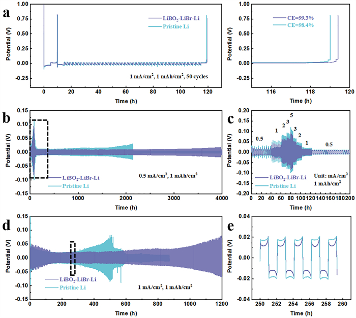
Furthermore, to evaluate the capacity retention and stability of different electrodes, we tested the coulombic efficiency (CE) of different cell systems after long-term plating/stripping process at 1 mA/cm2@1 mAh/cm2 (Fig. 4a). The corresponding Li plating/stripping voltage curves and the enlarged detail of the capacity retention by a final Li stripping process demonstrate that LiBO2-LiBr-Li//Cu cells show the higher CE of 99.3%, superior to pristine Li//Cu (98.4%) counterpart at a current of 1.0 mA/cm2, suggesting that the LiBr-LiBO2-enriched SEI is beneficial for enhancement of cycling stability. As for the high-rate performance of the anodes (Figs. 4b and c), the voltage polarizations of LiBO2-LiBr-Li anode are 19.4, 39.2, 59.2, 70.6, and 90.4 mV at current densities of 0.5, 1, 2, 3, and 5 mA/cm2, respectively, superior to those of pristine Li anodes. When return to the low current densities the voltage polarizations of LiBO2-LiBr-Li symmetric cells maintain well. Such a great stability enhancement is definitely stemmed from a more stable SEl, verifying that the implantation of LiBO2-LiBr SEI layer significantly enhances the kinetics of Li ions interfacial transport. In contrast, the pristine Li based symmetric cells displayed substantially larger overpotentials at high current densities due to the difficulty of the native SEI layer to meet the demands of fast Li ions transport.
Figure 4
Figure 4.
(a) Constant current charges and discharge curves at 1 mA/cm2@1 mAh/cm2 for 50 cycles to calculate average CE. (b) Rate performance and cycling stabilities at 0.5 mA/cm2@1 mAh/cm2. (c) Rate performance. (d) Cycling stability at 1 mA/cm2@1 mAh/cm2. (e) Partial enlarged details of voltage profiles.
Moreover, in long-term cycling measurements at 0.5 mA/cm2, the pristine Li anode without an artificial SEI layer performs stably for only 2000 h with an increased overpotential after 1500 h. In contrast, the symmetric cell assembled by LiBO2-LiBr-Li anode possesses a prolonged cycling life for 3500 h with a small voltage hysteresis of 14.6 mV, indicating enhanced cycling stability by LiBO2-LiBr SEI layer. Then, the cycling performance at higher current density and areal capacity were measured to further illustrate the superiority of the advanced electrode (Figs. 4d and e). The LiBO2-LiBr-Li anode performs an impressive cycling life for 1200 h with a stable voltage hysteresis of 20 mV at 1 mA/cm2@1 mAh/cm2, better than pristine Li (400 h). Meanwhile, compared with the performance of lithium metal batteries with similar SEI compositions in reported literature (Table S1 in Supporting information), the performance of symmetric LiBO2-LiBr-Li batteries in this work is also outstanding (Table S1). To further evaluate the efficacy of this approach, we also treated the thin 50 µm Li foil by BBr3 Plasma (Fig. S10a in Supporting information). The morphological and structural features of the artificial interphase can be obtained from SEM images. The SEI layer shows a dense surface (Figs. S10b and c in Supporting information). And energy dispersive spectroscopy (EDS) mapping of the interphase layer show even distribution of Br, B, and O elements (Figs. S10d-f in Supporting information), confirming the successfully establishment of a LiBO2/LiBr artificial SEI. Meanwhile, the 50 µm LiBO2-LiBr-Li shows a stable cycling performance and a low overpotential at 1.0 mA/cm2@1.0 mAh/cm2 (Fig. S11 in Supporting information). These results confirm the effectiveness of BBr3 Plasma method.
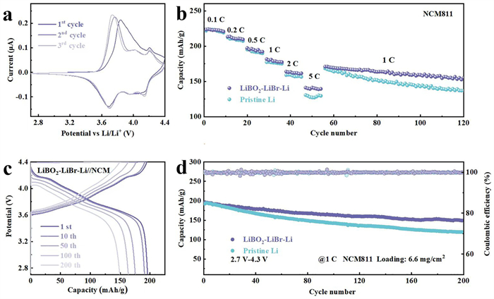
Finally, to demonstrate the practical application of modified nodes, the full cell paired with NCM811 cathode was assembled to evaluate the electrochemical performance. The areal mass load of NCM811 active material was about 6.6 mg/cm2 with a diameter of 15 mm (1 C = 275 mAh/g), while thickness of anode is 100 µm. And, the N/P of LiBO2-LiBr-Li||NCM is 4.3. Fig. 5a shows the cyclic voltammetry (CV) curves of full cells with LiBO2-LiBr-Li anodes at a scan rate of 0.1 mV/s. After activation at the first cycle, the CV curve becomes stable with overlapped peak potentials, suggesting good electrochemical reversibility and stability. The rate performance of LiBO2-LiBr-Li//NCM811 is shown in Fig. 5b, which delivers average discharge capacities of 222.6, 210.7, 194.9, 177.6, 161.9 and 140.3 mAh/g at C-rates of 0.1, 0.2, 0.5, 1, 2 and 5 C, respectively, while the pristine Li anode delivers discharge capacities of 222.3, 210.7, 190.4, 171.4, 152.2 and 125.4 mAh/g at the same C-rates, respectively. The superior rate performance of the LiBO2-LiBr-Li//NCM811 cell can be attributed to the highly reversible Li plating/stripping behaviors, and efficient ion/electron transfer kinetics. Fig. 5c shows the voltage profiles of the full cells assembled by LiBO2-LiBr-Li or bare anodes at 1st, 10th, 50th, 100th, and 200th cycles. Impressively, as the cycle number increases, the polarization gap of the Li//NCM811 cells significantly increases, compared with LiBO2-LiBr-Li//NCM811 (Fig. S12 in Supporting information). As for the long-term cycling process (Fig. 5d), the LiBO2-LiBr-Li//NCM811 cell delivers a specific capacity of 149.6 mAh/g after 200 cycles with a capacity retention of 78.0% at 1 C, higher than 61.8% capacity retention of pristine Li. These results demonstrate excellent rate performance and cycling stability of cells with LiBO2-LiBr-Li anodes, indicating the great potentials for practical application.
Figure 5
Figure 5.
Electrochemical performance of cells paired with NCM811 cathode: (a) Cyclic voltammogram at a scan rate of 0.1 mV/s. (b) Rate performance. (c) Selected charging/discharging profile of LiBO2-LiBr-Li full cells in (d) cycling stability at 1 C.
In summary, a new liquid plasma BBr3 strategy is firstly proposed to converse the native oxide layer into a high-grade inorganic solid electrolyte interphase, dominated by LiBr-LiBO2, for optimization of Li-metal anodes. This well-designed SEI withs low interfacial energy and high work of adhesion SEI can strengthen mechanical property, thus suppressing dendrite growth and preventing interfacial penetration. Meanwhile, the intrinsic properties of the protective layer attribute to improved Li+ transport kinetics and homogeneous Li+ deposition. Beneficial from these advantages, the as-designed LiBO2-LiBr-Li exhibits considerable cycling stability over 1100 h at a current density of 1 mA/cm2. The fully assembled cell with a high-voltage LiNi0.8Co0.1Mn0.1O2 cathode also displays long-life stability with capacity retention (78% after 200 cycles) at 1 C and excellent rate performance. This work proposes a new liquid plasma BBr3 strategy for the manufacture of an inorganic protective SEI on the surface of metal anodes, thus facilitating the commercialization process of high-energy density metal batteries.
Declaration of competing interest
The authors declare that they have no known competing financial interests or personal relationships that could have appeared to influence the work reported in this paper.
This work is supported by National Natural Science Foundation of China (Nos. 52372235, 52073252, 52002052, U20A20253, 21972127, 22279116), Key Scientific Research Project of Hangzhou (No. 2024SZD1B12); Science and Technology Department of Zhejiang Province (Nos. 2023C01231, Q23E020046, LD22E020006, and LY21E020005), Key Research and Development Project of Science and Technology Department of Sichuan Province ((No. 2022YFSY0004), Natural Science Foundation of Zhejiang Province (No. LQ23E020009), Sichuan Natural Science Foundation project (No. 2024NSFSC0951) and Key Laboratory of Engineering Dielectrics and Its Application (Harbin University of Science and Technology), Ministry of Education (No. KFM 202303).
Supplementary materials
Supplementary material associated with this article can be found, in the online version, at doi:10.1016/j.cclet.2024.110753.
[1]
H. Zhang, C. Li, G.G. Eshetu, et al., Angew. Chem. Int. Ed. 59 (2020) 534–538. doi: 10.1002/anie.201913923
[2]
L. Huang, S. Shen, Y. Zhong, et al., Adv. Mater. 34 (2022) e2107415.
[3]
W. Wu, W. Luo, Y. Huang, Chem. Soc. Rev. 52 (2023) 2553–2572. doi: 10.1039/d2cs00606e
[4]
N.W. Li, Y. Shi, Y.X. Yin, et al., Angew. Chem. Int. Ed. 57 (2018) 1505–1509. doi: 10.1002/anie.201710806
[5]
Q. Wang, T. Lu, Y. Xiao, et al., Electrochem. Energy Rev. 6 (2023) 22. doi: 10.47298/jala.v5-i1-a2
[6]
Z. Yu, Y. Cui, Z. Bao, Cell Rep. Phys. Sci. 1 (2020) 100119.
[7]
S. Shen, Y. Chen, J. Zhou, et al., Adv. Energy Mater. 13 (2023) 2204259.
[8]
S. Shen, Y. Chen, X. Gu, et al., Adv. Mater. 36 (2024) e2400245.
H. Duan, Y. You, G. Wang, et al., Nanomicro. Lett. 16 (2024) 78.
[16]
C.H. Zhang, T. Jin, J. Liu, et al., Small 19 (2023) e2301523.
[17]
Z. Wang, J. Xue, Z. Song, et al., Chin. Chem. Lett. 35 (2024) 109489.
[18]
B. Jagger, M. Pasta, Joule 7 (2023) 2228–2244.
[19]
B. Liu, Y. Zhang, Z. Wang, et al., Adv. Mater. 32 (2020) e2003657.
[20]
S. Liu, X. Ji, N. Piao, et al., Angew. Chem. Int. Ed. 60 (2020) 3661–3671. doi: 10.1002/qj.3865
[21]
P. Liu, H. Su, Y. Liu, et al., Small Struct. 3 (2022) 2200010.
[22]
Z. Ju, X. Tao, Y. Wang, et al., Energy Environ. Sci. 17 (2024) 4703–4713. doi: 10.1039/d4ee01359j
[23]
C. Wu, H. Huang, W. Lu, et al., Adv. Sci. 7 (2020) 1902643.
[24]
D. Han, Z. Wang, S. Chen, et al., Small 20 (2024) e2405453.
[25]
J. Zhu, D. Cai, J. Li, et al., Energy Storage Mater. 49 (2022) 546–554.
[26]
H. Zhuang, H. Xiao, T. Zhang, et al., Angew. Chem. Int. Ed. 63 (2024) e202407315.
[27]
W. Cao, J. Lu, K. Zhou, et al., Nano Energy 95 (2022) 106983.
[28]
L. Zhang, D. Dong, A. Cresce, et al., Energy Storage Mater. 69 (2024) 103397.
[29]
H. Wang, J. Liu, G. Jiang, et al., Adv. Energy Mater. 14 (2024) 2400067.
[30]
W. Cao, W. Chen, M. Lu, et al., J. Energy Chem. 76 (2023) 648–656.
[31]
X. Yao, J. Wang, S. Lin, et al., Adv. Energy Mater. 13 (2022) 2203233.
[32]
P. Liu, Z. Qiu, F. Cao, et al., J. Mater. Sci. Technol. 177 (2024) 68–78.
[33]
M. Baek, J. Kim, K. Jeong, et al., Nat. Commun. 14 (2023) 1296.
[34]
L. Li, K. Yang, C. Xi, et al., Chin. Chem. Lett. 35 (2024) 108814.
[35]
P. Qing, S. Huang, T. Naren, et al., Sci. Bull. 69 (2024) 2842–2852.
[36]
P. Liu, S. Shen, Z. Qiu, et al., Adv. Mater. 36 (2024) 2312812.
[37]
T. Deng, X. Fan, L. Cao, et al., Joule 3 (2019) 2550–2564.
[38]
X. Hu, Y. Ma, J. Qian, et al., Adv. Mater. 36 (2024) e2303710.
[39]
A. Mauger, M. Armand, C.M. Julien, K. Zaghib, J. Power Sources 353 (2017) 333.
[40]
Y. Yu, G. Huang, J.Z. Wang, et al., Adv. Mater. 32 (2020) e2004157.
[41]
D. Wu, J. He, J. Liu, et al., Adv. Energy Mater. 12 (2022) 2200337.
[42]
A. Hu, W. Chen, X. Du, et al., Energy Environ. Sci. 14 (2021) 4115. doi: 10.1039/d1ee00508a
Figure 1
(a) Diagram of the synthesis process of LiBO2-LiBr-Li. (b) SEM images of Pristine Li (embedded picture: optical photo). (c) SEM images and (d) Cross-sectional SEM image of LiBO2-LiBr-Li. (e-g) Scanning electron microscopy image of LiBO2-LiBr-Li and the corresponding elemental maps of Br, and B.
Figure 2
(a-c) HRTEM images of LiBO2-LiBr-Li. XPS spectra of (d) Li 1s, (e) Br 3d, and (f) B 1s for LiBO2-LiBr-Li at different etching levels. (g) The Young's modulus mapping of LiBO2-LiBr-Li. (h, i) SEM images of pristine Li, and LiBO2-LiBr-Li anodes after 50 cycles at 1 mA/cm2@1 mAh/cm2. (j) In situ optical microscopy images of LiBO2-LiBr-Li symmetric cells at 10 mA/cm2.
Figure 3
DFT calculations: the adsorption energies of (a) LiBO2(112), (b) LiBr(111), and (c) LiBO2(112)/LiBr(111). The calculation of (d) LiBO2(112) and (e) LiBr(111) diffusion barriers. Optimized structure of interfacial supercell model for (f) Li(100)/LiBO2(112) bulk-phase interface, (g) Li(111)/LiBr(111) interface, and (h) LiBO2(112)/LiBr(111) interface. (i) The calculated interfacial energy (σ) and the work of adhesion (Wadh) for the interfacial supercells.
Figure 4
(a) Constant current charges and discharge curves at 1 mA/cm2@1 mAh/cm2 for 50 cycles to calculate average CE. (b) Rate performance and cycling stabilities at 0.5 mA/cm2@1 mAh/cm2. (c) Rate performance. (d) Cycling stability at 1 mA/cm2@1 mAh/cm2. (e) Partial enlarged details of voltage profiles.
Figure 5
Electrochemical performance of cells paired with NCM811 cathode: (a) Cyclic voltammogram at a scan rate of 0.1 mV/s. (b) Rate performance. (c) Selected charging/discharging profile of LiBO2-LiBr-Li full cells in (d) cycling stability at 1 C.

 DownLoad:

 下载:
下载:


