Scheme 1.
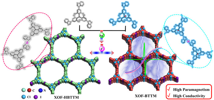
The construction of [N···I···N]+-bridged XOF-HBTTM/BTTM.
Construction of radical halogen-bonded organic frameworks with enhanced magnetism and conductivity
Hong-Qiang Dong , Shang-Bo Yu , Shu-Meng Wang , Jia-Hao Zhao , Xu-Guan Bai , Shi-Xing Lei , Zhen-Nan Tian , Jia Tian , Kang-Da Zhang , Lu Wang , Zhan-Ting Li , Shigui Chen

Characterized by unpaired electrons, organic radicals possess low-lying doubly excited states, redox amphotericity, and narrow HOMO-LUMO energy gaps, offering a wealth of potential applications in electronics, photonics, spintronics, organic catalysis, and energy storage [1–4]. Among these, multiple radicals may provide enhanced magnetic properties and tunable conductivities [5,6], and they might also result in cooperative applications in catalysis and energy storage due to the synergistic effects of the multiple radicals [7–9]. However, due to their open-shell and subvalent features, as well as their intrinsic thermodynamic and kinetic instability, organic radicals generally exhibit high reactivity [10–12]. This reactivity leads to the formation of covalent bonds through dimerization, disproportionation, or hydrogen abstraction, making it difficult to create polyradicals [13,14]. Nevertheless, achieving multiple radicals, especially in highly ordered arrangements in long-range domains is still challenging.
Over the past decades, organic frameworks, constructed through covalent bonds and non-covalent interactions, have emerged as a novel family of orderly porous materials, allowing for molecular-level design of highly periodic atomic structures [15–19]. Their permanent porosity, diverse morphologies, and tunable functionalities have made them attractive candidates for various applications, such as gas storage [20–22], catalysis [23,24], energy conversion and storage [25–27], organic electronics [28,29], and more. Due to the modifications, organic frameworks might serve as an excellent platform for constructing multiple radical structures in highly ordered arrangements by incorporating organic radicals into their structures. The main strategies for introducing organic radicals into organic frameworks include post-functionalization, which involves attaching radical-containing motifs to the sides of preconstructed organic framework skeletons with active groups [7,30–32]. The radical groups are then attached to the framework skeletons via flexible single bonds, which may affect the crystallinity of the frameworks. Another strategy is to construct organic frameworks with radical skeletons by employing well-designed radical monomers [33–35]. The unpaired electrons may delocalize among the frameworks through conjugated systems, enhancing the stability of the radicals and potentially introducing new properties and functions [36]. Although a few examples of organic frameworks with radical skeletons have been reported, the results have been far from satisfactory. Therefore, new strategies are still required for the construction of organic frameworks with radical skeletons.
Halogen bonds (XB) are non-covalent interactions arising from the electrostatic attraction between an electron-deficient halogen atom and a Lewis base [37–39]. Featured by its directionality, halogen bonds have found applications in diverse fields, including molecular machines [40,41], anion recognition [42,43], crystal engineering [44,45], and catalysis [46,47]. Beyond traditional halogen bonds, the removal of an electron from the halogen atom forms a positively charged X+ species, featuring a p-hole that form unique three-center-four-electron [N···I···N]+ halogen bonds with two Lewis bases simultaneously [48,49]. This type of XB has serves as ideal building blocks for supramolecular assemblies, leading to diverse structures such as supramolecular capsules [50,51], cages [52], and macrocyclic complexes [53]. Recently, [N···I···N]+ halogen bonds have been utilized to construct a novel class of halogen-bonded organic frameworks (XOFs) [54,55], leading to potential applications in areas like adsorption [56–58], halogenation reactions [59], and catalysis [60]. Due to their structural diversity and stability [61,62], XOFs provide an excellent platform for constructing radical skeleton organic frameworks. tris(2,4,6-trichlorophenyl)methyl (TTM) radicals, known for their high stability due to the presence of three bulky polychlorophenyl groups, are employed in preparing radical monomers [63]. However, the polychloride groups decrease the reactivity of polychlorophenyl motifs, leading to challenges in introducing pyridyl groups via Suzuki coupling (Scheme S2 in Supporting information). To address this issue, benzimidazole was used to couple with polychlorotriphenylmethane (Scheme S3 in Supporting information).
In this study, we describe the construction of a novel type of two-dimensional radical halogen-bonded organic frameworks. Benzimidazole-modified monomer (HBTTM/BTTM) was synthesized from tri(2,4,6-trichlorophenyl)methyl (TTM) and benzimidazole monomer (Scheme 1). The benzimidazole units were coordinated with Ag+ to form a precursor MOF, which was then converted into the target XOF through an in situ cation exchange process, replacing Ag+ with I+ to generate [N···I···N]+ halogen bonds. XOF-HBTTM and XOF-BTTM demonstrated good crystallinity, as evidenced by PXRD, HR-TEM, SEAD, and SAXS analyses. Importantly, EPR measurements confirmed the preservation of radical character within the XOF framework. SQUID measurements revealed that XOF-BTTM exhibits spin moments of S = 1/2 at 2 K, with a saturated magnetization strength peaking at 4.10 emu/g, compared to a saturation magnetization intensity of 1.87 emu/g for the monomer BTTM. DFT calculations suggest that the extended spin density distribution and the presence of [N···I···N]+ interactions within the XOF framework likely contribute to this enhanced magnetism. The conductivity of the radical XOF-BTTM reached up to 1.30 × 10⁻⁴ S/cm, a two-order-of-magnitude increase over that of non-radical counterpart, XOF-HBTTM. The carrier mobility of the radical XOF-BTTM was also improved. This enhancement is attributed to the reduced HOMO-LUMO gap, higher carrier density, and the presence of triphenylmethyl radicals within the framework. This work not only demonstrates the potential of benzimidazolyl motifs for constructing functional XOFs but also provides valuable insights into the structure-property relationships of radical-containing organic frameworks.
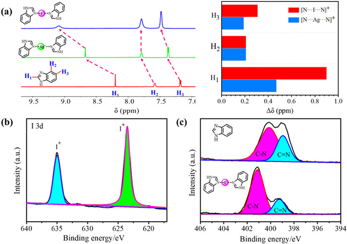
To investigate the feasibility of [N···I···N]+ halogen bonds between imidazole and with iodine(I), a series of experiments were carried out using benzoimidazole (BIa) and N-phenylbenzimidazole (pH-BIa) as model molecules. The model iodine(I) complexes BIa2IBF4 and pH-BIa2IBF4 were prepared through the in situ [N···Ag···N]+→[N···I···N]+ cationic substitution method, as previously reported (see Supporting information for details) [54]. The formation of the iodine(I) complexes was firstly monitored by 1H NMR spectra. The H1/2/3 signal peaks of BIa2AgBF4 and BIa2IBF4 complex showed distinct downfield shifts in comparison to those of free BIa (ΔδH1 = 0.47, ΔδH2 = 0.21, and ΔδH3 = 0.19 ppm for BIa2AgBF4, ΔδH1 = 0.90, ΔδH2 = 0.21, and ΔδH3 = 0.31 ppm for BIa2IBF4). These downfield shifts are attributed to the coordination of imidazole with Ag+/I+, which reduces electron density of imidazole, leading to a deshielding effect in the local magnetic environments (Fig. 1a). Notably, the BIa2IBF4 complex gave larger shifts than those of the BIa2AgBF4 complex, implying the formation of strong halogen bonds among BIa2IBF4. Similar downfield shifts were observed for pH-BIa2IBF4 compared to pH-Bia (Fig. S9a in Supporting information). The chemical states of the surface of BIa2IBF4 and pH-BIa2IBF4 were further analyzed by X-ray photoelectron spectroscopy (XPS). The XPS spectrum of BIa2IBF4 shows two sets of signals, ascribed to I 3d3/2 (623.49 eV) and I 3d5/2 (634.99 eV) of I+, respectively (Fig. 1b) [64]. The binding energy of the -C = N bond in XPS increased, indicating a lowered electron density around the nitrogen, further supporting the formation of [N···I···N]+ complexes (Fig. 1c). Similar observations of I+ signals and N environment shifts were found in the XPS analysis of pH-BIa2IBF4 (Figs. S9b and c in Supporting information). Fourier transform infrared (FT-IR) spectroscopy provided further evidence for complex formation. The peak corresponding to -C=N vibrations exhibited red-shift with the formation of iodine(I) complexes (BIa shifted from 1590 cm−1 to 1611 cm−1, pH-BIa shifted from 1595 cm−1 to 1612 cm−1). This red-shift implied the decrease in electron density of the imidazole ring, consistent with coordination between imidazole groups and I+, confirming the formation of [N···I···N]+ complexes (Fig. S11 in Supporting information).
The tris(2,4,6-trichlorophenyl)methyl (TTM) radical exhibits high stability due to the protective and resonance effects of the surrounding polychlorinated phenyl units. Benzimidazolyl groups were introduced to the end of TTM to give tribenzimidazolyl triphenylmethane (HBTTM) for the exploration of 2D XOFs. HBTTM was synthesized and characterized according to the reported procedure (Scheme S3 in Supporting information) [65]. HBTTM was further deprotonated with Bu4NOH and oxidated tetrachloro-p-benzoquinone (TCBQ) to give the radical BTTM (Scheme S4 in Supporting information). Density functional theory (DFT) calculations were performed to optimize the ground-state geometry structures and obtain electrostatic potential (ESP) maps of HBTTM and BTTM (Fig. S13 in Supporting information). The ESP map of HBTTM/BTTM revealed distinct red regions around the exposed imidazole N atoms, indicating strong negative electronegativity. This electronic structure makes them efficient electron donors for Ag+ and I+ to form coordination and halogen bonds. Meanwhile, the spin density was primarily distributed across the tris(2,4,6-trichlorophenyl)methyl group for BTTM.
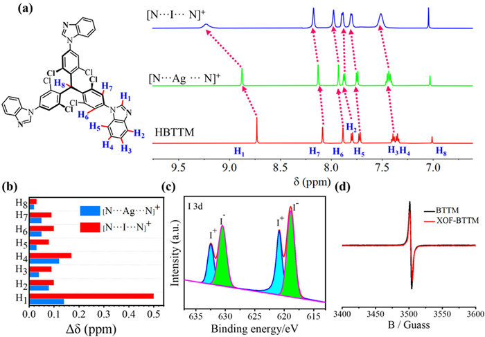
Following the procedure we reported earlier, HBTTM/BTTM was first coordinated with Ag+ to construct MOF-HBTTM/BTTM based on [N···Ag···N]+ interactions [54]. Subsequently, an in situ cation exchange reaction involving [N···Ag···N]+→[N···I···N]+ was employed to prepare XOF-HBTTM/BTTM. The formation of XOF-HBTTM was firstly investigated by 1H NMR spectra. In the 1H NMR spectra (Fig. 2a), the aromatic proton signals (H1—H7) of XOF-HBTTM display a large deshielded effect compared with the HBTTM ligand (ΔδH1 = 0.49, ΔδH2 = 0.10, ΔδH3 = 0.09, ΔδH4 = 0.17, ΔδH5 = 0.08, ΔδH6 = 0.10 and ΔδH7 = 0.09 ppm, respectively), which attributed to the electron density decrease of imidazole groups during the coordination with I+. The surface chemical states of XOF-HBTTM/BTTM were analyzed by XPS (Fig. 2c and Fig. S14a in Supporting information). The peaks, attributed to I+, were observed at 620.27 eV (I 3d3/2) and 632.79 eV (I 3d5/2) for XOF-HBTTM, 620.89 eV (I 3d3/2) and 632.49 eV (I 3d5/2) for XOF-BTTM, respectively. The other peaks were attributed to I− in AgI species [66,67]. The IR spectra revealed a red shift in the -C=N stretching vibration from 1715 cm−1 in HBTTM to 1726 cm−1 in XOF-HBTTM (Fig. S15a in Supporting information), indicating coordination of the imidazole nitrogens with I+. Similar red shifts were observed for XOF-BTTM (Fig. S15b in Supporting information). The electron paramagnetic resonance (EPR) experiments gave absorption signals for both BTTM and XOF-BTTM (Fig. 2d), indicating the presence of triphenylmethyl(trityl) radicals. The g-factor values (g = 2.0033/2.0035) obtained were consistent with previously reported values for trityl radicals [68]. EPR measurement was further performed in the solid state (Fig. S16 in Supporting information), implying the stability of the radicals after the formation and annealing of the XOFs. What is more, Dynamic light scattering (DLS) experiments revealed that the hydrodynamic diameters (DH) of XOF-HBTTM and XOF-BTTM in the polar solvent DMSO were measured to be approximately 300 nm and 1100 nm, respectively (Fig. S17 in Supporting information), which are significantly larger than those of the monomer HBTTM/BTTM (around 10 nm). This dramatic increase in size is consistent with the formation of the proposed 2D framework structures.
Powder X-ray diffraction (PXRD) analysis was employed to evaluate the crystalline structures of XOF-HBTTM and XOF-BTTM. The Forcite molecular dynamics module method and Pawley refinement in Materials Studio was utilized for structural elucidation. Eclipsed (AA) and staggered (AB) stacking models were constructed for XOF-HBTTM and XOF-BTTM using the Forcite module. The simulated PXRD pattern based on the AA stacking model exhibited good agreement with the experimental patterns for both XOFs (Fig. S20 in Supporting information). Pawley refinement of the experimental PXRD pattern for XOF-HBTTM yielded a unit cell with parameters of a = 33.56 Å, b = 34.08 Å, c = 14.89 Å, α = β = 90°, γ = 120° (Rwp = 3.33%, Rp = 1.66%) (Fig. 3a). The corresponding PXRD pattern displayed characteristic peaks at 2θ = 6.74°, 8.51°, and 10.07°, assigned to the (101), (220), and (400) crystal planes, respectively. Similarly, XOF-BTTM exhibited PXRD peaks at 2θ = 6.71° and 8.50°, corresponding to (101) and (220) reflections (Fig. 3d). Pawley refinement resulted in a unit cell with parameters of a = 33.45 Å, b = 33.97 Å, c = 14.35 Å, α = β = 90°, γ = 120° (Rwp = 4.05% and Rp = 1.96%) (Fig. 3d). Small-angle X-ray scattering (SAXS) analysis provided further evidence for the structural ordering of XOF-HBTTM and XOF-BTTM. The SAXS pattern of XOF-HBTTM displayed distinct peaks at q-values of 0.236, 0.259, 0.422, and 0.463 Å−1, corresponding to d-spacings of approximately 14.69, 13.14, 11.11, and 10.39 Å (Fig. 3b), which match well with the calculated spacings for the (
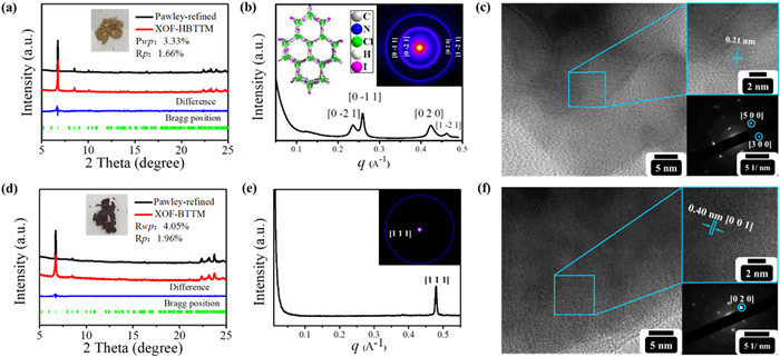
The morphologies of XOF-HBTTM and XOF-BTTM were investigated using transmission electron microscopy (TEM). High-resolution TEM (HR-TEM) further revealed distinct lattice fringes within both XOFs. XOF-HBTTM exhibited an interplanar spacing of 0.21 nm, while XOF-BTTM displayed a spacing of 0.40 nm. Selected area electron diffraction (SAED) provided further insights into the crystallographic structures. The SAED pattern of XOF-HBTTM displayed distinct diffraction spots corresponding to the (300) and (500) planes (Fig. 3c). Similarly, the SAED pattern of XOF-BTTM revealed diffraction spots attributable to the (020) plane (Fig. 3f). These observations implied the formation of periodic halogen-bond networks in the solid state for both XOFs, indicating high crystallinity. Energy-dispersive X-ray spectroscopy (EDS) elemental mapping confirmed the uniform distribution of carbon (C), nitrogen (N), iodine (I), and boron (B) within XOF-HBTTM and XOF-BTTM (Fig. S23 in Supporting information). The porosity of XOF-HBTTM and XOF-BTTM was investigated using N2 gas adsorption isotherms measured at 77 K (Fig. S24 in Supporting information). The Brunauer-Emmett-Teller (BET) surface areas were determined to be 9.82 and 19.34 m3/g for XOF-HBTTM and XOF-BTTM, respectively. The low porosity could be attributed to the presence of counterions (BF4−) and AgI.
The magnetic properties of the monomer radical BTTM and the radial framework XOF-BTTM were investigated by Superconducting quantum interference device (SQUID). Magnetization-applied field (M-H) and magnetic susceptibility-temperature (χ-T) curves were measured across a temperature range of 2–300 K. The M-H curve of the BTTM monomer measured at 2 K exhibited a rise in magnetization intensity, reaching saturation at a magnetic field of ±6 × 10⁴ Oe (Fig. S25 in Supporting information). The Brillouin function accurately described the M-H curve, with a saturation magnetization intensity of 1.87 emu/g. The χ-T plot displayed a characteristic increase in susceptibility with decreasing temperature, confirming paramagnetic behavior (Fig. S26 in Supporting information). XOF-BTTM exhibited a higher magnetization intensity compared to BTTM (Fig. 4a). The saturation magnetization intensity of XOF-BTTM was 4.10 emu/g, approximately 2.2 times greater than that of BTTM. Brillouin function fitting suggested the presence of J = S = 1/2 spin states in XOF-BTTM, indicating nearly independent paramagnetic behavior of the radicals within the framework (Fig. S27 in Supporting information). The temperature-dependent susceptibility plot (χ-T) further corroborated the paramagnetic nature of XOF-BTTM (Fig. 4b). The block magnetic susceptibility also displayed a linear relationship with 1/T, supporting its paramagnetic character. Notably, the susceptibility of XOF-BTTM was 1.4 times higher than that of BTTM, with a calculated molar susceptibility of 7396 emu/mol.
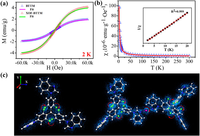
Density functional theory (DFT) calculations were performed to understand the variations in magnetic properties between BTTM and XOF-BTTM. The spin density distribution (Fig. S29 in Supporting information) revealed the distribution of unpaired electrons in both materials. In BTTM, most unpaired electrons were localized on the TTM-radical moiety, particularly on the central carbon atom. In contrast, the spin density distribution in XOF-BTTM extended to the imidazole nitrogen atoms due to iodine(I) bridged [N···I···N]+ halogen bonds, indicating enhanced conjugation within the framework. This extended conjugation likely reduces the orbital energy gap in XOF-BTTM, facilitating electron transfer. Furthermore, the magnetic moment analysis showed a decrease in the carbon radical moment (0.53 µB to 0.51 µB) and an increase in the nitrogen moment (0.0055 µB to 0.03/0.0011 µB) upon the formation of XOF-BTTM. Additionally, a magnetic moment of 0.0023 µB was observed for iodine, suggesting magnetic-exchange interactions between the [N···I···N]+ halogen bonds. Magnetic induction current simulations revealed a denser current coil in XOF-BTTM compared to BTTM (Fig. 4c), further supporting the enhanced magnetic behavior in XOF-BTTM.
The reduction of the orbital energy gap facilitate the electron transfer in radical BTTM, which may promote their conductivity. The electrical properties of XOF-HBTTM and XOF-BTTM were further investigated. Electrical conductivity measurements were performed using the four-probe technique on pressed powder pellets under ambient conditions, revealing a significant difference between the XOFs. While XOF-HBTTM exhibited a conductivity of 7.83 × 10⁻⁶ S/cm, XOF-BTTM displayed a remarkably high conductivity of 1.30 × 10⁻⁴ S/cm, representing a significant two-order-of-magnitude increase (Fig. 5a). XOF-BTTM's conductivity surpasses the typical range (10−14 – 10−5 S/cm) observed for most 2D conductive materials [69], implying its potential electronic applications. Hall effect measurements further supported the superior charge transport properties of XOF-BTTM. The carrier volume density in XOF-BTTM (3.81 × 109 cm−3) was nearly 19 times more than that of XOF-HBTTM (2.03 × 108 cm−3) (Fig. S30 and Table S2 in Supporting information). Similarly, XOF-BTTM exhibited a higher carrier mobility (4.11 cm2 V−1 s−1) compared to XOF-HBTTM (1.17 cm2 V−1 s−1) (Fig. 5b).
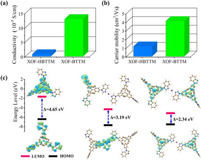
Density functional theory (DFT) calculations were performed to understand the differences in conductivity between the frameworks. The analysis of frontier orbitals (HOMO and LUMO) revealed a reduced HOMO-LUMO gap for both XOFs compared to the precursor HBTTM. This suggests more delocalized frontier orbitals within the frameworks, facilitating electron movement and charge transfer within the frameworks. Notably, XOF-BTTM exhibited a further reduction in the band gap (from 3.19 eV to 2.34 eV) compared to XOF-HBTTM (Fig. 5c). This significant decrease in the band gap likely contributes to the enhanced conductivity and charge transport in XOF-BTTM. The presence of triphenylmethyl radicals in XOF-BTTM contributes to a higher electron population, leading to increased carrier density and mobility.
In conclusion, we demonstrated the construction of a novel type of radical two-dimensional halogen-bonded organic frameworks, XOF-BTTM. Benzimidazolyl groups were incorporated into the stable tris(2,4,6-trichlorophenyl)methyl radical to facilitate the formation of robust [N···I···N]+ halogen bonds. XOF-BTTM were fabricated by incorporating benzimidazolyl groups to a stable tris(2,4,6-trichlorophenyl)methyl radical to facilitate the formation of [N···I···N]+ halogen bonds. The radical character was remarkably preserved upon XOF formation. Both XOF-HBTTM/BTTM exhibit high crystallinity. XOF-BTTM exhibited significantly enhanced magnetic properties compared to BTTM, as evidenced by the higher saturation magnetization and susceptibility. DFT calculations revealed that the extended spin density distribution and the presence of [N···I···N]+ interactions within the XOF framework likely contribute to this improved magnetism. Furthermore, XOF-BTTM demonstrated a remarkable two-order-of-magnitude increase in electrical conductivity and improved carrier mobility compared to XOF-HBTTM. This enhancement is attributed to the reduced HOMO-LUMO gap, higher carrier density, and the presence of triphenylmethyl radicals within the framework. This work not only demonstrated the potential of benzimidazolyl motifs for the construction of functional XOFs, but also deepen our understanding of radical organic frameworks. These will be further leveraged for the design of advanced organic frameworks with tunable magnetic and electrical properties with potential applications in information storage and spintronic devices.
The authors declare that they have no known competing financial interests or personal relationships that could have appeared to influence the work reported in this paper.
Hong-Qiang Dong: Data curation, Formal analysis, Writing – original draft. Shang-Bo Yu: Methodology. Shu-Meng Wang: Software. Jia-Hao Zhao: Formal analysis. Xu-Guan Bai: Software. Shi-Xing Lei: Methodology. Zhen-Nan Tian: Visualization. Jia Tian: Resources. Kang-Da Zhang: Funding acquisition, Validation. Lu Wang: Resources. Zhan-Ting Li: Investigation. Shigui Chen: Conceptualization, Project administration, Supervision, Writing – review & editing.
This work was supported by National Natural Science Foundation of China (Nos. 22371218, 21702153, 52270070 and 21801194), Natural Science Foundation of Zhejiang Province (No. LR22B020001) and Wuhan Science and Technology Bureau (No. whkxjsj009). We thank the support of the Core Facility of Wuhan University and the Large-scale Instrument and Equipment Sharing Foundation of Wuhan University. We thank the support of Shanghai Synchrotron Radiation Facility.
Supplementary material associated with this article can be found, in the online version, at doi:
S. Kasemthaveechok, L. Abella, J. Crassous, et al., Chem. Sci. 13 (2022) 9833–9847. doi: 10.1039/d2sc02480b
Z.X. Chen, Y. Li, F. Huang, Chem 7 (2021) 288–332.
T. Kubo, M. Abe, Chem. Rev. 124 (2024) 4541–4542. doi: 10.1021/acs.chemrev.3c00893
D. Maspoch, N. Domingo, D. Ruiz-Molina, et al., Angew. Chem. Int. Ed. 43 (2004) 1828–1832.
Y. Jiang, I. Oh, S.H. Joo, et al., ACS Nano 13 (2019) 5251–5258. doi: 10.1021/acsnano.8b09634
I. Ratera, J. Veciana, Chem. Soc. Rev. 41 (2012) 303–349.
K.Q. Hu, Z.W. Huang, X.B. Li, et al., Adv. Funct. Mater. 33 (2023) 2213039.
F. Chen, X. Guan, H. Li, et al., Angew. Chem. Int. Ed. 60 (2021) 22230–22235. doi: 10.1002/anie.202108357
F. Xu, H. Xu, X. Chen, et al., Angew. Chem. Int. Ed. 54 (2015) 6814–6818. doi: 10.1002/anie.201501706
M.P. Sibi, C. Li, N. Jiao, Sci. China Chem. 62 (2019) 1423–1424. doi: 10.1007/s11426-019-9643-y
A. Bhunia, A. Studer, Chem 7 (2021) 2060–2100.
M. Mas-Torrent, N. Crivillers, C. Rovira, J. Veciana, Chem. Rev. 112 (2012) 2506–2527. doi: 10.1021/cr200233g
B. Tang, J. Zhao, J.F. Xu, X. Zhang, Chem. Sci. 11 (2020) 1192–1204. doi: 10.1039/c9sc06143f
J. Sun, Z. Liu, W.G. Liu, et al., J. Am. Chem. Soc. 139 (2017) 12704–12709. doi: 10.1021/jacs.7b06857
K.T. Tan, S. Ghosh, Z. Wang, et al., Nat. Rev. Methods Primers 3 (2023) 1–19.
X. Feng, X. Ding, D. Jiang, Chem. Soc. Rev. 41 (2012) 6010–6022. doi: 10.1039/c2cs35157a
J. Zhang, W. Kosaka, Y. Kitagawa, H. Miyasaka, Nat. Chem. 13 (2021) 191–199. doi: 10.1038/s41557-020-00577-y
R.B. Lin, Y. He, P. Li, et al., Chem. Soc. Rev. 48 (2019) 1362–1389. doi: 10.1039/c8cs00155c
B. Yang, S.B. Yu, P.Q. Zhang, et al., Angew. Chem. Int. Ed. 60 (2021) 26268–26275. doi: 10.1002/anie.202112514
J.R. Li, R.J. Kuppler, H.C. Zhou, Chem. Soc. Rev. 38 (2009) 1477–1504. doi: 10.1039/b802426j
J. Dong, X. Han, Y. Liu, et al., Angew. Chem. Int. Ed. 59 (2020) 13722–13733. doi: 10.1002/anie.202004796
C. Liu, C. Jia, S.X. Gan, et al., Chin. Chem. Lett. 35 (2024) 109750.
S.M.J. Rogge, A. Bavykina, J. Hajek, et al., Chem. Soc. Rev. 46 (2017) 3134–3184.
Q. Zhu, L. Wei, C. Zhao, et al., J. Am. Chem. Soc. 145 (2023) 23352–23360. doi: 10.1021/jacs.3c09246
H. Furukawa, O.M. Yaghi, J. Am. Chem. Soc. 131 (2009) 8875–8883. doi: 10.1021/ja9015765
S. Tao, D. Jiang, CCS Chem. 3 (2021) 2003–2024. doi: 10.31635/ccschem.020.202000491
S. Kandambeth, K. Dey, R. Banerjee, J. Am. Chem. Soc. 141 (2019) 1807–1822. doi: 10.1021/jacs.8b10334
N. Keller, T. Bein, Chem. Soc. Rev. 50 (2021) 1813–1845. doi: 10.1039/d0cs00793e
J. Guo, Y. Duan, Y. Jia, et al., Nat. Commun. 15 (2024) 139.
Y.Z. Cheng, W. Ji, X. Wu, et al., Appl. Catal. B: Environ. 306 (2022) 121110.
Q. Gu, X. Lu, C. Chen, et al., ACS Nano 17 (2023) 23903–23912. doi: 10.1021/acsnano.3c08313
Z. Mi, P. Yang, R. Wang, et al., J. Am. Chem. Soc. 141 (2019) 14433–14442. doi: 10.1021/jacs.9b07695
W. Cao, W.D. Wang, H.S. Xu, et al., J. Am. Chem. Soc. 140 (2018) 6969–6977. doi: 10.1021/jacs.8b02839
H. Li, J. Chang, S. Li, et al., J. Am. Chem. Soc. 141 (2019) 13324–13329. doi: 10.1021/jacs.9b06908
Y. Zhou, F. Yu, J. Su, et al., Angew. Chem. Int. Ed. 59 (2020) 18763–18767. doi: 10.1002/anie.202008941
L. Mao, M. Zhou, X. Shi, H.B. Yang, Chin. Chem. Lett. 32 (2021) 3331–3341.
G. Cavallo, P. Metrangolo, R. Milani, et al., Chem. Rev. 116 (2016) 2478–2601. doi: 10.1021/acs.chemrev.5b00484
L.C. Gilday, S.W. Robinson, T.A. Barendt, et al., Chem. Rev. 115 (2015) 7118–7195. doi: 10.1021/cr500674c
H. Wang, W. Wang, W.J. Jin, Chem. Rev. 116 (2016) 5072–5104. doi: 10.1021/acs.chemrev.5b00527
F. Zapata, A. Caballero, N.G. White, et al., J. Am. Chem. Soc. 134 (2012) 11533–11541. doi: 10.1021/ja302213r
C.Z. Liu, S. Koppireddi, H. Wang, et al., Chin. Chem. Lett. 30 (2019) 953–956. doi: 10.3390/app9050953
J.Y.C. Lim, I. Marques, V. Félix, P.D. Beer, Angew. Chem. Int. Ed. 57 (2018) 584–588. doi: 10.1002/anie.201711176
J.T. Wilmore, P.D. Beer, Adv. Mater. 36 (2024) 2309098.
P. Metrangolo, F. Meyer, T. Pilati, et al., Angew. Chem. Int. Ed. 47 (2008) 6114–6127. doi: 10.1002/anie.200800128
A. Mukherjee, S. Tothadi, G.R. Desiraju, Acc. Chem. Res. 47 (2014) 2514–2524. doi: 10.1021/ar5001555
P.M.J. Szell, S. Zablotny, D.L. Bryce, Nat. Commun. 10 (2019) 916.
A.C. Keuper, K. Fengler, F. Ostler, et al., Angew. Chem. Int. Ed. 62 (2023) e202304781.
L. Turunen, M. Erdélyi, Chem. Soc. Rev. 49 (2020) 2688–2700. doi: 10.1039/d0cs00034e
L.H.E. Wieske, M. Erdelyi, J. Am. Chem. Soc. 146 (2024) 3–18. doi: 10.1021/jacs.3c11449
L. Turunen, U. Warzok, C.A. Schalley, K. Rissanen, Chem 3 (2017) 861–869.
L. Turunen, U. Warzok, R. Puttreddy, et al., Angew. Chem. Int. Ed. 55 (2016) 14033–14036. doi: 10.1002/anie.201607789
L. Turunen, A. Peuronen, S. Forsblom, et al., Chem. Eur. J. 23 (2017) 11714–11718. doi: 10.1002/chem.201702655
S. Yu, E. Kalenius, A. Frontera, K. Rissanen, Chem. Commun. 57 (2021) 12464–12467. doi: 10.1039/d1cc05616f
G. Gong, S. Lv, J. Han, et al., Angew. Chem. Int. Ed. 60 (2021) 14831–14835. doi: 10.1002/anie.202102448
Z. Tian, J. Zhao, G. Gong, et al., Sci. China Chem. 53 (2023) 2367–2377.
G. Gong, J. Zhao, Y. Chen, et al., J. Mater. Chem. A 10 (2022) 10586–10592. doi: 10.1039/d2ta00628f
S. Wang, H. Dong, G. Gong, et al., Mater. Chem. Front. 8 (2024) 4096–4105. doi: 10.1039/d4qm00735b
Q. Zhao, P. Sun, G. Gong, et al., Sci. China Chem. 68 (2025) 631–640. doi: 10.1007/s11426-024-2204-8
N. Xia, J. Han, F. Xie, et al., ACS Appl. Mater. Interfaces 14 (2022) 43621–43627. doi: 10.1021/acsami.2c11598
P. Sun, H. Dong, S. Lv, et al., J. Mater. Chem. A 12 (2024) 1128–1134. doi: 10.1039/d3ta06144b
N. Xia, J. Zhao, G. Gong, et al., Sci. China Chem. 66 (2023) 3169–3177. doi: 10.1007/s11426-023-1829-8
X. Bai, Z. Tian, H. Dong, et al., Angew. Chem. Int. Ed. 63 (2024) e202408428.
P.Mayorga Burrezo, V.G. Jiménez, D. Blasi, et al., Angew. Chem. Int. Ed. 58 (2019) 16282–16288.
J. Zhao, N. Xia, Z. Tian, et al., ACS Mater. Lett. 6 (2024) 508–516. doi: 10.1021/acsmaterialslett.3c01276
Y. Gao, W. Xu, H. Ma, et al., Chem. Mater. 29 (2017) 6733–6739. doi: 10.1021/acs.chemmater.7b01521
P.M.A. Sherwood, J. Chem. Soc., Faraday Trans. 72 (1976) 1805–1820.
W. Zhang, L. Zhou, J. Shi, H. Deng, J. Colloid Interface Sci. 496 (2017) 167–176.
T. Jiao, H. Qu, L. Tong, et al., Angew. Chem. Int. Ed. 60 (2021) 9852–9858. doi: 10.1002/anie.202100655
X. Xu, Y. Yue, G. Xin, N. Huang, Macromol. Rapid Commun. 44 (2023) 2200715.

Figure 1 Partial 1H NMR spectra of BIa, and Ag+/I+ complex in DMSO–d6 (600 MHz, 298 K); inset: changes in the 1H NMR chemical shifts (Δδ = δobsd - δfree) for the H1—H3 protons of from monomers to complexes of Ag+ (blue) and I+ (red). (b) XPS spectrum of I 3d for BIa2IBF4. (c) XPS spectrum of N 1s for BIa2IBF4.

Figure 2 Partial 1H NMR spectra of HBTTM, and Ag+/I+ complex in DMSO–d6 (600 MHz, 298 K). (b) Changes in the 1H NMR chemical shifts (Δδ = δobsd - δfree) for the H1—H8 protons of from monomers to complexes of Ag+ (blue) and I+ (red). (c) XPS spectrum of I 3d for XOF-BTTM. (d) EPR spectra of BTTM and XOF-BTTM recorded in DCM solution at 298K.

Figure 3 PXRD patterns of (a) XOF-HBTTM, (d) XOF-BTTM. SAXS pattern of (b) XOF-HBTTM, (e) XOF-BTTM. TEM, HRTEM (inset), and SAED (inset) images of (c) XOF-HBTTM and (f) XOF-BTTM.

Figure 4 (a) Field-dependent magnetization of XOF-BTTM measured at 2 K. The curves (blue circles) are experimental results, which is well consistent with the calculated results (red line) based on the Curie law. (b) Susceptibility of XOF-BTTM versus temperature (T) at an applied field of H = 3000 Oe. The curve of black circles are the experimental results, which is consistent with calculated results (red solid curve) obtained based on Curie law. (c) Magnetic induction comparison of BTTM and XOF-BTTM. Inset: for a magnetic field applied to the Z axis, the red arrow represents the direction of the induced current. Step length 0.85, number of particles 2500, max time to live 200.

 扫一扫看文章

扫一扫关注我们
 DownLoad:

 下载:
下载:
