Improving the electrocatalytic performances of Pt-based catalysts for oxygen reduction reaction via strong interactions with single-CoN4-rich carbon support
Citation:
Jin Long, Xingqun Zheng, Bin Wang, Chenzhong Wu, Qingmei Wang, Lishan Peng. Improving the electrocatalytic performances of Pt-based catalysts for oxygen reduction reaction via strong interactions with single-CoN4-rich carbon support[J]. Chinese Chemical Letters,
2024, 35(5): 109354.
doi:
10.1016/j.cclet.2023.109354
Improving the electrocatalytic performances of Pt-based catalysts for oxygen reduction reaction via strong interactions with single-CoN4-rich carbon support
English
Improving the electrocatalytic performances of Pt-based catalysts for oxygen reduction reaction via strong interactions with single-CoN4-rich carbon support
Guizhou University Key Laboratory of Green Chemical and Clean Energy Technology, Guizhou University Engineering Research Center of Efficient Utilization for Industrial Waste, Institute of Dual-carbon and New Energy Technology Innovation and Development of Guizhou Province, School of Chemistry and Chemical Engineering, Guizhou University, Guiyang 550025, China
b.
College of Safety Engineering, Chongqing University of Science & Technology, Chongqing 401331, China
c.
Key Laboratory of Rare Earths, Chinese Academy of Sciences, Ganjiang Innovation Academy, Ganzhou 341119, China
Received Date:
08 October 2023 Accepted Date:
28 November 2023 Revised Date:
27 November 2023 Available Online:
15 May 2024
Abstract:
Developing platinum-group-metal (PGM) catalysts possessing strong metal-support interaction and controllable PGM size is urgent for the sluggish oxygen reduction reaction (ORR) in proton-exchange membrane fuel cells. Herein, we propose an in-situ self-assembled reduction strategy to successfully induce highly-dispersed sub-3 nm platinum nanoparticles (Pt NPs) to attach on resin-derived atomic Co coordinated by N-doped carbon substrate (Pt/CoSA-N-C) for ORR. To be specific, the interfacial electron interaction effect, along with a highly robust CoSA-N-C support endow the as-fabricated Pt/CoSA-N-C catalyst with significantly enhanced catalytic properties, i.e., a mass activity (MA) of 0.719 A/mgPt at 0.9 ViR‑free and a reduction of 24.2% in MA after a 20,000-cycles test. Density functional theory (DFT) calculations demonstrate that the enhanced electron interaction between Pt and CoSA-N-C support decreases the d-band center of Pt, which is in favor of lowering the desorption energy of *OH on Pt/CoSA-N-C surface and accelerating the formation of H2O, thus enhance the instinct activity of ORR. Furthermore, the higher binding energy between Pt and CoSA-N-C compared to Pt and C indicates that the migration of Pt has been suppressed, which theoretically explains the improved durability of Pt/CoSA-N-C. Our work offers an enlightenment on constructing composite Pt-based catalysts with multiple active sites.
The societal pursuit of sustainable energy requires the development of many energy storage and conversion technologies [1-3]. Proton-exchange membrane fuel cells (PEMFCs) as an energy conversion technology have received widespread attention because of their diversification of fuel sources, environmental friendliness, and high-power density [4-8]. However, the sluggish kinetics of the oxygen reduction reaction (ORR) at the cathode imposes a considerable overpotential requirement, which induces a low energy conversion efficiency and impedes the large-scale applications of PEMFCs [9,10]. Currently, platinum nanoparticles (Pt NPs) dispersed on high surface area carbon black (Pt/C) are the most widely applied ORR catalyst [11]. Nevertheless, the Pt/C catalyst showed poor long-term stability under the dynamic operating conditions of PEMFCs, due to the corrosion of carbon support along with the induced dissolution, detachment, and agglomeration of Pt NPs [12-15]. Therefore, developing effective strategies to mitigate the degeneration of Pt NPs is imperative to maintain high catalytic activity for Pt-based ORR catalysts during long-term operation.
In the realm of cathode catalysts, the catalyst support stands as an indispensable constituent, significantly influencing the stability of the catalysts [16]. The most-used support for Pt-based ORR catalysts is commercial carbon powder (such as Vulcan XC-72, Ketjen black) [17-19]. Unfortunately, the weak catalyst-support interaction induces severe dissolution, detachment, and agglomeration of Pt NPs under the dynamic operational milieu of fuel cells, and thus results in significant performance degradation [20,21]. An emerging catalyst category, encompassing single-atom metals embedded with nitrogen-doped carbon frameworks (MSA-N-C, M = Fe, Co, Ni, etc.), has attracted considerable attention, because of their excellent activity and high atom utilization [22-29]. This catalyst variant not only assumes the role of a direct catalyst but also serves as an adept carrier for platinum particles within a carbon-based matrix [30,31]. This distinctive configuration capitalizes on attributes like a hierarchical pore structure, elevated surface area, and a profusion of heterogeneous dopants, facilitating the efficacious dispersion of platinum species while augmenting the interaction between Pt and atomically dispersed M-N4 sites [32-35]. However, it is still a challenge to support high loadings of platinum particles on single-atom catalysts, due to the inhomogeneous chemical characteristics and surface morphology of the support materials [36]. Besides, extant methodologies for affixing platinum particles onto MSA-N-C carbon supports uniformly necessitate pyrolysis treatment, a process that fosters interaction enhancement but concurrently induces disparate particle sizes [37-40]. In light of these complexities, a pyrolysis-free method for the synthesis of controllable Pt/MSA-N-C with strong metal-support interaction (SMSI) is urgent.
In this work, we fabricated a novel catalyst, denoted as Pt/CoSA-N-C, by employing an in-situ self-assembled reduction methodology on a resin-derived single-atom CoSA-N-C support. Our synthetic approach stands out for its omission of surfactants and capping agents, thus affording the controllable size of high-density Pt NPs and unimpeded access to the active sites. The abundant presence of Co-Nx moieties, which fulfill dual roles as absorption sites and nucleation centers for Pt NPs, enhances the interaction between Pt and CoSA-N-C. The electronic structure optimization of Pt, coupled with an intensified anchoring effect, can be attributed to the nuanced realm of interface electronic engineering. The as-prepared Pt/CoSA-N-C catalyst exhibited enhanced mass activity (MA) and specific activity (SA) of 0.719 A/mgPt and 1.485 mA/cm2, respectively, outperforming the commercial Pt/C catalyst (0.166 A/mgPt and 0.235 mA/cm2). Impressively, the Pt/CoSA-N-C catalyst showcased significantly improved long-term stability, with a reduction of 24.2% and 20.6% in MA and SA, respectively, over 20,000 cycles. While the commercial Pt/C catalyst experienced substantial declines of 59.6% and 44.3% in MA and SA. Density functional theory (DFT) calculations revealed that the d-band center of Pt within the Pt/CoSA-N-C catalyst (−2.72 eV) resides at a lower energy level than that of Pt/C (−2.61 eV). Additionally, the binding energy linking Pt with CoSA-N-C (3.19 eV) surpassed the corresponding Pt-C binding energy (2.68 eV). This differential underpins reduced adsorption affinity for *OH intermediates and heightened migration impediments for Pt on CoSA-N-C, synergistically enhancing the catalytic properties of Pt/CoSA-N-C for the ORR.
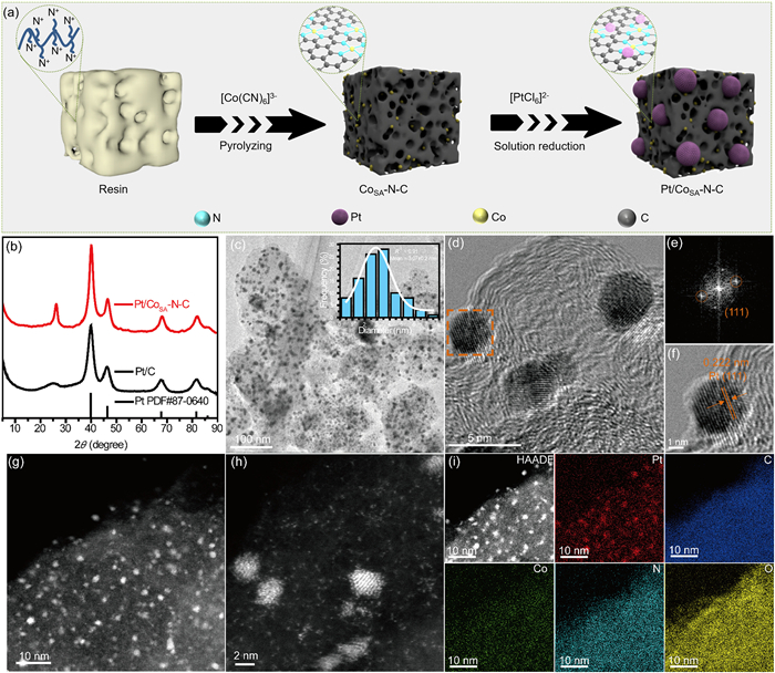
The detailed synthetic procedure of Pt/CoSA-N-C catalyst is shown in Fig. 1a. Firstly, the resin-derived single Co-Nx-rich carbon support (CoSA-N-C) was afforded by one-pot pyrolysis of the resin@[Co(CN)6]3− complex, of which the adsorption process was grounded on the complexation between N+ ion and [Co(CN)6]3− [41,42]. Subsequently, Pt precursor reduction led to the formation of NPs that adhered uniformly to the CoSA-N-C substrate derived from the resin (Pt/CoSA-N-C) via an in-situ self-assembled reduction strategy. The Pt/CoSA-N-C sample exhibited a specific surface area of 101.4 m2/g and an average pore diameter of 10.24 nm (Fig. S1 in Supporting information). The X-ray powder diffraction (XRD) pattern was applied to analyze the structural characteristics of Pt-based samples. As displayed in Fig. 1b, the Pt/CoSA-N-C sample exhibited a broad peak at approximately 26°, which is ascribed to the (111) crystal plane of carbon, indicating the successful formation of a highly graphitic carbon structure from the initial resin. Moreover, the Pt/CoSA-N-C catalyst displayed four diffraction peaks at 39.91°, 46.41°, 67.60°, and 81.56°, assigned to the face-centered cubic (fcc) Pt (111), (200), (220) and (311) planes (PDF#87-0640), respectively. This result illustrates the reduction of Pt precursor into metallic Pt.
Figure 1
Figure 1.
(a) Illustration of the synthetic procedure. (b) XRD patterns of Pt/CoSA-N-C and commercial Pt/C. (c) TEM images of Pt/CoSA-N-C (Inset: particle size distribution). (d) HRTEM images of Pt/CoSA-N-C catalyst. (e) FFT pattern and (f) enlarged HRTEM image of Pt/CoSA-N-C. (g-i) HAADF-STEM image and element mapping of Pt/CoSA-N-C sample.
The morphological aspects of Pt/CoSA-N-C catalyst were studied by transmission electron microscopy (TEM), high-resolution TEM (HRTEM), as well as high-angle annular dark-field scanning TEM (HAADF-STEM). As revealed in Fig. 1c, Pt NPs are evenly scattered on the carbon matrix with an average size of 3.07 nm and no obvious NPs agglomeration can be observed. Furthermore, the HRTEM image and the corresponding fast Fourier transform (FFT) image of Pt/CoSA-N-C presents a good crystallinity with the clear lattice fringe spacing of 0.222 nm, corresponding to the (111) planes of the fcc Pt, further confirming the successful reduction of the Pt NPs (Figs. 1d–f). Additionally, as displayed in Figs. 1g–i, the HAADF-STEM image combined with the relative element mapping reveals the uniform dispersion of Pt, Co, N, C and O elements, and Co is in the form of atomic dispersion around Pt NPs. The atomically dispersed Co-Nx site may tailor the electronic structure of Pt and change the adsorption of oxygen-obtaining intermediate [43].
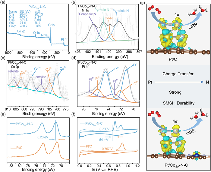
The valence state of surface elements and the composition of the Pt/CoSA-N-C catalyst were investigated through X-ray photoelectron spectroscopy (XPS) characterization. The survey spectra (Fig. 2a) verified the presence of Pt, O, C, N and Co signals within the Pt/CoSA-N-C catalyst, consistent with the result of element mapping. The content of Pt, C, N, O, and Co were determined to be 0.80, 90.13, 2.13, 6.09, and 0.85 at%, respectively. The high-resolution C 1s spectrum (Fig. S2 in Supporting information) indicated the signal of C—N bond, implying the successful conversion of N+ ion-containing resin into a nitrogen-doping carbon matrix. As illustrated in Fig. 2b, the N 1s spectrum of Pt/CoSA-N-C exhibited four distinct types: pyridine N at 398.9 eV, Co-N at 399.8 eV, pyrrolic N at 400.4 eV, and graphitic N at 401.4 eV [44,45]. The Co 2p spectrum of Pt/CoSA-N-C sample (Fig. 2c) could be deconvoluted into three couple doublets, attributing binding energies to Co3+ at 780.2 and 795.4 eV, Co2+ at 784.2 and 801.5 eV, and satellite peaks at 789.5 and 806.1 eV, respectively. Notably, the peak at 784.2 and 801.5 eV is widely recognized to Co-Nx bond, underscoring the established coordination between Co and N in the carbon substrate [46-48]. The coordination in Pt/CoSA-N-C, validated through a combined analysis of the N 1s and Co 2p spectra, holds significance in optimizing the electronic structure and fostering uniform Pt nucleation. The Pt 4f spectrum (Fig. 2d) exhibited that Pt on the surface of Pt/CoSA-N-C catalyst primarily existed in a metallic state, indicating the generation of a stable form of Pt. In contrast to commercial Pt/C, the Pt 4f7/2 peaks within Pt/CoSA-N-C demonstrated a higher binding energy shift of 0.28 eV towards higher values (Fig. 2e). This shift originates from the electrons transferred from Pt atoms to N atoms, resulting in the decreased electron density of Pt and a corresponding downward shift of the d-band center [49]. To further certificate this conclusion, we compared the CO stripping plots of Pt/CoSA-N-C catalyst and commercial Pt/C (Fig. 2f). The double CO stripping peak may originate from Pt nanoparticles, platinum oxide, and cobalt oxide, which is in agreement with XPS result [50,51]. More importantly, the onset potential for CO oxidation on Pt/CoSA-N-C catalyst significantly shifted to the negative direction (54 mV) relative to commercial Pt/C catalyst. These above results illustrate the existence of strong metal-support interaction (SMSI) between Pt NPs and CoSA-N-C support. This interaction modulated the electron density around Pt, leading to the weakened adsorption energy of oxygen-containing species on Pt sites and enhanced migration impediments for Pt on CoSA-N-C, thereby accelerating the four-electron ORR process and improving the durability of Pt/CoSA-N-C catalyst (Fig. 2g).
Figure 2
Figure 2.
(a) Survey spectrum of Pt/CoSA-N-C. XPS spectra of (b) N 1s, (c) Co 2p and (d) Pt 4f for Pt/CoSA-N-C sample. (e) Pt 4f XPS spectra and (f) CO stripping voltammograms of Pt/CoSA-N-C and commercial Pt/C catalysts. (g) The schematic diagram of ORR on Pt/CoSA-N-C and Pt/C catalysts.
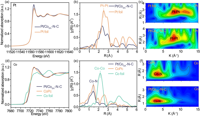
X-ray absorption spectroscopy (XAS) was conducted to further characterize the atomic coordination environment and electronic structures of the as-prepared samples. The X-ray absorption near-edge structure (XANES) of Pt in Pt/CoSA-N-C (Fig. 3a) suggested its oxidation states of Pt are slightly higher than zero as the higher white line intensity, but similar edge energy, and shapes of the XANES region relative to metallic Pt foil. This result is in agree with the XPS results, and further confirms the strong interaction between Pt-support. As shown in Fig. 3b, the corresponding extended X-ray absorption fine structure (EXAFS) spectra exhibited that the peaks positioned at ~2.3 Å represented Pt-Pt bonds. The least-squares EXAFS curve-fitting analyses (Fig. S3 and Table S1 in Supporting information) revealed that Pt NPs in Pt/CoSA-N-C were fitted by two Pt-Pt coordination paths with coordination numbers of 11.09 and 5.54, respectively. The k2-weighted Pt L3-edge WT EXAFS spectra for Pt foil exhibited a contour profile in k-space with a maximum strength of 8.0 Å−1 and 11.1 Å−1 (Fig. 3c). The contour intensity maximum for Pt/CoSA-N-C was blue-shifted slightly compared with that of Pt foil, which can be attributed to the electron transfer from Pt to CoSA-N-C support. In addition, the XANES spectrum of Co K-edge (Fig. 3d) was located at the left side and near cobalt phthalocyanine (CoPc), illustrating a higher oxidation state than Co in CoPc. Meanwhile, the Co K-edge EXAFS spectra (Fig. 3e) displayed a significant peak at ~1.5 Å, attributed to the first Co-N coordination shell. No Co–Co bond at 2.2 Å is found, indicating that Co atoms were stabilized in the form of Co-Nx [52-54]. The k3-weighted Co K-edge WT EXAFS spectra for Pt/CoSA-N-C showed a contour profile in k-space similar to that of CoPc with the contour intensity maximum at 3.2 Å−1 (Fig. 3f), implying the single Co-Nx site in the support possessed a comparable Co coordination to CoPc (i.e., CoN4). This conclusion was confirmed by the least-squares EXAFS curve-fitting analyses (Fig. S4 and Table S2 in Supporting information), as the Co in Pt/CoSA-N-C was fitted by a Co-N coordination path with the coordination numbers of 4.14. These XAS results indicated that the Pt/CoSA-N-C is composed of Pt nanoparticles and Co-N4-C support with a strong interaction, which is beneficial to the catalytic performance of ORR catalysis.
Figure 3
Figure 3.
(a) XANES spectra, (b) FT k2-weighted EXAFS spectra and (c) wavelet transforms for the k2-weighted EXAFS signals of the Pt L3-edge. (d) XANES spectra, (e) FT k2-weighted EXAFS spectra and (f) wavelet transforms for the k2-weighted EXAFS signals of the Co K-edge for Pt/CoSA-N-C and the reference samples.
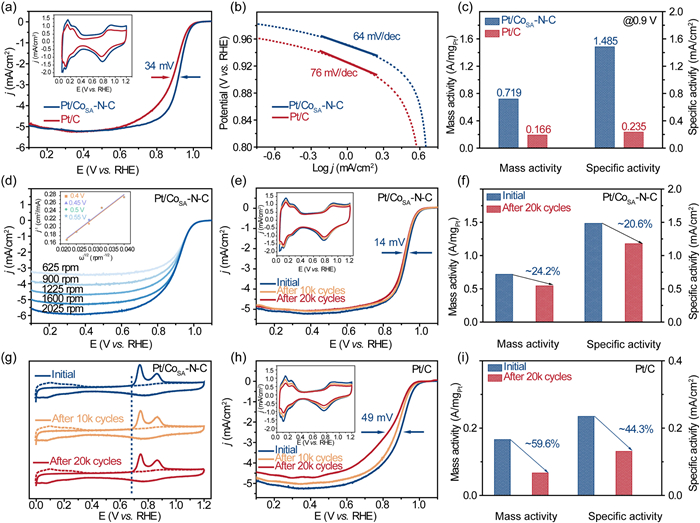
The electrocatalytic properties of the as-prepared Pt/CoSA-N-C catalyst were assessed using rotating disk electrode (RDE). Linear sweep voltammetry (LSV) profiles and the cyclic voltammetry (CV) curves collected in acid electrolytes are presented in Fig. 4a. The half-wave potential of commercial Pt/C (E1/2 = 0.889 mV) was 34 mV lower than Pt/CoSA-N-C sample (E1/2 = 0.923 mV), indicating the superior ORR activity of the engineered Pt/CoSA-N-C sample. This distinction was substantiated by the lower Tafel slope exhibited by Pt/CoSA-N-C catalyst (64 mV/dec) compared to commercial Pt/C (76 mV/dec), indicative of enhanced ORR kinetics (Fig. 4b). In order to further evaluate the catalytic activity, we normalized electrochemically active surface area (ECSA) and kinetic current density to obtain the mass activity (MA) and specific activity (SA), and the ECSA for the Pt/CoSA-N-C and commercial Pt/C catalyst is evaluated to be 48.41 and 70.52 m2/g, respectively (Table S3 in Supporting information). As manifested in Fig. 4c, the Pt/CoSA-N-C demonstrated markedly larger MA (0.719 A/mgPt) and SA (1.485 mA/cm2), approximately 4.3 and 6.3 times larger than those of commercial Pt/C (MA = 0.166 A/mgPt, SA = 0.235 mA/cm2), respectively. Such improvement was attributed to the synergistic effect between Pt NPs and the complementary Co-N4 sites. The electron transfer number (n) of the Pt/CoSA-N-C sample was deduced utilizing the Koutecky-Levich (K-L) equation, revealing a mean value approximating 4.0 (Fig. 4d), indicative of direct reduction of O2 to H2O. For exploring the effect of different reducing agents on the catalytic performance, three kinds of reducing agents were used to prepare the Pt/CoSA-N-C sample. The catalysts prepared using glucose and dimethylamino borane as reducing agents present low electrocatalytic activity compared with the catalyst prepared with sodium borohydride as reducing agent (Fig. S5 in Supporting information). Additionally, the ORR activity of Pt/CoSA-N-C is better than the majority of Pt-based catalysts reported recently (Table S4 in Supporting information).
Figure 4
Figure 4.
Comparison of (a) LSV curves (the inset is CV curves). (b) Tafel slopes. (c) MA and SA of commercial Pt/C and Pt/CoSA-N-C catalyst. (d) The rotation-rate-dependent current-potential curves (the inset is the Koutecky-Levich plots of Pt/CoSA-N-C for ORR). (e) The LSV curves (the inset is CV curves). (f) MA and SA, as well as (g) CO stripping voltammograms of Pt/CoSA-N-C sample after ADT. (h) The LSV curves (the inset is CV curves). (i) MA and SA of commercial Pt/C after ADT.
Stability is another crucial indicator to appraise the catalytic properties of electrocatalysts. As plotted in Fig. 4e, negligible deviation was observed for the CV curve (insert) and only a minor negative shift of 14 mV is noted in the E1/2 of Pt/CoSA-N-C after 20,000 cycles. Notably, the MA and SA of the Pt/CoSA-N-C catalyst merely decreased by 24.2% and 20.6%, respectively (Fig. 4f and Table S5 in Supporting information). Furthermore, according to the CO stripping voltammograms (Fig. 4g), the CO oxidation peak onset potential of Pt/CoSA-N-C showed no change before and after aging. Contrarily, commercial Pt/C lost 48 mV in E1/2 (Fig. 4h), accompanied by significant drops of 59.6% and 44.3% in MA and SA, respectively (Fig. 4i). Conclusively, we concluded that the Pt/CoSA-N-C possessed enhanced stability than commercial Pt/C, which is attribute to the SMSI between Pt and CoSA-N-C support. This assertion postulate was reinforced through TEM analysis. After accelerated durability testing (ADT), the morphology of Pt/CoSA-N-C remained basically unchanged, with no obvious nanoparticle agglomeration (3.59 nm) (Fig. S6 in Supporting information). In addition, the EDX image (Fig. S7 in Supporting information) confirmed uniform dispersion of Pt, Co, N, C and O elements, further verifying the improved durability of Pt/CoSA-N-C sample.
Density functional theory (DFT) calculations were conducted to investigate the underlying mechanism of the enhanced ORR properties for Pt/CoSA-N-C. Four computational models were constructed for comparison (Fig. S8 in Supporting information), including a six-atom Pt cluster supported on carbon layer (Pt/C), a CoN4 moiety supported on carbon layer (Co-N4-C), and a six-atom Pt cluster supported on Co-N4-C (Pt/Co-N4-C, Pt or Co site). The four-electron ORR pathway and crucial intermediates of Co-N4-C, Pt/Co-N4-C (Co site), Pt/Co-N4-C (Pt site) and Pt/C were presented in Figs. 5a–c and Fig. S9 (Supporting information), respectively. Additionally, the Gibbs free energy diagrams at different equilibrium potentials and corresponding calculated data were displayed in Fig. 5d, Figs. S10, S11 and Table S6 (Supporting information). The rate-determining step (RDS) for Pt/Co-N4-C (Pt sites), Pt/C, and Co-N4-C was viewed as the hydrogenation of the *OH to H2O, while for Pt/Co-N4-C (Co sites), the RDS was the conversion from O2 to *OOH. For Pt/Co-N4-C (Co sites) and Co-N4-C model, the theoretical overpotential is 0.25 V and 0.33 V, showing that the introduction of Pt can reduce the theoretical overpotential. Furthermore, the theoretical overpotential of Pt/Co-N4-C (Pt sites) (1.05 V) is lower than Pt/C (1.21 V) model, indicating that the synergistic effect of Pt and Co-N4 can enhance the catalytic activity for both Pt and Co site on Pt/Co-N4-C. Density of states (DOS) for Pt/Co-N4-C and Pt/C were further carried out to study the adjustment of electronic structure. As shown in Figs. 5e–g, Pt/Co-N4-C exhibited a greater abundance of electronic states near the Fermi-level than Pt/C, denoting better charge transfer ability. Furthermore, the d-band center of Pt/Co-N4-C and Pt/C, as well as the magnetization of Co-N4-C and Pt/Co-N4-C (Co site) revealed the electron transfer between the Pt and Co-N4 (Fig. 5h and inset) [55]. The d-band center for Pt/Co-N4-C (Pt site) (−2.72 eV) exhibited a displacement away from the Fermi level compared to Pt/C (−2.61 eV), illustrating easier dissociation of *OH species from Pt/Co-N4-C. To assess the interfacial stability, the binding energy (Eb) of Pt NPs with Co-N4-C and pure C supports were calculated. Remarkably, the Eb value for Pt/Co-N4-C stood at 3.19 eV, notably exceeding that of Pt/C (2.68 eV) (Fig. 5i). In addition, the charge density difference of Pt/Co-N4-C and Pt/C (inset in Fig. 5i) displays the redistribution of charge density at the interface, certifying the strong electron interaction between Pt and Co-N4-C, thereby hindering the detachment of Pt.
Figure 5
Figure 5.
The reaction scheme of ORR process on (a) Co-N4-C, (b) Co site and (c) Pt site of Pt/Co-N4-C models. (d) The Gibbs free energy diagrams at U = 1.23 V. The DOS on (e) Pt/Co-N4-C and (f) Pt/C models. (g) Comparison of DOS on Pt. (h) d-band center and (i) binding energy for Pt/Co-N4-C and Pt/C models. Inset in Fig. 5h exhibited the structure model, and inset in Fig. 5i is the charge density difference. The charge accumulation is colored in yellow, and depletion is colored in cyan.
In conclusion, we have successfully accomplished the fabrication of a Pt/CoSA-N-C catalyst, wherein Pt NPs are securely anchored onto a resin-derived single-atom CoSA-N-C carbon support, through the employment of an in-situ self-assembled reduction strategy. The numerous Co-N4 sites on the support serve as both adsorption sites and nucleation centers for Pt NPs, enhancing the interaction between active sites and the substrate, and optimizing the electronic structure of Pt. The resultant Pt/CoSA-N-C catalyst exhibited significantly improved ORR activity and stability outperforming the commercial Pt/C catalyst. Specifically, DFT calculations indicated that the synergistic effect of single Co-N4 sites and Pt NPs, coupled with the SMSI between Pt NPs and CoSA-N-C support not only weakens the adsorption of *OH intermediates, but also improves the migration barriers for Pt NPs on CoSA-N-C substrate, thus collectively enhancing the catalytic properties for ORR. This study holds the potential to spark further exploration into the realm of adeptly engineered carbon materials and high-performance catalysts tailored for ORR applications.
Declaration of competing interest
The authors declare that they have no known competing financial interests or personal relationships that could have appeared to influence the work reported in this paper.
Acknowledgments
This research work was financially supported by the Natural Science Foundation of China (Nos. 22169005, 22209186, 22068009 and 22262006), the Science and Technology Support Project of Guizhou Provincial Science and Technology Department (Nos. ZK[2023]050 and [2023]403), the Open Project of Institute of Dualcarbon and New Energy Technology Innovation and Development of Guizhou Province (No. DCRE-2023-06), Youth Innovation Promotion Association, CAS (No. 2023343), Self-deployed Projects of Ganjiang Innovation Academy, CAS (No. E355F006).
Supplementary materials
Supplementary material associated with this article can be found, in the online version, at doi:10.1016/j.cclet.2023.109354.
H. Luo, W.J. Jiang, S. Niu, et al., Small 16 (2020) 2001171. doi: 10.1002/smll.202001171
[55]
Z. Sun, L. Lin, J. He, et al., J. Am. Chem. Soc. 144 (2022) 8204–8213. doi: 10.1021/jacs.2c01153
Figure 1
(a) Illustration of the synthetic procedure. (b) XRD patterns of Pt/CoSA-N-C and commercial Pt/C. (c) TEM images of Pt/CoSA-N-C (Inset: particle size distribution). (d) HRTEM images of Pt/CoSA-N-C catalyst. (e) FFT pattern and (f) enlarged HRTEM image of Pt/CoSA-N-C. (g-i) HAADF-STEM image and element mapping of Pt/CoSA-N-C sample.
Figure 2
(a) Survey spectrum of Pt/CoSA-N-C. XPS spectra of (b) N 1s, (c) Co 2p and (d) Pt 4f for Pt/CoSA-N-C sample. (e) Pt 4f XPS spectra and (f) CO stripping voltammograms of Pt/CoSA-N-C and commercial Pt/C catalysts. (g) The schematic diagram of ORR on Pt/CoSA-N-C and Pt/C catalysts.
Figure 3
(a) XANES spectra, (b) FT k2-weighted EXAFS spectra and (c) wavelet transforms for the k2-weighted EXAFS signals of the Pt L3-edge. (d) XANES spectra, (e) FT k2-weighted EXAFS spectra and (f) wavelet transforms for the k2-weighted EXAFS signals of the Co K-edge for Pt/CoSA-N-C and the reference samples.
Figure 4
Comparison of (a) LSV curves (the inset is CV curves). (b) Tafel slopes. (c) MA and SA of commercial Pt/C and Pt/CoSA-N-C catalyst. (d) The rotation-rate-dependent current-potential curves (the inset is the Koutecky-Levich plots of Pt/CoSA-N-C for ORR). (e) The LSV curves (the inset is CV curves). (f) MA and SA, as well as (g) CO stripping voltammograms of Pt/CoSA-N-C sample after ADT. (h) The LSV curves (the inset is CV curves). (i) MA and SA of commercial Pt/C after ADT.
Figure 5
The reaction scheme of ORR process on (a) Co-N4-C, (b) Co site and (c) Pt site of Pt/Co-N4-C models. (d) The Gibbs free energy diagrams at U = 1.23 V. The DOS on (e) Pt/Co-N4-C and (f) Pt/C models. (g) Comparison of DOS on Pt. (h) d-band center and (i) binding energy for Pt/Co-N4-C and Pt/C models. Inset in Fig. 5h exhibited the structure model, and inset in Fig. 5i is the charge density difference. The charge accumulation is colored in yellow, and depletion is colored in cyan.

 DownLoad:


 下载:
下载:


