Citation:
Xinyu Ren, Hong Liu, Jingang Wang, Jiayuan Yu. Electrospinning-derived functional carbon-based materials for energy conversion and storage[J]. Chinese Chemical Letters,
2024, 35(6): 109282.
doi:
10.1016/j.cclet.2023.109282
Electrospinning-derived functional carbon-based materials for energy conversion and storage
English
Electrospinning-derived functional carbon-based materials for energy conversion and storage
Received Date:
31 July 2023 Accepted Date:
06 November 2023 Revised Date:
26 October 2023 Available Online:
15 June 2024
Abstract:
The over-exploitation of fossil fuel energy has brought about serious environmental problems. It would be of great significance to construct efficient energy conversion and storage system to maximize utilize renewable energy, which contributes to reducing environmental hazards. For the past few years, in terms of electrocatalysis and energy storage, carbon fiber materials show great advantages due to its outstanding electrical conductivity, good flexibility and mechanical property. As a simple and low-cost technique, electrospinning can be employed to prepare various nanofibers. It is noted that the functional fiber materials with different special structure and composition can be obtained for energy conversion and storage by combining electrospinning with other post-processing. In this paper, the structural design, controllable synthesis and multifunctional applications of electrospinning-derived functional carbon-based materials (EFCMs) is reviewed. Firstly, we briefly introduce the history, basic principle and typical equipment of electrospinning. Then we discuss the strategies for preparing EFCMs with different structures and composition in detail. In addition, we show recently the application of advanced EFCMs in energy conversion and storage, such as nitrogen species reduction reaction, CO2 reduction reaction, oxygen reduction reaction, water-splitting, supercapacitors and ion batteries. In the end, we propose some perspectives on the future development direction of EFCMs.
As the increasing demand for energy, the shortage of fossil energy and climate challenge have become global problems [1–5]. The dependence on fossil and related environmental problems can be effectively alleviated by developing renewable energy conversion and storage technologies [6–9]. In order to design an efficient energy conversion and storage system, it is the key to develop advanced and efficient electrode materials [10–14]. Although different reactions depend on different mechanisms, there are some common requirements for the physical and chemical property of electrode materials in both energy conversion and storage systems. These requirements include large specific surface area, high electrical/ionic conductivity, rich reaction sites, long-term structural stability, etc. [15–19].
One-dimensional carbon-based nanomaterials (CNMs) are ideal electrode materials because of their special uniform structure and fine scale, which make them have the characteristics of directional electron and ion transport [20,21]. Electrospinning is an effective method for preparing one-dimensional CNMs [22]. Electrospinning-derived functional carbon-based materials (EFCMs) are characterized by controllable structure and good stability, and present obvious advantages in energy conversion and storage [23–27]. There are several major advantages for EFCMs in energy conversion and storage: (1) Electrospinning technology can be easily combined with other methods to prepare functional materials [28–30]. (2) The EFCMs have large aspect ratio and specific surface area, which tend to promote the directional electron transport and enlarge the reaction interface [31,32]. (3) The EFCMs have good mechanical strength and flexibility, which provides a basis for the development of flexible devices [33–37]. (4) The EFCMs can be used as integrated electrodes without other adhesives [38–40], which can effectively avoid blocking of active sites.
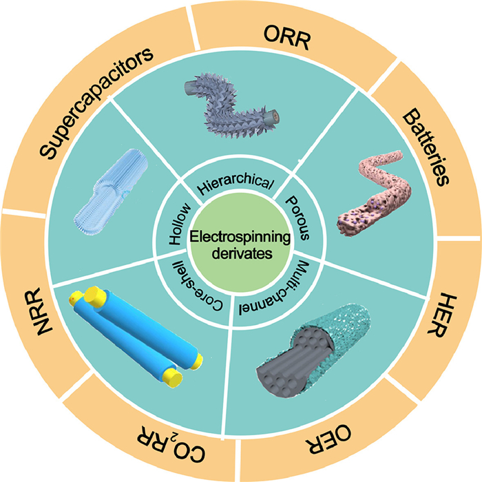
Based on the increasing application of EMCFs in energy conversion and storage [41–49], a summary was provided around these materials in this paper. Specifically, the important progress in structural design, controllable synthesis and multifunctional applications of EFCMs was reviewed (Fig. 1) [33,50–53]. This paper firstly referred the history, basic principle and equipment of electrospinning, and the synthetic method of EFCMs were summarized. Subsequently, the recent application of EFCMs in energy conversion and storage were expounded, including nitrogen reduction reaction (NRR), CO2 reduction reaction (CO2RR), oxygen reduction (ORR), hydrogen evolution reaction (HER), oxygen evolution reaction (OER), supercapacitors and ion batteries. Finally, the current state and future development of EFCMs were concluded.
Figure 1
Figure 1.
Electrospinning-derived functional carbon-based materials and its application. Reproduced with permission [33]. Copyright 2022, Wiley. Reproduced with permission [50]. Copyright 2023, Elsevier. Reproduced with permission [51]. Copyright 2021, Wiley. Reproduced with permission [52]. Copyright 2021, Elsevier. Reproduced with permission [53]. Copyright 2022, Elsevier.
Electrospinning can be traced back to the 16th century. Gilbert described the phenomenon that a droplet became cone under a strong electric field, which became the firstly documented account of the principle of electrospinning [54]. At the beginning of the twentieth century, patents involving methods and devices for dispersing fluids by electrostatic forces appeared [55]. The electrospinning apparatus was proposed by Formals and patented in 1934 [30]. Later Taylor named the cone shape of droplet arising from electric field Taylor cone according mathematical model, and this made great progress in the development of electrospinning theory [56]. The application of electrospinning mainly focused on filtration in early stage, but it did not attract wide attention of industry [57–60]. Until the 21st century, electrospinning has received more and more attention, and the mechanism of electrospinning has been constantly improved. The structural and component adjustability of electrospinning derivates make it possible to apply them in energy [61,62]. In addition, the emergence of electrospinning fibers with various structures, such as directional fibers and coaxial fibers, greatly enriched the applications of electrospinning fibers in the fields of energy [63–67], environment [68,69], and biomedicine [70–75].
2.2
The basic equipment and principle of electrospinning
Electrospinning device is mainly composed of high-voltage device, spinneret and receiving device. Under the action of electric field force and surface tension, the jet will be ejected and elongated, becoming longer and thinner. Meanwhile, the solvent will volatilize and solidify, and finally the disordered fiber membrane will be obtained on the receiving device.
The basic morphography of electrospinning nanofibers is influenced by electrospinning solution (polymer molecular weight, molecular chain structure, polymer solution viscosity), operating parameters (electric field force, propulsion rate, receiving distance, needle diameter), and environmental parameters (humidity, temperature, gas flow rate). And the concentration of polymer solution determines whether the fibers can form. In conclusion, the fiber diameter can be changed by adjusting the viscosity of the spinning solution and the parameters of the operating parameters, such as voltage, receiving distance, needle diameter, and pushing speed.
A variety of electrospinning polymer fibers can be used as carbon fiber precursors, such as polyacrylonitrile (PAN) and polyvinylidene fluoride (PVDF) [76]. The mechanical properties, fiber diameter, thermal stability and electrical conductivity of different polymer fibers are different. The spinning solution consisting polymer and proper solvent and other substances can be added during preparation. For example, adding carbon nanotubes to the spinning solution can improve the mechanical strength and electrical conductivity of the nanofibers [46]. Various metal salts and nanomaterials are usually added directly to the spinning solution as precursors of active components, and the active centers with different structures can be obtained by subsequent processes.
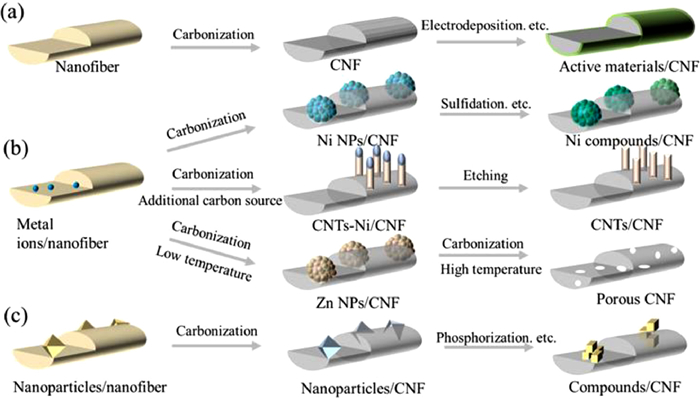
After calcination at high temperature, the electrospinning polymer nanofibers will lose weight and shrink, and finally turn into carbon nanofibers. Different carbon fiber precursors and different post-treatment operations can obtain different functional materials. The preparation of the electrospinning-derived functional carbon materials from different precursors is summarized in Fig. 2.
Figure 2
Figure 2.
Schematic diagram of the synthesis of electrospinning-derived functional fibers.
As shown in Fig. 2a, when the electrospinning solution is pure polymer solution, the nanofibers obtained after calcination are pure carbon fibers without any other substances. They can only be used directly in a few electrochemical reactions. This kind of carbon fiber is often used as a supporter to grow active materials on its surface by hydrothermal and electrodeposition methods, and then used as a functional material in the energy conversion and storage [77].
As shown in Fig. 2b, metal salts can be added to the polymer solution to obtain metal-containing fabric after electrospinning. A carbon fiber material containing metal active substances can be prepared after calcining. In addition, metal-active materials with different sizes and species can be obtained according to different amounts, metal salts and calcination conditions, such as single atoms, clusters, particles and alloys. Furthermore, the metallic compound can be obtained by treatment in a special atmosphere [41,42,49].
In addition to the active component, the metal added in the spinning solution can also be used as a pore-forming agent and a catalyst for the growth of secondary structural units. It has been widely reported that the membranes can be calcined to form porous carbon fibers by adding Zn species to the spinning solution, due to the volatilization of Zn at high temperature. Porous structure can enlarge reactive interface which poses great advantages in both electrocatalysis and energy storage [78–80]. Furthermore, it has been verified that metals in nanofibers can act as initiators of secondary structures, for example, fibers containing the metal Ni and Co can be calcined in atmosphere with carbon source, and Ni, Co can promote the growth of carbon nanotubes on the fiber surface. In short, nanowires, nanoparticles, nanorods and other secondary structures can be constructed on electrospinning fibers containing metal species by means of annealing, hydrothermal treatment, etc., to prepare hierarchical composite materials [81–85].
At present, many electrocatalysts or electrode materials are powder, which need to combine conductive agent and binder during application (Fig. 2c). It is tedious and additives easily block the active substances. Electrospinning shows great universality and can be employed in polymer solutions containing nanomaterials. Electrospinning fiber films can be directly used as independent electrodes after calcination, and flexible electronic devices [43,86,87]. More importantly, electrospinning easily endows the nano-materials with the fiber structure, making them have the characteristics of large specific surface, flexibility and so on, which are critical for electrode material.
2.4
Suitability of electrospinning-derived functional carbon fibers for energy conversion and storage
An increasing number of electrospinning functional materials have been used in the energy field, which can be mainly attributed to the following advantages of electrospinning functional materials:
2.4.1
Easy preparation
The corresponding polymer fibers can be obtained by electrospinning the polymer solution, and different fiber complexes can be prepared according to the different additives in spinning solution. In addition, through the combination of vapor deposition, hydrothermal and other methods, different target materials can be obtained according to the demand [88,89]. The preparation process of electrospinning derivative materials is not only simple and low cost, but also with the development of electrospinning technology, it is possible to realize large-scale production.
2.4.2
Diverse morphologies
Electrospinning fibers are characterized by a large aspect ratio, which facilitates the directional transport of electrons and ions, and the larger surface area can offer more active sites. Additionally, it is easy to construct some special structure such as porous structure [90–92], hollow structure [93–96] and core-shell structure [97–99]. For instance, Han et al. [44] designed N-doped porous CNFs supporting Pt single-atom catalysts utilizing the volatilization of Zn, which exhibited excellent hydrogen evolution performance. The rich pores structure in the fiber greatly increases the specific surface area (481.42 m2/g) and enlarge the reaction interface.
2.4.3
Flexibility and integration
With the increasing demand of portable devices, fabricating flexible electrode materials has attracted extensive attention. It has reported that the EFCMs exhibit outstanding flexibility and can be as flexible electrode materials [100–102]. Li et al. [103] fabricated flexible electrode (SnSbS/T-M@CNF) by electrospinning, it exhibited great application potential in the flexible battery. And a full cell consists of the electrode and polymer gel electrolyte, which has very low resistance and can power a 3 V LED lamp.
Moreover, electrospinning derivatives can be used as self-supporting electrodes, avoiding the use of binders and reducing catalyst shedding problems.
3.
Application of electrospinning-derived materials in energy conversion
Electrospinning cannot only prepare polymer fibers, but also synthesize functional materials with other simple technologies to control the structure and morphology of fibers [104–108]. Thus, unique structures or components can be designed and applied to specific electrocatalytic reactions. And the work involved in the part about electrospinning-derived function carbon materials for energy conversion is summarized in Table 1 [109–123].
Table 1
Table 1.
The applications of electrospinning-derived materials in the field of energy conversion.
As an important raw material of chemical products, ammonia is closely relevant with human life and industrial production [124,125]. NRR is an environmentally friendly ammonia synthesis technology, and hence it has received increasing attention [126–129]. However, on account of the high N≡N bond energy, the insolubility of nitrogen in water, so it is still a challenge to find suitable catalyst to efficiently convert the nitrogen to ammonia under ambient conditions.
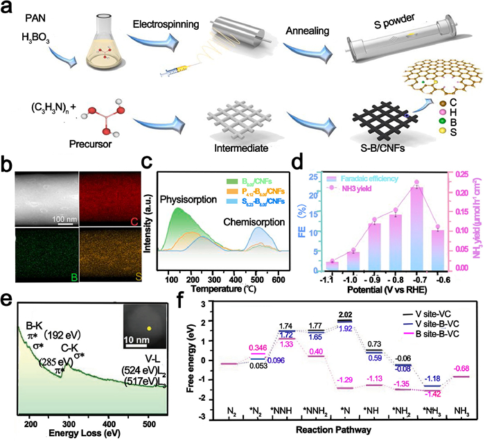
The introduction of heteroatoms facilitates the redistribution of electrons to enhance activity of catalysts. It is common to optimize catalysts by bringing in non-metal element (S, B, P) because these can offer electron to metal. Wen et al. [109] prepared the precursor of B-PAN by simple electrospinning method, and then introduced S element through calcination to obtain S, B co-doped fiber for NRR (Fig. 3a). As shown in Fig. 3b, the C, B and S evenly dispersed on the CNF. The temperature-programmed desorption (TPD) test of N2 (Fig. 3c) proves that the co-doping of S and B enhanced the chemical adsorption of N2, which was beneficial to accelerate the reaction. The S6.23-B8.09/CNFs showed efficient activity for NRR, and the FE reached 22.4% with NH3 yield of 0.223 µmol h−1 cm−2 (Fig. 3d). Similarly, Wen et al. [110] prepared precursor nanofiber membrane containing B and V by electrospinning, and then annealed at 1000 ℃ to synthesize carbon nanofibers including B and VC nanocrystals (B-VC/CNFs) to prove the selectivity of NRR. Electron energy loss (EELS) spectrum (Fig. 3e) proved that B atom successfully combined with VC crystal to form B-C-V structure. In addition, the TPD diagram indicated that B-C-V greatly improved the chemisorption ability of catalysts for N2, resulting in the enhancement of NRR performance. B-VC/CNFs achieved excellent FE of 46% with NH3 yield of 0.443 µmol h–1 cm–2 at −0.6 V vs. RHE. Density functional theory (DFT, Fig. 3f) showed that the electrons tended to transfer from B atoms to C atoms and changed the electronic structure of V and B. And B-C-V easily adsorb N2 and form NNH* due lower energy barrier.
Figure 3
Figure 3.
(a) Synthesis strategy of preparation of S-B/CNFs. (b) HAADF-STEM and STEM-EDX mapping images of S6.23-B8.09/CNFs. (c) N2 TPD curves of different catalysts. Reproduced with permission [109]. Copyright 2021, Elsevier. (d) The FE and NH3 yield of S6.23-B8.09/CNFs. (e) STEM-EELS spectrum of B-VC/CNF. Inset is the according B-VC. (f) Free energy of intermediates on various sites for NRR. Reproduced with permission [110]. Copyright 2021, Wiley.
Massive emissions of CO2 have caused global warming, ocean acidification, and carbon cycle imbalance, which pose serious treats to the living environment of animals, plants and human. It is a sustainable and attracting way to convert CO2 by electricity. The performance of CO2RR mainly depends on the adsorption and activation ability of the catalyst due to the insolubility and strong stability of CO2 [130,131].
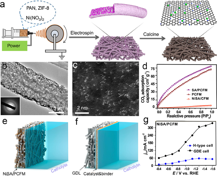
CO2RR takes place at gas-solid-liquid interface, and low diffusion of CO2 on catalyst surface influences the reaction process. In addition, the number of active sites is also a key factor to achieve high catalytic activity. Fortunately, these challenges can be overcome simultaneously by single-atom dispersed porous materials. The porous structure can increase the mass transfer rate, and the single-atom exhibit great atom utilization, which can promote the reaction rate and efficiency of CO2RR. Yang et al. [111] constructed a self-supporting porous carbon nanofibers containing single-atom nickel (NiSA/PCFM) electrocatalyst for CO2RR (Fig. 4a). It can see that the NiSA highly dispersed on porous carbon fibers (Figs. 4b and c). The exceptional structure of the coexistence of macropores and micropores accelerated the diffusion and adsorption of CO2 (Fig. 4d) and promoted the enrichment of CO2 around the active site. NiSA/PCFM showed high efficiency of CO2RR, partial current density of CO up to 308.4 mA/cm2 with the FECO of 88%. DFT proved that the Ni-N4—C site of NiSA/PCFM is easier to adsorb COOH* and promote the reaction. More importantly, NiSA/PCFM exhibited industrial current as an integral gas-diffusion electrode (Figs. 4e-g) and excellent durability. And NiSA/PCFM alleviated the problem of weak binding between the traditional powder catalyst and the substrate, ensuring the long-term activity of the catalyst. Products of CO2RR are numerous, and single ideal product can be obtained by adjusting the types of active sites. Yang et al. [112] prepared Cu atomically decorated through-hole CNFs (CuSAs/TCNFs) for CO2RR through electrospinning and annealing. The selectivity of the catalytic materials for CO2RR was changed because of different kinds of metal. CuSAs/TCNFs electrode achieved an excellent Faraday efficiency (FE) of 44% for methanol. DFT indicating that CO* was not easy desorb from Cu-N4 site due to positive free energy (0.12 eV), then CO* tended to transform into COH* with a favorable free energy barrier, and converted into methanol ultimately.
Figure 4
Figure 4.
(a) Diagram of Synthetic process of NiSA/PCFM. (b) HR-TEM image of NiSA/PCFM, the inset is lattice fringe. (c) HAADF-STEM image of NiSA/PCFM. (d) The comparsion of CO2 adsorption capacity of various catalysts. (e) NiSA/PCFM directly as GDE. (f) Common GDE with binder. (g) Partial current densities of NiSA/PCFM in H-type cell and GDE cell. Reproduced with permission [111]. Copyright 2020, Springer Nature.
In addition, CO2RR will be affected by changing the metal coordination environment to promote the selectivity of products. Compared with monometallic catalysts, alloy catalysts are composed of different metals and can provide different and interactive active sites. Different metal surface potentials and d-band centers interact each other, which effects the adsorption between active centers and intermediates. Hao et al. [113] obtained atomically dispersed Cu, Ni bi-atomic alloy catalysts (CuNi-DSA/CNFs) by electrospinning carbon fibers by electrospinning and chemical vapor deposition. Aberration-corrected high-angle annular dark-field scanning transmission electron microscope (AC-HAADF-STEM) can clearly show the bright spots of Cu and Ni metals. DFT showed that there was an obvious electronic interaction between Cu and Ni, and the CuN4—NiN4 site favored *COOH formation and promoted CO formation. CuNi-DSA/CNFs exhibited a high CO Faraday efficiency of 99.6% across a wide potential range.
3.3
Oxygen reduction reaction (ORR)
As a half reaction of fuel cells, it would be of great significance to improve the efficiency of ORR. It is well known that platinum-based catalysts can effectively improve the intrinsic slow kinetics of ORR. However, a cheap replacement is needed because of the high cost and scarcity of Pt [132,133].
Transition metal monatomic catalyst have attracted extensive concerns due to their maximum atomic utilization and low cost. In order to improve the performance of ORR, it is a good method to construct bi-atomic catalyst adjusting the electronic structure. Jiang et al. [114] designed Fe/Co dual monatomic catalysts by pyrolyzing electrospinning nanofibers (Fe, Co SAs-PNCF). Hierarchically porous structure accelerated ion diffusion and electron transfer. The onset potential and half-wave potential of Fe, Co SAs-PNCF was 1.04 V and 0.93 V respectively. As active center, the Fe and Co of N3-Fe-Co-N3 favored to adsorb oxygen molecules and accelerated the break of O—O bond to produce FeOOH/CoOOH intermediates.
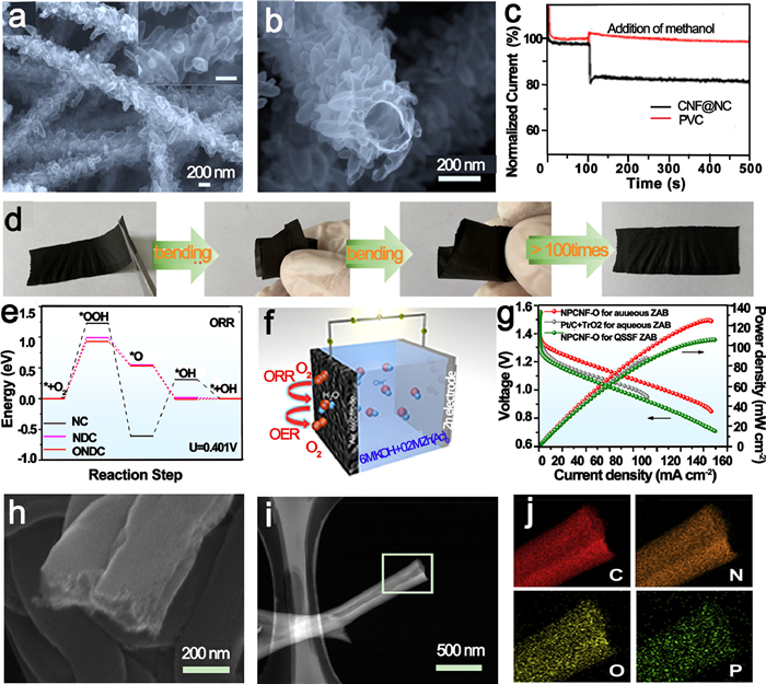
Nevertheless, there are still some problems for metal-based catalysts still have problems, such as easy corrosion, resulting in short service life of catalyst. Carbon-based metal-free catalysts generally show excellent acid and alkali resistance, causing widespread concern. Miao et al. [115] prepared CNFs with N-doped carbon particles (CNF@NC) (Figs. 5a and b) for ORR in alkaline media by in-situ growth of nanoparticles on electrospinning fibers. Grape-like carbon nanoparticles uniformly dispersed on carbon fiber, which is conducive to increase the reaction interface, and the nanofiber accelerated the mass transfer rates. The CNF@NC catalyst exhibited excellent methanol tolerance (Fig. 5c) indicating it is potential to apply in methanol alkaline fuel cells directly. And the half-wave potential reached 0.72 V at 7.7 mA/cm2.
Figure 5
Figure 5.
(a, b) SEM images of CNF@NC. (c) Chronoamperometric responses of various electrode in acidic media. Reproduced with permission [115]. Copyright 2018, Elsevier. (d) Pictures of NPCNF-O under bending. (e) Energy barriers of ORR step on different sites. (f) Aqueous zinc-air battery. (g) Discharge polarization profiles and relevant power density of ZABs. Reproduced with permission [116]. Copyright 2022, American Chemical Society. (h) SEM image of N, P–HCNF. (i) HAADF-STEM images of N, P-HCNF. (j) EDS mapping images. Reproduced with permission [117]. Copyright 2019, Elsevier.
In addition, the doping/co-doping of N, O, P can accelerate the electronic redistribution of active sites and improve the catalytic performance. Qiang et al. [116] constructed nitrogen-doped porous carbon nanofibers containing oxygen species (NPCNFs-O) as ORR electrocatalysts in alkaline media through simple electrospinning and calcination. The NPCNF-O possessed good flexibility (Fig. 5d) and C, N, O uniformly distributed in the nanofibers. NPCNF-O exhibited low onset potential of 0.98 V and half-wave potential of 0.85 V. Free energy diagrams (Fig. 5e) proved that the introduction of O optimized the adsorption energy of NPCNF, adjusted the local charge density. The zinc-air batteries assembled with NPCFF-O achieved a high power density of 125.1 mW/cm2 (Figs. 5f and g). Similarly, Gao et al. [117] prepared N, P co-doped hollow carbon nanofiber (N, P-HCNF) films (Figs. 5h and i) as a trifunctional catalyst for ORR, HER and OER using coaxial electrospinning technology. N, P-HCNF carried rich porous structure and layered graphite structure, and N, P co-doping regulated electronic structure. According to element mapping images, the C, N, O, and P elements evenly distributed on fiber (Fig. 5j). The N, P-HCNF performed equivalently to Pt/C with onset potential of 0.93 V and half-wave potential of 0.82 V.
3.4
Hydrogen reduction reaction (HER)
As a zero-carbon energy, hydrogen presents a high calorific value and utilization efficiency. HER is considered as one of the effective strategies to produce hydrogen energy. Platinum-based catalysts exhibit a good catalytic performance for HER. In order to reduce the production cost, it is indispensable to develop other platinum-free electrocatalysts for HER [134,135].
Single atom catalyst exhibits excellent catalytic efficiency for HER due to unique coordination environment. Furthermore, SAs were able to greatly improving the metal utilization rate while reducing the loading, and had attracted wide attention in the field of HER. Zhang et al. [118] designed Ru single atoms dispersed on N-doped CNFs (Ru SAs/NCNFs) through electrospinning and calcination under NH3. RuSAs densely and evenly scattered on carbon fiber. X-ray absorption fine structure (XAFS) spectrum further proved that Ru SAs and N-doped carbon formed synergistic effect, and NH3 can promote the generation of RuSAs. The Ru SAs/NCNFs showed superior HER activity, reached low overpotential of 34 mV at 20 mA/cm2. Another example about sing-atomic catalyst, Li et al. [119] designed Mo single atom dispersed on nitrogen-doped multi-channel carbon nanofibers (Mo@NMCNFs) to improve HER activity (Fig. 6a). Mo@NMCNFs exhibited obvious pore and multi-channel structure, and Mo single atom uniformly distributed on the fiber surface with high density (Figs. 6b and c). Mo@NMCNFs shows excellent HER performance (Fig. 6d) in acidic media with an overpotential of 66 mV and Tafel slope of 48.9 mV/dec at 10 mA/cm2. DFT further explored the mechanism of Mo single atom improving HER activity. Mo coordinates with C and N, and the electronic structure changed which decreased the free energy of H adsorption and made it easier to release hydrogen.
Figure 6
Figure 6.
(a) Diagram of preparation of Mo@NMCNFs. (b) SEM images. (c) AC-HAADF-STEM images of Mo@NMCNFs. (d) Overpotentials of various catalysts. Reproduced with permission [119]. Copyright 2021, America Chemical Society.
Oxygen evolution reaction (OER) involves multi-electron transfer, and it is effective to boost reaction dynamic to enhance reaction efficiency by developing productive catalysts. Hence, it is attractive to develop low-cost, high-efficiency and stable electrocatalysts for OER [136,137].
Transition metal catalysts for OER are increasingly being reported due to their low cost and the introduction of heteroatoms will adjust the electronic structure of metals to optimize the performance of catalysts. Lu et al. [120] designed porous CNFs encapsulating Co@N—C nanoparticles (Co@N—C/PCNF) as bifunctional oxygen electrocatalyst combing electrospinning technology and ultra-fast high-temperature shock technology. There were abundant pores in composite fibers with core-shell structure, and Co was highly dispersed throughout nanofibers (Figs. 7a-c). The Co@N—C/PCNF achieved low overpotential of 289 mV at 10 mA/cm2 for OER. The result of DFT showed that the free energy of Co-N-C site is lower, and it was easier to adsorb O*, OH* and other intermediates.
Figure 7
Figure 7.
(a) SEM and (b) higher magnification SEM images of Co@N—C/PCNF. (c) TEM image of nanoparticles and its size distribution in insert. Reproduced with permission [120]. Copyright 2021, Wiley. (d-j) Elemental mapping of FeCo@MNC. (k) TEM images of FeCo@MNC. (l) N2 sorption isotherms of various catalysts. (m) The comparison of LSV before and after 2000 CV cycles. Reproduced with permission [121]. Copyright 2019, Elsevier.
In addition to mono-metal catalysts, bimetallic catalysts for OER have also been reported. Li et al. [121] prepared carbon fiber with mesoporous encapsulating FeCo nanoparticles (FeCo@MNC) as bifunctional catalysts for OER and ORR. Elemental mapping of FeCo@MNC indicated C, N, Fe and Co were evenly dispersed (Figs. 7d-j). The nanofibers showed larger BET specific surface area and nanoparticles uniformly dispersed (Figs. 7k and l). The FeCo@MNC showed long stability (Fig. 7m) and low overpotential of 240 mV.
3.6
Water-splitting
Hydrogen evolution and oxygen evolution catalysts with high catalytic activity are needed for water decomposition, but few of them can produce hydrogen and oxygen at the same time. High entropy alloy (HEA) nanomaterials have multiple active sites, which can achieve selective adsorption for different intermediates to promote the conversion of water to H2 and O2 [138–140].
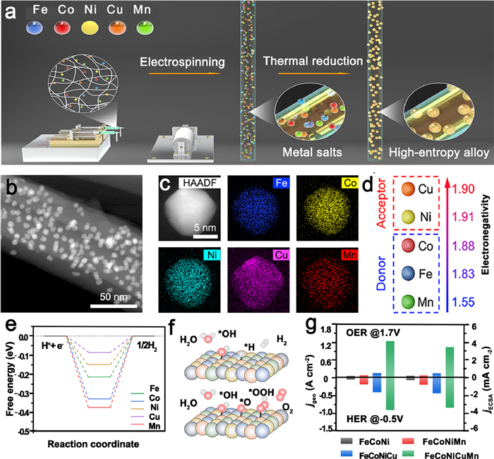
The ultra-high activity of high-entropy alloys mainly depends on the synergistic effect of various metals. The key to successful synthesis of high-entropy alloys is to control the metal components and promote the surface homogeneity of HEA. Multiple metal components easily form a homogeneous solution with the polymer, and each component dispersed nanofiber membrane precursors can be obtained directly by electrospinning. Electrospinning technology provides a new way for the preparation of HEA. Zhu et al. [122] prepared single face-centered cubic phase High-entropy alloy (FeCoNiCuMn HEA) through annealing electrospinning nanofibers to promote HER and OER (Fig. 8a). As shown in Figs. 8b and c, the alloy nanoparticles composed by multiple metal uniformly dispersed on three-dimensional carbon fiber skeleton. The FeCoNiCuMn HEA showed low overpotential of 281 mV at 100 mA/cm2 for HER, and the overpotential for OER was 386 mV at 200 mA/cm2 (Fig. 8g). The DFT (Figs. 8e and f) indicated the Mn, Co, Fe tended to denote electrons to Ni and Cu because of weak electronegativity (Fig. 8d), which changed electron distribution among HEA and decreased the intermediate adsorption energy of Cu sites, accelerating the electrocatalytic water splitting process. Similarly, Hao et al. [123] using the same way prepared the FeCoNiMnRu HEA for the conversion of H2O to O2 and H2. There were electrons transfer from Fe, Co, Ni and Mn to Ru, which increased the local electron density of Ru and improved the adsorption capacity of active sites. The FeCoNiMnRu/CNFs achieved low Tafel slope of 67.4 mV/dec while overpotential of 71 mV for HER, the lowest overpotential of 308 mV 100 mA/cm2 for OER.
Figure 8
Figure 8.
(a) Preparation of HEA/CNF. (b) HAADF-STEM images of FeCoNiCuMn HEA/CNFs. (c) STEM-EDX mapping images of NPs. (d) The difference of electronegativity among metals. (e) Free energy of water dissociation. (f) The reaction process on HEA particles. (g) Current density and ECSA of various catalysts for HER and OER. Reproduced with permission [122]. Copyright 2023, Royal Society of Chemistry.
4.
The application of electrospinning nanofiber in the energy storage
The development of portable electronic devices requires matching flexible power supplies. Electrospinning nanofibers have excellent flexibility and mechanical properties, and their application in the energy equipment has been reported. And the relevant work about electrospinning-derived function carbon materials for energy storage is summarized in Table 2 [141–146].
Table 2
Table 2.
The applications of Electrospinning-derived materials in energy storage.
Supercapacitors commonly exhibit high power density and the property of fast charging and discharging, which are important for industry society. The need of wearable electronic devices has promoted the research of flexible supercapacitors [100,147,148].
Carbon cloth and carbon nanotubes (CNTs) are widely used in flexible and binder-free electrodes for the direct growth of various electrochemical active materials, which exhibit good capacitive properties. Electrospinning nanofibers are also ideal materials to support active materials. Qiu et al. [141] obtained carbon nanotubes grown vertically on ECNFs (VACNT/CNFs) utilizing electrospinning and calcination. The vertically dispersed carbon nanotubes were initiated by nickel salt in the spinning solution. And the amount of metal would influence the structure and morphology CNTs. Vertically dispersed CNTs possess high conductivity, which enabled efficiently charge aggregation and transport. The supercapacitors consisting of VACNTs/CNFs achieved high energy density of 98.8 Wh/kg at 1.0 A/g in ionic liquid electrolytes electron. And the electronic double-layer (EDL) supercapacitors fully charged lamp (3.2 V), kept long-term durability.
The electrochemical substances of pseudocapacitors depose on the electrode surface or in the bulk phase which is different from EDL capacitor. Pseudocapacitors are generated throughout the electrode to obtain higher capacitance and energy density. The growth of secondary nanoarrays on electrospinning fibers is an effective method for improving the capacitance of electrodes due to their large specific surface area. Shi et al. [142] prepared Ni-CAT nanowires grown on carbon nanofibers (Ni-CAT NWAS/CNF) as independent electrode by treat electrospinning nanofibers containing Ni with facile one-step in situ hydrothermal (Fig. 9a). The vertical growth of nanowires (Figs. 9b-d) in fiber epitaxy effectively promoted electron transfer and diffusion. Ni-CAT NWAs/CNF electrode without conductive additives achieved a high capacitance of 40.5 mF/cm2. And Galvanostatic charge/discharge exhibited a low iR drop from 0.1 mA/cm2 to 2 mA/cm2.
Figure 9
Figure 9.
(a) Synthetic process of Ni-CAT NWAs/CNF. (b) SEM images. (c) STEM images. and Elemental mapping of Ni-CAT NWAs/CNF. (d) structural diagram of Ni-CAT. Reproduced with permission [142]. Copyright 2021, America Chemical Society. (e) Disposal process of nickel. (f) Synthesis process of NiGa2S4/Ni@CNF. (g) TEM image of NiGa2S4/Ni@CN. Reproduced with permission [143]. Copyright 2021, Elsevier.
Similarly, Kim et al. [143] grew NiGa2S4 nanosheets (Figs. 9e-g) on electrospinning PAN-based carbon nanofibers for high-power flexible supercapacitor electrodes. The intricate fiber structure was conducive to increasing the electrode-electrolyte interfacial activity and charge storage. The cyclic voltammetry (CV) curve had no distortion and remained overlapped while the electrodes were bent, which proved the excellent mechanical performance of NiGa2S4/Ni@CNF. The NiGa2S4/Ni@CNF capacitor achieved an outstanding capacitance of 488 F/g at 0.5 A/g. Additionally, the energy density reached 41 Wh/kg.
4.2
Batteries
Electrospinning is increasingly used in the field of batteries; and it provides a new method for the preparation of flexible electrodes.
Lithium-ion batteries (LIBs) gradually become market leaders in the field of power supply on account of its long cycle life and environmentally friendly. It is critical to develop flexible LIBs with excellent electrochemical performance to meet the needs of flexible electronic devices [22,149,150].
Flexible electrodes are one of the important components of flexible LIBs, and the development of flexible electrodes that can uniformly deposit lithium is very attractive. ECNFs with chemical stability and mechanical flexibility are considered as an important substrate for uniformly dispersing lithium flux, which are the prior substrate for preparing flexible electrode materials. Xia et al. [144] prepared porous Sb2S3/TiO2/C nanofiber films as flexible anodes for Li+ batteries by calcining electrospinning nanofibers membrane (Fig. 10a). Sb2S3/TiO2/C nanofibers with high specific area promoted Li+ transport. In addition, the porous structure of the fibers was conducive to slow down the volume fluctuations of alloying/dealloying. The prepared nanofiber membrane exhibited good flexibility and remained intact after fold treatments (Figs. 10b-d). The Li+ battery using Sb2S3/TiO2/C nanofibers as anode achieved excellent discharge capacity of 261.6 mAh/g. More importantly, the porous Sb2S3/TiO2/C nanofiber membranes exhibited the prospect of practical applications because a fully charged full Li+ battery can turn on 16 light emitting diodes.
Figure 10
Figure 10.
(a) Synthetic process of Sb2S3/TiO2/C. (b-d) Pictures of Sb2S3/TiO2/C under bending. Reproduced with permission [144]. Copyright 2021, Elsevier. (e) Synthetic of FeP@NPC membrane. (f) The TEM images of FeP@NPC. (g) The diagram of Na3V2(PO4)3//FeP@NPC. (h) The galvanostatic charge/discharge for various cycles. Reprodeced with permission [146], Copyright 2020, Elsevier.
In view of the high cost of lithium, it is necessary to develop low-cost ion batteries. Sodium ions are abundant in the crust of earth and sea water, which are expected to replace Li+ battery. Furthermore, Na+ more easily diffuse and transfer in the electrolyte due to its large volume, which has a broad application prospect. There are more and more researches about flexible Na+ battery [35]. The traditional metal or ceramic electrode materials may encounter shedding problems active material during working process. Electrospinning technology can prepare flexible self-supporting electrodes to effectively alleviate this problem. It has been proved that phosphorus doping can optimize the active sites and improve the efficiency of sodium ion batteries. Liu et al. [145] prepared flexible Sn2+/PAN/PMMA composite film by electrospinning, and then obtained porous carbon nanofibers wrapping Sn4P3 (Sn4P3 NPs@CNF) through calcination and low-temperature phosphating as negative electrode of Na+ battery. The Sn4P3 NPs@CNF film exhibited excellent flexibility, and the current-potential response kept continuous and stable under flat, bending and relaxation conditions. In the half-cell test, the average coulomb efficiency (CE) of Sn4P3 NPs@CNF reached 99.6%, which still maintained after several times of electroplating stripping. Sn4P3 NPs@CNF @Na׀׀NaVPO4F exhibited energy density of 261.8 Wh/kg in bending state. In the same way, Shi et al. [146] prepared three-dimensional interconnected N, P co-doped carbon fiber wrapping FeP nanoparticles (FeP@NPC) as the independent electrode of flexible Na+ battery by electrospinning technology and phosphating technology (Fig. 10e). The film showed good flexibility and mechanical property, and remained intact at different bending angles. The three-dimensional interconnected carbon skeleton derived from PAN (Fig. 10f) shortened the ion/electron transport path and promote the reaction kinetics. The FeP@NPC showed excellent long-term retention rate of 73% after 1000 cycles in the half-cell test. The initial charge/discharge specific capacity of the Na3V2(PO4)3//FeP@NPC (Fig. 10g) achieved 349 and 296 mAh/g (Fig. 10h), respectively.
5.
Conclusion and prospective
In this paper, the methods and advantages of electrospinning to design functional materials and the application of electrospinning-derived fibers in electrocatalytic reaction and battery are introduced. In short, electrospinning-based materials showed broad range of applications in energy conversion and storage. Nanofibers with special structure prepared by electrospinning combined with post-treatment such as calcination, can as an intermediate layer or electrode materials for ion batteries and electrochemical reactions and exhibit excellent electrochemical properties. Although electrospinning is an important technology to produce nanofibers, several challenges remain to be overcome before electrospinning materials used in energy-related applications on a large scale.
5.1
Mass production
From the perspective of industrial production and application, mass production is the main bottleneck in the application of electrospun nanofibers for energy storage and conversion. "Multi-nozzle" electrospinning machines have been developed to produce nanofibers on a large scale, but their further development was hindered by high cost.
5.2
Controllability of one-dimensional structures
The diameter of nanofibers, the distribution of doped particles, the size and distribution of pore size, electrical conductivity others aspects can exert a significant impact on electrochemical properties. Fine fibers can provide shorter electron diffusion paths and improve electrochemical properties, but uniform nanofibers with diameters less than 50 nm are difficult to achieve. It is very important to optimize these parameters to design more favorable structures to meet the requirements of high-performance energy devices.
5.3
Safety
The solvents dissolving polymer are usually toxic and corrosive, which pose a threat to human health and the environment. It is indispensable to develop nontoxic solution and environment-friendly electrospinning process.
5.4
Practical application
Flexible ECNFs can be used as electrodes, separators and electrolytes in flexible battery. It is hard how to successfully assemble these components into practical devices. In addition, the mechanical properties and flexibility of flexible nanofibers need to be further optimized and developed.
Although many challenges remain, electrospinning technology has been validated to produce nanofibers for energy conversion and storage.
Declaration of competing interest
The authors declare no conflict of interests.
Acknowledgments
This work was supported by the Natural Science Foundation of Shandong Province (No. ZR2022QE076) and the National Natural Science Foundation of China (No. 52202092).
[1]
J. Beagley, BMJ 381 (2023) 1271.
[2]
C. Hendrix, V. Koubi, J. Selby, A. Siddiqi, N. von Uexkull, Nat. Rev. Earth. Environ. 4 (2023) 144–148. doi: 10.1038/s43017-022-00382-w
[3]
S. Hu, X. Zhou, D. Yan, et al., Renew. Sust. Energy Rev. 181 (2023) 113316. doi: 10.1016/j.rser.2023.113316
[4]
G. Loffreda, R. Osborne, E. Arteaga-Cruz, F. Baum, BMJ 381 (2023) 843.
[5]
J. Rising, M. Tedesco, F. Piontek, D. Stainforth, Nature 610 (2022) 643–651. doi: 10.1038/s41586-022-05243-6
[6]
S. Pryor, R. Barthelmie, M. Bukovsky, L. Leung, K. Sakaguchi, Nat. Rev. Earth Environ. 1 (2020) 627–643. doi: 10.1038/s43017-020-0101-7
[7]
M. Zastempowski, Renew. Sust. Energy Rev. 178 (2023) 113263.
Figure 3
(a) Synthesis strategy of preparation of S-B/CNFs. (b) HAADF-STEM and STEM-EDX mapping images of S6.23-B8.09/CNFs. (c) N2 TPD curves of different catalysts. Reproduced with permission [109]. Copyright 2021, Elsevier. (d) The FE and NH3 yield of S6.23-B8.09/CNFs. (e) STEM-EELS spectrum of B-VC/CNF. Inset is the according B-VC. (f) Free energy of intermediates on various sites for NRR. Reproduced with permission [110]. Copyright 2021, Wiley.
Figure 4
(a) Diagram of Synthetic process of NiSA/PCFM. (b) HR-TEM image of NiSA/PCFM, the inset is lattice fringe. (c) HAADF-STEM image of NiSA/PCFM. (d) The comparsion of CO2 adsorption capacity of various catalysts. (e) NiSA/PCFM directly as GDE. (f) Common GDE with binder. (g) Partial current densities of NiSA/PCFM in H-type cell and GDE cell. Reproduced with permission [111]. Copyright 2020, Springer Nature.
Figure 5
(a, b) SEM images of CNF@NC. (c) Chronoamperometric responses of various electrode in acidic media. Reproduced with permission [115]. Copyright 2018, Elsevier. (d) Pictures of NPCNF-O under bending. (e) Energy barriers of ORR step on different sites. (f) Aqueous zinc-air battery. (g) Discharge polarization profiles and relevant power density of ZABs. Reproduced with permission [116]. Copyright 2022, American Chemical Society. (h) SEM image of N, P–HCNF. (i) HAADF-STEM images of N, P-HCNF. (j) EDS mapping images. Reproduced with permission [117]. Copyright 2019, Elsevier.
Figure 6
(a) Diagram of preparation of Mo@NMCNFs. (b) SEM images. (c) AC-HAADF-STEM images of Mo@NMCNFs. (d) Overpotentials of various catalysts. Reproduced with permission [119]. Copyright 2021, America Chemical Society.
Figure 7
(a) SEM and (b) higher magnification SEM images of Co@N—C/PCNF. (c) TEM image of nanoparticles and its size distribution in insert. Reproduced with permission [120]. Copyright 2021, Wiley. (d-j) Elemental mapping of FeCo@MNC. (k) TEM images of FeCo@MNC. (l) N2 sorption isotherms of various catalysts. (m) The comparison of LSV before and after 2000 CV cycles. Reproduced with permission [121]. Copyright 2019, Elsevier.
Figure 8
(a) Preparation of HEA/CNF. (b) HAADF-STEM images of FeCoNiCuMn HEA/CNFs. (c) STEM-EDX mapping images of NPs. (d) The difference of electronegativity among metals. (e) Free energy of water dissociation. (f) The reaction process on HEA particles. (g) Current density and ECSA of various catalysts for HER and OER. Reproduced with permission [122]. Copyright 2023, Royal Society of Chemistry.
Figure 9
(a) Synthetic process of Ni-CAT NWAs/CNF. (b) SEM images. (c) STEM images. and Elemental mapping of Ni-CAT NWAs/CNF. (d) structural diagram of Ni-CAT. Reproduced with permission [142]. Copyright 2021, America Chemical Society. (e) Disposal process of nickel. (f) Synthesis process of NiGa2S4/Ni@CNF. (g) TEM image of NiGa2S4/Ni@CN. Reproduced with permission [143]. Copyright 2021, Elsevier.
Figure 10
(a) Synthetic process of Sb2S3/TiO2/C. (b-d) Pictures of Sb2S3/TiO2/C under bending. Reproduced with permission [144]. Copyright 2021, Elsevier. (e) Synthetic of FeP@NPC membrane. (f) The TEM images of FeP@NPC. (g) The diagram of Na3V2(PO4)3//FeP@NPC. (h) The galvanostatic charge/discharge for various cycles. Reprodeced with permission [146], Copyright 2020, Elsevier.

 DownLoad:


 下载:
下载:


