Advanced Catalysis and Green Manufacturing Collaborative Innovation Center, CNPC-CZU Innovation Alliance, School of Petrochemical Engineering, Changzhou University, Changzhou 213164, China
b.
Institute of Functional Nano & Soft Materials (FUNSOM), Jiangsu Key Laboratory for Carbon-Based Functional Materials & Devices, Soochow University, Suzhou 215123, China
c.
Zhejiang Key Laboratory of Petrochemical Environmental Pollution Control, National Engineering Research Center for Marine Aquaculture, Marine Science and Technology College, Zhejiang Ocean University, Zhoushan 316004, China
Received Date:
19 June 2023 Accepted Date:
07 September 2023 Revised Date:
01 September 2023 Available Online:
15 April 2024
Abstract:
Photocatalytic conversion of CO2 into small-molecule chemical feedstocks can meet the growing demand for energy and alleviate the global warming. Herein, a p-n ZnO@CDs@Co3O4 heterojunction with sandwich structure was constructed by calcination method of self-assembled ZIF-8@CDs@ZIF-67. The ZnO@CDs@Co3O4 with well-defined interfacial structure exhibited the significantly enhanced photocatalytic CO2 reduction activity, and the optimal catalyst indicated the (CO + CH4) evolution rate of 214.53 µmol g−1 h−1 under simulated solar light, which was superior to ZnO, Co3O4 and binary ZnO@Co3O4. The internal cavity, exposed active sites, multiple interfaces and constructed p-n heterojunction can facilitate the light harvesting and photoexcited electron transfer. Besides, after introduction of CDs placed in the middle layer between ZnO and Co3O4, CDs with excellent photoelectric property further promoted charge separation and migration. This work represents an appealing strategy to construct well-defined photocatalysts for boosting CO2 photoreduction.
The conversion of CO2 into valuable chemical fuels including CO, CH4, and CH3OH through solar energy can be considered as an attractive way [1–5]. Owing to the high thermodynamic stability of the linear CO2 molecule involved, the photocatalytic CO2 reduction reaction suffers from poor performance and low energy conversion efficiency [6]. Photosensitizer and/or cocatalyst loading [7], morphology regulation [8], doping [9], and heterojunction construction are efficient approaches to improve photocatalytic CO2 reduction performance [10]. Recently, many photocatalysts including metal oxides (ZnO and Co3O4) [11], metal phosphides (NiP and CoP) [12], metal-organic frameworks (ZIF-67 and ZIF-8) [13,14], and so on [15], have been reported as favorable catalysts to improve CO2 photoreduction [16–20].
Metal organic frameworks (MOFs) constructed by periodically arranged metal atoms as well as organic ligands act as ideal templates to synthesize functional materials with unique structural characteristics [21]. Especially, porous sandwich, core-shell, yolk-shell heterostructures derived from MOF-on-MOF precursors not only afford the close interface contact, but expose abundant surface reaction sites because of shell permeability and internal voids [22]. For instance, ZIF-8@ZIF-67 derived n-ZnO@p-Co3O4 heterostructure with appropriate position of energy band and sufficient contact areas indicate the excellent photocatalytic performance [23]. However, owing to ZnO with the weak property of absorbing visible-light, and low electron transport efficiency in the heterostructure, the ZnO@Co3O4 still exhibits a low photocatalytic CO2 reduction performance [24].
Much effort has been devoted to pursuing photocatalysts with high performance, among which the combination of cocatalyst and MOFs-derived catalyst has received great attention [25]. Recently, carbon dots (CDs) with a size below 10 nm, low toxicity and good electron transfer capability have been widely studied as an appropriate choice to form heterojunction with MOFs-derived catalyst [26]. CDs possess the broad solar absorption attributed to the strong π-conjugated structure, and it is noted that CDs as electron acceptor/reservoir can remarkably reduce the electron-hole recombination in photocatalysts [27]. Consider that ZnO@Co3O4 is short of strong light absorption and subjected to high charge recombination, the combination of CDs and ZnO@Co3O4 acts as an efficient approach to promote their photocatalytic activity predictably.
Inspired by these considerations, we designed a novel sandwich ZnO@CDs@Co3O4 (ZCC) by a one-step calcination of ZIF-8@CDs@ZIF-67 (ZCZ), and the photocatalytic CO2 reduction reaction (CO2RR) of ternary heterostructure was investigated. Characterizations reveal the phase and micro-structure, electrochemical properties, energy band structure, electron transfer pathway and photocatalytic mechanism of CO2 over obtained photocatalysts. The formed p-n heterojunction can accelerate the charge transfer and CDs in the middle layer can provide the effective electron transport, which is conducive to the enhancement of CO2RR activity.
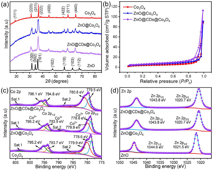
Fig. S1 (Supporting information) display the XRD patterns of ZIFs, ZIFs derivatives, and ternary composites. The diffraction patterns of ZIF-8@ZIF-67 are consistent with the XRD pattern of ZIF-8 and ZIF-67, suggesting that the dual MOFs have been successfully synthesized (Fig. S1) [28]. From Fig. 1a, the ZnO@Co3O4 (ZC) displays the diffraction peaks of both ZnO and Co3O4, indicating that the Co3O4 is coated on the ZnO after one-step calcination. After loading of CDs, the ternary heterostructure exhibits the same diffraction peaks as for ZnO@Co3O4, which can be assigned to the low CD loading amount, suggesting that the characteristic diffraction peaks of ZnO@Co3O4 are maintained. N2 adsorption-desorption isotherms as well as the corresponding porous characteristics of ZIF-8@ZIF-67 and the ternary composites are depicted in Fig. S6 (Supporting information) and Fig. 1b, respectively. Notably, the ZIF-8@ZIF-67 (Table S1 in Supporting information) exhibits the high specific surface area of 1282.63 m2/g, which reveals that the porous structure remains intact after in-situ synthesis. Besides, the ZnO@CDs@Co3O4 belongs to the type-Ⅳ isotherm, indicating that the high specific surface area is 21.70 m2/g, while ZnO@Co3O4 and Co3O4 show a low surface area (ZnO@Co3O4: 18.77 m2/g; Co3O4: 13.08 m2/g). The ZIF derivatives and ternary composite after pyrolysis are all characteristic of mesoporous material, suggesting that heterostructure can produce the active sites and afford the charge transport channels. The XPS spectra of Co 2p in Co3O4 (Fig. 1c) exhibit that four major peaks at 778.6, 779.9, 793.7, and 795.2 eV are agreement with Co3+ 2p3/2, Co2+ 2p3/2, Co3+ 2p1/2 and Co2+ 2p1/2, respectively. In addition, there are two satellite peaks in the Co 2p region, denoted as Sat.1 and Sat.2. Notably, the binding energies of Co species are positively shifted compared with bare Co3O4 [29]. For pure ZnO (Fig. 1d), the characteristic peaks at 1021.5 and 1044.6 eV are assigned to Zn 2p3/2 and Zn 2p1/2, respectively [30]. Compared with pure ZnO, the binding energy of Zn in the composite shifts to the negative direction, demonstrating that ZnO in composite is electron-rich.
Figure 1
Figure 1.
(a) XRD patterns of Co3O4, ZnO, ZnO@Co3O4, and ZnO@CDs@Co3O4 composite. (b) Nitrogen adsorption-desorption isotherms of Co3O4, ZnO@Co3O4, and ZnO@CDs@Co3O4. XPS spectra of Co3O4, ZnO, ZnO@Co3O4, and ZnO@CDs@Co3O4: (c) Co 2p and (d) Zn 2p.
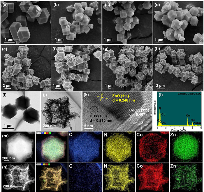
The morphologies of the ZIFs, ZIF derivatives and ternary composites were observed by using SEM and TEM images. From Fig. 2, the ZIF-8 and ZIF-67 both exhibits the rhombic dodecahedral shapes with well-defined edges and smooth faces (Figs. 2a and b), and after formation of ZIF-8@ZIF-67, the shape inherits from the morphology of ZIF-8 and shows clear rhombic dodecahedral structures (Fig. 2c). Notably, after introduction of CDs, the ZIF-8@CDs@ZIF-67 matrix still keeps the intact rhombic dodecahedral morphology (Fig. 2d), exhibiting that the presence of CDs has no effect on the initial shape of ZIFs. After pyrolysis of the ZIF precursors, ZIF-67 derived Co3O4 and ZIF-8 derived ZnO endow the well-defined sunken dodecahedron structures with rough surfaces (Figs. 2e and f). While core-shell ZnO@Co3O4 remains the sunken and rough dodecahedron structure with a diameter of approximately 2 µm (Fig. 2g). After combining with the CDs, the ZnO@CDs@Co3O4 indicates a regular sunken and rough dodecahedron structure with a more uniform distribution (Fig. 2h).
Figure 2
Figure 2.
SEM images of (a) ZIF-67, (b) ZIF-8, (c) ZIF-67@ZIF-8, (d) ZIF-8@CDs@ZIF-67, (e) Co3O4, (f) ZnO, (g) ZnO@Co3O4, (h) ZnO@CDs@Co3O4. TEM images of (i) ZIF-8@CDs@ZIF-67, (j) ZnO@CDs@Co3O4, HRTEM image of (k) ZnO@CDs@Co3O4, and (l) EDX pattern of ZnO@CDs@Co3O4. The corresponding elemental mapping images of (m) ZIF-8@CDs@ZIF-67, and (n) ZnO@CDs@Co3O4.
The TEM images of ZIF-8@CDs@ZIF-67 and ZnO@CDs@Co3O4 are shown in Figs. 2i and j. From TEM image of ZnO@CDs@Co3O4 in Fig. 2j, it is clear seen that the formed nanocages are composed of numerous tiny nanoparticles including ZnO, Co3O4 and CDs. The middle layer appears to be particularly clear attributed to the existence of CDs, suggesting the formation of sandwich structure. Further observation, the HRTEM image of ZnO@CDs@Co3O4 shows three distinct lattice spacings, which are indexed to those at 0.21, 0.25, and 0.48 nm ascribed to the (100) of CDs, (111) of ZnO and (111) of Co3O4, respectively (Fig. 2k) [31,29]. From the EDX spectra (Fig. 2l), it is clear that the ZnO@CDs@Co3O4 ternary composite shows the distributions of Zn, C, N, O, and Co elements, confirming the successful synthesis of the ZnO@CDs@Co3O4. The elemental mapping images of ZIF-8@CDs@ZIF-67 reveal that C, N, Zn, and Co elements are uniformly distributed on the ternary heterostructure, and it can be observed that Zn element is mainly distributed in the center and Co element exists in the periphery of the composite, clearly indicating ZIF-67 as outer layer coated on the ZIF-8 core (Fig. 2m). For ZnO@CDs@Co3O4 (Fig. 2n), the C element in the outer layer is remarkably reduced compared with ZIF-8@CDs@ZIF-67, and C element in the middle layer is reserved, demonstrating the formation of sandwich structure, in which the CDs act as a bridge between ZnO and Co3O4.
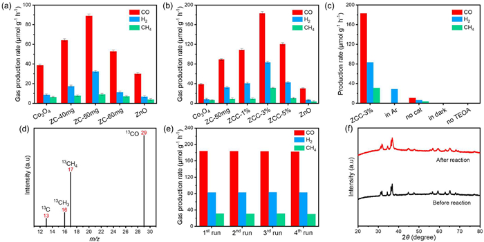
The photocatalytic CO2 performances of ZIFs, ZIF derivatives and ternary composites were evaluated in the TEOA/H2O/MeCN mixed solution under simulated solar light. The main CO, CH4 and H2 products were detected in this photocatalytic system. As displayed in Fig. 3a, the bare ZnO and Co3O4 exhibit the low performance, while ZnO@Co3O4 (ZC) composites indicate the improved photocatalytic CO2 reduction rate and the yield of CH4 (9.16 µmol g−1 h−1) and CO (89.06 µmol g−1 h−1) of ZnO@Co3O4–50 mg (ZC-50 mg) is the highest. Especially, ZnO@CDs@Co3O4 (ZCC) catalysts exhibit the further enhanced photocatalytic performances (Fig. 3b), and considering the effect of CDs loading on the performance, it is found that the highest CO yield of ZnO@CDs@Co3O4–3% (ZCC-3%) is 183.21 µmol g−1 h−1, which is 6.10 and 2.06 times that of pure ZnO and binary ZC, respectively. Besides, the highest AQY of ZCC-3% is up to 3.6% (Table S3 in Supporting information). By contrast, the ZIF-8@ZIF-67 (ZZ) composites exhibit the much lower performance (35.11 µmol g−1 h−1) than ZnO@Co3O4 under the same condition (Fig. S10 in Supporting information), indicating that the pyrolysis process is necessary. The control tests (Fig. 3c) and isotope tracer analysis (Fig. 3d) confirm that the carbonaceous reagents indeed originate from CO2 reduction. Fig. 3e shows the photostability of the optimal ZnO@CDs@Co3O4 composite by cyclic tests. The ZCC-3% retains the high photoreduction CO2 performance after four cycles, indicating the outstanding catalytic durability. Furthermore, the XRD pattern for ZnO@CDs@Co3O4 after the photocatalytic reaction is the same as the initial status, which verifies the high stability and recyclability of the samples (Fig. 3f).
Figure 3
Figure 3.
Production rate of CO, CH4 and H2 of (a) binary catalysts and (b) ternary catalysts. (c) Production of CO, CH4 and H2 under various reaction conditions. (d) 13C isotopic labeling experiment. (e) Stability tests of ZCC-3%. (f) XRD patterns of ZCC-3% before and after CO2 photoreduction tests.
The UV–vis DRS spectra were studied for the as-prepared ZnO, Co3O4, ZnO@Co3O4, and ZnO@CDs@Co3O4, as shown in Fig. S2a (Supporting information). The ZIF-derived Co3O4 indicates the broad absorption edge in the entire region, while ZnO exhibits an optical absorption edge around 400 nm and rarely absorbs visible light. The absorption edge of ZnO@Co3O4 presents an obvious red shift in comparison with bare ZnO, suggesting that ZnO@Co3O4 can absorb more visible light. After the introduction of the CDs, the absorption edge of ZnO@CDs@Co3O4 has no significant change compared with ZnO@Co3O4, probably due to CDs in the middle layer, in which the light absorption ability of CDs is inhibited by Co3O4 outer layer. Furthermore, from the Tauc plot (Fig. S2b in Supporting information), the band-gap energies (Eg) of Co3O4 and ZnO are estimated to be 1.86 and 3.12 eV [32–34].
To further explore the charge transfer of ZnO@CDs@Co3O4, the photoluminescence (PL) and time-resolved (TR)-PL spectra were conducted under 380 nm excitation in Figs. S2c and d (Supporting information) [35]. After loading with CDs, the decreased PL peak of ZnO@CDs@Co3O4 can be noticed, due to the remarkably improved separation efficiency of charge carriers. According to the double exponential fitting function, the average lifetimes of Co3O4 are shortened from 3.91 ns to 1.17 ns after formation of heterojunction. In addition, after combining with CDs, the average lifetime decreases sharply from 1.17 ns (ZnO@Co3O4) to 0.67 ns (ZnO@CDs@Co3O4), suggesing that the tenary heterostructure can significantly suppress the photoinduced electron-hole pairs recombination. The charge separation and transfer were further analyzed by photocurrent and EIS (Figs. S3a and b in Supporting information). The ternary composite exhibits the highest photocurrent, indicating that the loading of CDs can signicantly improve the separation efficiency of photogenerated carriers [36]. Meanwhile, the ZnO@CDs@Co3O4 exhibits the smallest arc radius compared with ZnO@Co3O4, Co3O4 and ZnO, suggesting the highest electrical conductivity of ternary composite in the EIS Nyquist diagram [37].
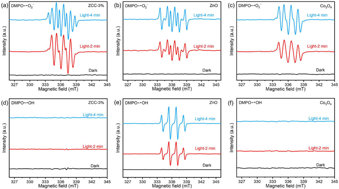
The M-S curves (Figs. S3c and d in Supporting information) reveal that Co3O4 possesses the p-type semiconductor ability, while ZnO belongs to an n-type semiconductor. Since the EFB (vs. NHE) is about 0.2 V more positive than EFB (vs. Ag/AgCl) [38], the EFB of Co3O4 and ZnO is 0.93 and −0.55 V vs. NHE, respectively. For an n-type semiconductor, it is widely accepted that EFB is about 0.1 V positive than ECB, while for a p-type semiconductor, its EVB is 0.1 V positive than EFB [39]. Therefore, the EVB of Co3O4 is about 1.03 V vs. NHE, and the ECB value of ZnO is −0.65 V vs. NHE. Based on the formula ECB = EVB - E [40], the ECB value of Co3O4 is −0.83 V vs. NHE, and the EVB of ZnO is 2.47 V vs. NHE. To gain a deeper understanding of the charge transfer pathways within the heterojunction, we examined the EPR spectra of Co3O4, ZnO, and ZCC-3% using 5,5-dimethyl-1-pyrroline-N-oxide to detect DMPO~•OH and DMPO~•O2− signals, respectively (Figs. 4a–c). As illustrated in Figs. 4d–f, the peaks attributed to DMPO-•OH signals are detected for ZnO, while no significant signals are observed for Co3O4 and ZCC-3%, indicating that the holes are accumulated on the EVB of Co3O4 in the p-n heterojunction.
Figure 4
Figure 4.
DMPO~•O2− spin-trapping EPR spectra of (a) ZCC-3%, (b) ZnO and (c) Co3O4. DMPO~•OH spin-trapping EPR spectra of (d) ZCC-3%, (e) ZnO and (f) Co3O4.
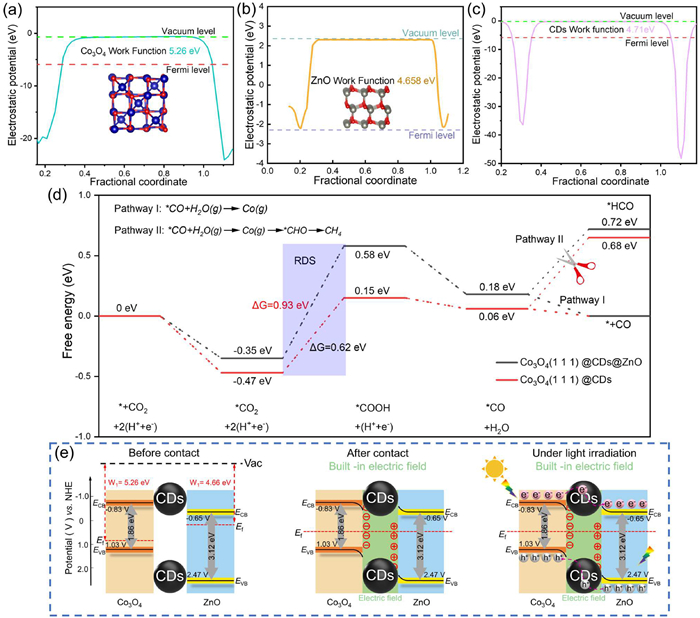
Additionally, DFT simulations were used to study the charge transfer direction of ZnO@CDs@Co3O4 heterostructure (Figs. 5a–c). Since the work function values of ZnO and Co3O4 are 4.71 and 5.26 eV, respectively, the electrons in ZnO are moved to Co3O4 until the Fermi level (Ef) reaches the equilibrium. After formation of heterojunction (Fig. 5e), the band of ZnO bends upward and that of Co3O4 bends downward, resulting in the construction of built-in electric field. Importantly, the co-catalyst CDs in the heterostructure can be considered as a good bridge to facilitate the charge transfer between Co3O4 and ZnO. After illumination, the photoinduced electrons are transferred from ECB of Co3O4 to that of ZnO, while holes are migrated from EVB of ZnO to that of Co3O4, in which the CDs accelerate the charge migration.
Figure 5
Figure 5.
Work functions of (a) Co3O4, (b) ZnO and (c) CDs. (d) The calculated potential free-energy diagrams for CH4 and CO formation. (e) The proposed mechanism of Co3O4@CDs@ZnO catalyst.
To investigate the mechanism for superior CO selectivity, the charge free energy for photocatalytic CO2 reduction over pristine Co3O4 and ZnO@CDs@Co3O4 were carried out (Fig. 5d). Obviously, the free energy at each stage for heterostructure is lower than that of Co3O4, suggesting that CO2 photoreduction prefers to occur in ZnO@CDs@Co3O4 under natural conditions. It can be seen that the formed *COOH intermediate acts as the rate-limiting step to sequentially produce CO and CH4, and the composite presents the better capability to adsorb-activate CO2 and generate the key intermediate [41]. Besides, the free energy of *+CO is much lower than that of *HCO, indicating that the CO is easier to be generated compared with CH4 in this catalyst system, in agreement with the photocatalytic CO2 performance.
In summary, we have successfully synthesized the novel ZnO@CDs@Co3O4 heterojunction, and explored its photocatalytic performance for CO2 reduction. The ZIF-derived ZnO@CDs@Co3O4 nanocage with sunken dodecahedron exhibits abundant active sites and close contact, in which CDs as middle layer between ZnO and Co3O4 construct the sandwich-structure. Besides, the formed p-n heterojunction by coating Co3O4 on ZnO exhibits the re-established built-in electric fields, and CDs with electron transfer/reservoir property can facilitate the charge transfer, thereby boosting CO2 photoreduction and stability. As expected, the ternary catalyst exhibits the maximum (CO + CH4) yield of 214.53 µmol g−1 h−1 with TEOA, which is 6.32-fold that of bare ZnO and 2.18-fold that of ZnO@Co3O4. This study provides an effective strategy to fabricate a CDs-based sandwich heterostructure for highly active CO2 photoreduction.
Acknowledgments
This work was supported by the National Natural Science Foundation of China (Nos. 51725204, 21771132, 51972216, 52041202), Qinglan Project Foundation of Jiangsu Province, Zhejiang Province Key Research and Development Project (No. 2023 C01191).
Supplementary materials
Supplementary material associated with this article can be found, in the online version, at doi:10.1016/j.cclet.2023.109064.
Figure 1
(a) XRD patterns of Co3O4, ZnO, ZnO@Co3O4, and ZnO@CDs@Co3O4 composite. (b) Nitrogen adsorption-desorption isotherms of Co3O4, ZnO@Co3O4, and ZnO@CDs@Co3O4. XPS spectra of Co3O4, ZnO, ZnO@Co3O4, and ZnO@CDs@Co3O4: (c) Co 2p and (d) Zn 2p.
Figure 2
SEM images of (a) ZIF-67, (b) ZIF-8, (c) ZIF-67@ZIF-8, (d) ZIF-8@CDs@ZIF-67, (e) Co3O4, (f) ZnO, (g) ZnO@Co3O4, (h) ZnO@CDs@Co3O4. TEM images of (i) ZIF-8@CDs@ZIF-67, (j) ZnO@CDs@Co3O4, HRTEM image of (k) ZnO@CDs@Co3O4, and (l) EDX pattern of ZnO@CDs@Co3O4. The corresponding elemental mapping images of (m) ZIF-8@CDs@ZIF-67, and (n) ZnO@CDs@Co3O4.
Figure 3
Production rate of CO, CH4 and H2 of (a) binary catalysts and (b) ternary catalysts. (c) Production of CO, CH4 and H2 under various reaction conditions. (d) 13C isotopic labeling experiment. (e) Stability tests of ZCC-3%. (f) XRD patterns of ZCC-3% before and after CO2 photoreduction tests.
Figure 5
Work functions of (a) Co3O4, (b) ZnO and (c) CDs. (d) The calculated potential free-energy diagrams for CH4 and CO formation. (e) The proposed mechanism of Co3O4@CDs@ZnO catalyst.

 DownLoad:

 下载:
下载:


 下载:
下载:
