Figure 1.
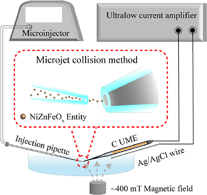
Schematic illustration of ultrasensitive electrochemical measurement of single NiZnFeOx entities by using a microjet collision method under an external magnetic field.

Water electrolysis has been regarded as a promising way for the source of a viable and sustainable hydrogen [1,2]. Typically, hydrogen production efficiency is limited by the sluggish reaction kinetics in the oxygen evolution reaction, which is typically considered the barrier for overall water splitting, as a slow and energy-demanding, four-electron process [3,4]. In the past decades, exploring new high efficiency electrocatalysts for OER has been of ongoing interest [5,6]. For example, defect-rich transition metal catalysts or phase-modulation of transition metal nanocrystals anchored on elements-doped carbon substrates were designed to efficiently enhance OER performance [7–9]. Very recently, theoretical calculations and experimental measurements have revealed that the magneto-enhancement is being considered as a potential strategy to speed up the spin-restricted water oxidation [10–12]. A very interesting work to boost OER efficiency comes from direct magnetic enhancement of nickel iron oxide in alkaline media just by simply moving a permanent magnet next to the anodic compartment [13]. Although considerable research efforts have been devoted to the design and development of OER electrocatalysts with both remarkable activity and high stability [14–16], substantial enhancement of OER performance remains a big challenge. This is because that the electrocatalytic performance exhibits a strongly dependence on not only the catalysts’ structure but also their assembly process [17–19]. It is found that an inappropriate assembly of ensemble measurements could decrease the electrocatalytic performance [20–22], resulting in obscuring the structure-activity relationship. Therefore, measuring the intrinsic activities of catalysts at single entity level enables the roles of catalyst structure to be quantified [23,24].
Single entity electrochemistry, such as stochastic collision electrochemistry and scanning electrochemical cell microscopy, is a powerful method to investigate the electrochemical behaviors of an individual entity (a nanoparticle, a cell, a molecule, etc.) at a nano/ultramicroelectrode, avoiding inhomogeneous averaging effect in ensemble experiment [25–27]. Recently, stochastic collision electrochemical measurements have attracted considerable attention to conveniently measure the transient current responses of individual entities during their collisions at an ultramicroelectrode (UME) [28–31]. It is readily accessible to identify their intrinsic activities of individual catalysts, which can hardly be dissected from additives or assembly by the ensemble measurements [32,33]. Here, we present an investigation of the magnetic electrocatalysts NiZnFeOx from bulk materials, single agglomerations to single NPs to reveal the trends for the OER performance (Fig. 1). We compare the onset potential and the resulting OER activities for these catalysts with and without a moderate magnetic field. We find the OER activity and the magnetic enhancement to be sensitively dependent on the dispersion degrees of the NiZnFeOx NPs. DFT calculations also confirm the monodispersed NiZnFeOx NPs with spin alignment under a moderate magnetic field, facilitating the OER performance. Our results further demonstrate that the monodispersed NiZnFeOx NPs onto the carbon walls of ordered mesoporous framework show excellent magnetic enhancement and low onset potential toward OER.
Because the magneto-enhancement is proportional to the magnetic properties of the catalysts, the highly magnetic iron-nickel oxide NiZnFeOx was selected as the OER catalyst in our experiment. The magnetic properties are dependent on Ni and Fe elements and the Ni is the active site [34]. A representative transmission electron microscopy (TEM) image reveals that as-prepared NiZnFeOx NPs possess the mean diameter measured from approximately 200 randomly selected particles to be 7 nm (Fig. S1 in Supporting information). We focused on the electrochemical oxygen evolution to investigate the response of a NiZnFeOx/Ni-foam anode in an alkaline liquid electrolyte (1 mol/L KOH solution) cell equipped with a platinum mesh cathode and an Ag/AgCl (3.5 mol/L KCl) reference electrode under a magnetic field. In this work, NiZnFeOx NPs were dispersedly decorated on a Ni-foam substrate by direct magnetic interaction via simple one-step sonication for 15 min. Scanning electron microscopy (SEM) images of the decorated Ni-foam electrode show the relatively rough surface and the assembled particles on the skeleton surface, confirming the presence of the NiZnFeOx NPs attached to the flat Ni-foam surface (Fig. 2a). The polarization curves (linear sweep voltammetry, LSV) of the NiZnFeOx/Ni-foam were examined with and without a magnetic field by approaching a commercial neodymium permanent magnet of ~400 mT. As expected, current density gradually increased with the potential getting higher (Fig. 2b, black line). When a magnetic field was applied, the same basal current appeared before ~1.50 V vs. the reversible hydrogen electrode (RHE) and a positive effect of the external magnetic field was observed at > 1.50 V vs. RHE (Fig. 2b, red line). The appearance of a magnetic enhanced current (magnetocurrent) above the onset potential reaches higher currents at any given potential under the applied magnetic field. The magnetocurrent can be calculated by Eq. 1:
|
|
(1) |
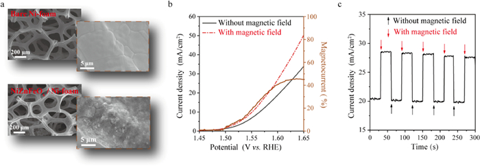
where J(Mon) and J(Moff) represent the current density with and without magnetic field, respectively. The magnetic enhancement of NiZnFeOx/Ni-foam, normalized by the basal electrocatalytic performance, reaches a maximum 42% at ~1.60 V vs. RHE. After this threshold, the relative magnetocurrent decreased, which was assigned to the diffusion limitations provoked by intense oxygen bubbling. Moreover, we performed a pulsed magneto-chronoamperometry experiment at a constant potential of 1.60 V vs. RHE for the NiZnFeOx/Ni–foam electrode. By simple employment of an external magnetic field, the current density is enhanced instantly (Fig. 2c). This is because that the magnetic field effectively reorients the spins and induces the spin alignment of the NiZnFeOx catalysts, facilitating the charge transfer between the adsorbed oxygen intermediates and the metal active sites through spin polarization to promote the properties of OER [35]. Additionally, the maximum magnetocurrent of bare Ni-foam is only 10% at ~1.60 V vs. RHE, much smaller than the NiZnFeOx/Ni-foam (Fig. S2 in Supporting information), indicating significant magnetocurrent is indeed attributed to the NiZnFeOx attached on the Ni-foam substrate under the external magnetic field. Thus, the OER performance of NiZnFeOx catalysts can be promoted under a proper magnetic field.
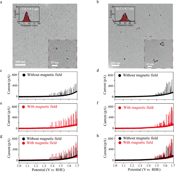
As well-known, OER performance and magnetocurrent enhancement using the ensemble LSV measurement would be affected by the assembly process of NiZnFeOx NPs on Ni-foam substrate [17–22]. To further quantify the intrinsic properties of this catalyst, we employed a stochastic collision electrochemical method to examine OER performance of NiZnFeOx at single entity level. In this study, a facile step-wise centrifugation method was introduced to separate the NiZnFeOx entities at a variety of centrifugation speeds [36]. Firstly, the large aggregated particles were removed by centrifuging at 4000 rpm for 40 min. The top layer was sequentially centrifuged at speeds of 8000 rpm, 10,000 rpm, and 14,000 rpm for 1 h each. Correspondingly, NiZnFeOx catalysts were separated into three groups depending on size, along with the average size of 7 nm, 30 nm, and 105 nm, respectively (Figs. 3a and b, Fig. S3 in Supporting information). TEM images indicate that the separated NiZnFeOx entities are relatively size uniform and well-dispersed.
Having obtained different groups of NiZnFeOx entities, we attempted to perform single entity electrochemical measurements in 0.1 mol/L KOH solution. Here, we used a carbon fiber UME with a diameter of 7.0 µm (C UME, Fig. S4 in Supporting information) as an inert electrode surface to achieve the ultrasensitive measurement of individual collision events. To guarantee the electrochemical measurement of highly magnetic NiZnFeOx catalysts occurred at single entity level under a moderate magnetic field, we employed the “microjet collision method” to study the OER process across individual NiZnFeOx entities at the C UME. This method uses a pressure-driven flow to deliver NiZnFeOx entities from a glass micropipette onto a working electrode in very close proximity (few µm separation). In brief, an injection micropipette filled with the NiZnFeOx entities is connected to a Femtojet microinjector, and attached to a micropositioner. The C UME is then connected to a separate micropositioner that directly opposites from the micropipette’s position. The collision events would be continuously recorded when individual NiZnFeOx entities under pressure-driven flow are directly injected one by one towards the surface of C UME. In this way, an extreme low concentration of entities in micropipette and a microinjection strategy were exploited during the electrochemical measurement, avoiding the aggregation of NiZnFeOx entities on C UME even under an applied magnetic field [37].
To ensure the collision events occurred at single entity level, the well-dispersed NiZnFeOx NPs (size: 7 nm) and NiZnFeOx agglomerations (size: 30 nm) were diluted to tens of pmol/L level. Significant current transients were observed for OER catalyzed by both individual NPs and agglomerations in 0.1 mol/L KOH solution upon their collisions at the C UME surface. As shown in Figs. 3c and d, NiZnFeOx NPs begin to catalyze OER at ~1.35 V vs. RHE during the voltage sweep while the onset potential of individual agglomerations is up to ~1.45 V vs. RHE. In this recording, the current contribution of Ni oxidation is negligible because the theoretical currents for a total oxidation of a single NiZnFeOx NP (7 nm) and NiZnFeOx agglomeration (30 nm) should be less than 1 pA and 20 pA, respectively, which cannot be resolved from the baseline noise. Thus, the observed current transients are attributed to the OER process of individual NiZnFeOx entities. Interestingly, although the NiZnFeOx agglomerations supposed to possess larger geometrical surface area, single NiZnFeOx NPs show a higher catalytic current at the onset potential than that of single agglomerations. Moreover, the current of single NiZnFeOx NPs maintain constant within a typical variation as function of the applied potential (Fig. 3c), while the current of single NiZnFeOx agglomerations is dramatically enhanced as the applied potential increased (Fig. 3d) [38]. Single entity electrochemical results indicate that the OER activities of NiZnFeOx are strongly influenced by their aggregation state. This could be attributed to size-dependent (1) electrical conductivity and (2) surface spin state of NiZnFeOx catalysts. On the one hand, the electrical conductivity gradually decreases with increasing particle size [39]. At low potential, NiZnFeOx agglomerations, which are in direct contact with the C UME during their collision process, can only be partially activated for OER process due to the electrical conductivity limitations [40]. At higher potentials, the conductivity of NiZnFeOx agglomerations increases, resulting in a larger fraction of the catalysts participating in OER catalysis. Indeed, the amperometric current-time curves of larger NiZnFeOx agglomerations (size: 105 nm) showed a significant potential dependence of OER activities (Fig. S5 in Supporting information). Initially, the current amplitude of individual 105 nm NiZnFeOx agglomerations is only ~100 pA at the applied potential of 1.50 V vs. RHE. With the increasing of applied potential, the current amplitude dramatically increased to ~400 pA and ~1000 pA at 1.60 V and 1.70 V vs. RHE, respectively. Therefore, a higher applied potential is needed for larger NiZnFeOx agglomerations to drive or activate their OER process. On the other hand, the spin state can be also regulated by the morphological size of NiZnFeOx catalysts [41]. The increase of high spin electrons at the surface of the NiZnFeOx caused by the decrease of particle size enables generating a stronger unblocked spin channel between the metal active sites and the oxygen related adsorbates [42,43]. This spin channel realizes a proper oxygen intermediate adsorption and promotes the electron transfer for the small sized NiZnFeOx NPs at a low potential. In contrast, the low spin state for metal active sites at the surface of the aggregated NiZnFeOx catalysts makes it need to overcome the stronger surface reaction energy barrier for activating OER, leading to the higher potential as driving force to boost OER activity.
Next, we turned our attention to the magnetic enhancement in OER activity of single NiZnFeOx entities. The enhanced current was observed for single NiZnFeOx NPs and agglomerations at any applied potential under the external magnetic field of ~400 mT (Figs. 3e and f). The overlapped LSV curves with and without magnetic field show a relatively significant magnetocurrent effect at the low potential, while the magnetic enhancement reached a maximum value at a certain potential and the magnetocurrent decreased as the applied potential further increased (Figs. 3g and h). This is because that OER efficiency of the NiZnFeOx catalysts would be significantly boosted by both the driving of a high potential and the implementation of a magnetic field, resulting in the formation of oxygen bubbles at the surface of NiZnFeOx catalysts. Accordingly, the diffusion limitation was caused by the oxygen gas bubbling, thus decreasing the magnetocurrent effect after the threshold potential [12,44].
To give a more clear description of magnetic enhancement effect, we performed the chronoamperometric experiments of single NiZnFeOx NPs and agglomerations at the constant potentials of 1.40 V and 1.50 V vs. RHE, respectively, where the maximum magnetocurrents were correspondingly observed. Under the periodic magnetic field, the current responses switch between high and low state, displaying good reversibility (Figs. 4a and b). To exclude the magnetic field-induced NiZnFeOx aggregation during single entity electrochemical measurement, the collision frequency of individual entities was further examined. During two periodic measurement processes with and without magnetic field, the experimental collision frequencies of NiZnFeOx NPs at each switch are 26.33 s−1, 26.32 s−1, 25.33 s−1, and 24.67 s−1, respectively (Fig. S6 in Supporting information, black curve). Meanwhile, the corresponding collision frequencies of NiZnFeOx agglomerations are 19.00 s−1, 21.00 s−1, 19.67 s−1, and 20.67 s−1, respectively (Fig. S6 in Supporting information, red curve). Notably, the collision frequencies of individual events are strongly independent on the magnetic perturbation, indicating no aggregation appears during the entire electrochemical measurement process under the magnetic field. In this study, the dilute concentration and the microinjection strategy succeed in preventing the aggregation of NiZnFeOx entities near the C UME under the magnetic field. Moreover, the current increased immediately at an applied magnetic field of ~400 mT. While the magnetic field is moved away, the current amplitude instantly decreases to the same state without applying the magnetic field. This immediate effect of magnetic perturbation is ascribed that NiZnFeOx as the spin polarizer favors the parallel alignment of oxygen radicals during the formation of the O—O bond along with the applied external magnetic field, promoting the OER activity [45,46].

It was worth mentioning that there is a strong magnetocurrent enhancement above 118% for NiZnFeOx NPs, while current increment of 80% is found for NiZnFeOx agglomerations (Figs. 4c and d). Notably, the magnetocurrent enhancements of single NiZnFeOx entities are far greater than that of the bulk NiZnFeOx on Ni-foam (42%). The difference of the enhancement of OER magnetocurrents suggests that three groups of NiZnFeOx catalysts exhibit different spin polarization degrees under the same magnetic field. Previous literatures reported the saturation magnetization decreased with the decrease of NiZnFeOx size [47]. When the strength of the applied external magnetic field is larger than the saturation magnetization, all the spins would point to the same direction as the external magnetic field [48]. Thus, the spins in monodispersed NiZnFeOx NPs are more favorable to totally reorient with the direction of the external magnetic field under the external magnetic field in comparison with those of NiZnFeOx agglomerations and the NiZnFeOx/Ni-foam (Fig. 5a). Therefore, small, monodispersed NiZnFeOx NPs have a high spin polarization degree, which can facilitate the electron transfer, resulting in a higher OER activity. However, a disordered surface spin structure under a moderate magnetic field is proved for the high saturation magnetization of the aggregated NiZnFeOx system, increasing electron repulsion during the OER processes. Moreover, the aggregated NiZnFeOx system would generate a tiny magnetic field in a different direction from the external magnet, which counteracts the external magnet intensity, further decreasing the magnetic enhancement effect.

Furthermore, we explore the utility of theoretical investigation by DFT calculations for studying OER process on NiZnFeOx surfaces without and with spin alignment. In view that in alkaline solution, OER generally occurs with lattice oxygen involved, and thus in this work we only consider the lattice oxygen-mediated mechanism (LOM) for OER. Considering the Ni atoms are the active sites for OER, a Ni-rich NiZnFeOx surface was modelled as shown in Fig. S7 (Supporting information). Figs. 5b and c show the computed reaction energies of each dehydrogenation step in OER at pH 0 and potential = 0 vs. SHE. It is revealed that the dehydrogenation of the first OH* is the rate limiting step for both of spin aligned and unaligned NiZnFeOx surfaces. Notably, the computed overpotential of OER is as large as 1.45 eV when the spins are not aligned, indicating the OER is hard to proceed at low overpotential conditions, while the overpotential is significantly decreased to only 0.46 eV after spin alignment. We attribute this overpotential difference to the difference in the binding energy of O on the surfaces in two spin conditions. It is known that each O has two unpaired electrons with same spin, as represented in Fig. 5d, and we can find that each surface O involved in the OER binds with two Ni atoms. Theoretically, O should bind more strongly on the surface when the spins of Ni are aligned, because at that condition both Ni-O bonds are formed without inversing the spin of the electron, which is consistent with the energy calculated by DFT. DFT calculations prove that a totally spin polarization facilitates the OER process. Compared to the NiZnFeOx agglomerations with anti-parallel couplings, spins in monodispersed NiZnFeOx NPs are more favorable to totally align under the external magnetic field. Therefore, we envisage that the well-dispersion of NiZnFeOx catalysts on the substrate may improve the magnetic-assisted water oxidation in ensemble electrochemical measurement.
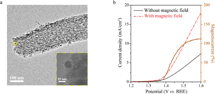
Encouraged by the interesting results of our single entity electrochemical measurement and DFT calculations, we further performed the OER test by supporting monodispersed NiZnFeOx NPs onto the carbon walls of ordered mesoporous framework. TEM image of NiZnFeOx/carbon obviously shows that the NiZnFeOx NPs having uniform sizes of 7–8 nm are highly dispersed on ordered mesoporous carbon framework and supported onto the carbon walls (Fig. 6a). LSV polarization curves in Fig. 6b suggest that the NiZnFeOx/carbon electrode possess the low onset potential of 1.40 V vs. RHE for water oxidation. On application of the magnetic field, the current density significantly enhanced, reaching a maximum 110% magnetic enhancement at ~1.60 V vs. RHE. Therefore, an assembly strategy of well-dispersed NiZnFeOx NPs onto ordered mesoporous carbon framework would result in a sharp increase in their OER and magnetic enhancement effect, which is consistent with the results of magnetic enhancement effect for monodispersed NiZnFeOx NPs.
In conclusion, we study the OER performance on the NiZnFeOx catalyst with and without magnetic field from bulk materials, single agglomerations to single NPs. We find the aggregation degree of NiZnFeOx catalysts would change the electrical conductivity and the surface spin state, resulting in affecting their OER activities. Our single entity electrochemical results demonstrate that the OER performance and the magnetic enhancement are significantly promoted by the well-dispersion of NiZnFeOx catalysts, which is further confirmed by the DFT calculations and ensemble measurement of monodispersed NiZnFeOx NPs onto ordered mesoporous carbon framework. Therefore, incorporating well-dispersed catalysts on substrate is desirable for magnetic-assisted OER. This work provides new insights in promoting the magnetic enhancement effect of OER performance based on the intrinsic properties of single entity, resulting in quantifying structure–activity relationship of catalysts.
The authors declare that they have no known competing financial interests or personal relationships that could have appeared to influence the work reported in this paper.
This work was supported by the Major Research Project (No. 92061108), the National Natural Science Foundation of China (No. 22272052), Shanghai Municipal Science and Technology Major Project (No. 2018SHZDZX03), Xiamen University Opening Project of PCOSS (No. 201901) and Yongjiang Talent Introduction Programme (No. 2021A-115-G).
Supplementary material associated with this article can be found, in the online version, at doi:
Z.W. Seh, J. Kibsgaard, C.F. Dickens, et al., Science 355 (2017) 4998. doi: 10.1126/science.aad4998
S.Y. Tee, K.Y. Win, W.S. Teo, et al., Adv. Mater. 4 (2017) 1600337.
F. Chen, Z. Zhang, W. Liang, et al., Chin. Chem. Lett. 33 (2022) 1395–1402. doi: 10.1016/j.cclet.2021.08.019
B. You, M.T. Tang, C. Tsai, et al., Adv. Mater. 31 (2019) 1807001. doi: 10.1002/adma.201807001
Z.F. Huang, J. Wang, Y. Peng, et al., Adv. Energy Mater. 7 (2017) 1700544. doi: 10.1002/aenm.201700544
S. Anantharaj, S.R. Ede, K. Sakthikumar, et al., ACS Catal. 6 (2016) 8069–8097. doi: 10.1021/acscatal.6b02479
S. Zhao, M. Li, M. Han, et al., Adv. Funct. Mater. 28 (2018) 1706018. doi: 10.1002/adfm.201706018
L. Wang, J. Fan, Y. Liu, et al., Adv. Funct. Mater. 31 (2021) 2010912. doi: 10.1002/adfm.202010912
W. Hu, M. Zheng, H. Duan, et al., Chin. Chem. Lett. 33 (2022) 1412–1416. doi: 10.1016/j.cclet.2021.08.025
Y. Li, L. Zhang, J. Peng, W. Zhang, K. Peng, J. Power Sources 433 (2019) 226704. doi: 10.1016/j.jpowsour.2019.226704
G. Zhou, P. Wang, H. Li, et al., Nat. Commun. 12 (2021) 4827. doi: 10.1038/s41467-021-25095-4
J. Yao, W. Huang, W. Fang, et al., Small Methods 4 (2020) 2000494. doi: 10.1002/smtd.202000494
F.A. Garcés-Pineda, M. Blasco-Ahicart, D. Nieto-Castro, N. López, J.R. Galán– Mascarós, Nat. Energy 4 (2019) 519–525. doi: 10.1038/s41560-019-0404-4
H. Yan, Y. Xie, A. Wu, et al., Adv. Mater. 31 (2019) 20191174.
D. Böhm, M. Beetz, M. Schuster, et al., Adv. Funct. Mater. 30 (2020) 1906670. doi: 10.1002/adfm.201906670
J. Gu, S. Magagula, J. Zhao, Z. Chen, Small Methods 11 (2019) 1800550.
C. Sun, J. Yang, Z. Dai, et al., Nano Res. 9 (2016) 1300–1309. doi: 10.1007/s12274-016-1025-x
L. Chen, Y. Guo, H. Wang, et al., J. Mater. Chem. A 6 (2018) 4636–4641. doi: 10.1039/C7TA11078B
X. Lu, M. Li, Y. Peng, et al., J. Am. Chem. Soc. 143 (2021) 16925–16929. doi: 10.1021/jacs.1c08592
T. Wang, L. Liu, Z. Zhu, et al., Energy Environ. Sci. 6 (2013) 625–633. doi: 10.1039/C2EE23513G
C. Yu, Z. Liu, X. Han, et al., Carbon 110 (2016) 1–7. doi: 10.1016/j.carbon.2016.08.020
D.Y. Chung, S.K. Park, Y.H. Chung, et al., Nanoscale 6 (2014) 2131–2136. doi: 10.1039/C3NR05228A
T. Quast, H.B. Aiyappa, S. Saddeler, et al., Angew. Chem. Int. Ed. 60 (2021) 3576–3580. doi: 10.1002/anie.202014384
R. Chen, S. Liu, Y. Zhang, Mater. Horiz. 10 (2023) 52–64. doi: 10.1039/D2MH01143C
L.A. Baker, J. Am. Chem. Soc. 140 (2018) 15549–15559. doi: 10.1021/jacs.8b09747
H. Ren, M.A. Edwards, Curr. Opin. Electrochem. 25 (2021) 100632. doi: 10.1016/j.coelec.2020.08.014
Y. Shan, X. Deng, X. Lu, et al., Chin. Chem. Lett. 33 (2022) 5158–5161. doi: 10.1016/j.cclet.2022.03.010
X. Xiao, A.J. Bard, J. Am. Chem. Soc. 129 (2007) 9610–9612. doi: 10.1021/ja072344w
B.J. Plowman, N.P. Young, C. Batchelor-McAuley, R.G. Compton, Angew. Chem. Int. Ed. 128 (2016) 7116–7119. doi: 10.1002/ange.201602867
H. Li, X. Zhang, Z. Sun, W. Ma, J. Am. Chem. Soc. 144 (2022) 16480–16489. doi: 10.1021/jacs.2c05299
Z. Sun, Z. Gu, W. Ma, Anal. Chem. 95 (2023) 3613–3620. doi: 10.1021/acs.analchem.2c04309
A.E. Arrassi, Z. Liu, M.V. Evers, et al., J. Am. Chem. Soc. 141 (2019) 9197–9201. doi: 10.1021/jacs.9b04516
P.A. Defnet, C. Han, B. Zhang, Anal. Chem. 91 (2019) 4023–4030. doi: 10.1021/acs.analchem.8b05463
P. Thakur, S. Taneja, D. Chahar, B. Ravelo, A. Thakur, J. Magn. Magn. Mater. 530 (2021) 167925. doi: 10.1016/j.jmmm.2021.167925
X. Ren, T. Wu, Y. Sun, et al., Nat. Commun. 12 (2021) 2608. doi: 10.1038/s41467-021-22865-y
J. Kang, H. Lee, Y.N. Kim, et al., Nanoscale Res. Lett. 8 (2013) 1–7. doi: 10.1186/1556-276X-8-1
F. Ludwig, C. Balceris, T. Viereck, et al., J. Magn. Magn. Mater. 427 (2017) 19–24. doi: 10.1016/j.jmmm.2016.11.113
M. Du, Y. Meng, G. Zhu, et al., Nanoscale 12 (2020) 22014–22021. doi: 10.1039/D0NR05780K
S.A. Makhlouf, M.A. Kassem, M.A. Abdel-Rahim, J. Mater. Sci. 44 (2009) 3438–3444. doi: 10.1007/s10853-009-3457-0
S. Zou, M.S. Burke, M.G. Kast, et al., Chem. Mater. 27 (2015) 8011–8020. doi: 10.1021/acs.chemmater.5b03404
S. Zhou, X. Miao, X. Zhao, et al., Nat. Commun. 7 (2016) 1–7.
J. Hwang, R.R. Rao, L. Giordano, et al., Science 358 (2015) 751–756.
Y. Sun, X. Ren, S. Sun, et al., Angew. Chem. Int. Ed. 60 (2021) 14536–14544. doi: 10.1002/anie.202102452
S.K. Jown, A.J. Bard, J. Am. Chem. Soc. 134 (2012) 7102–7108. doi: 10.1021/ja300894f
Y. Sun, S. Sun, H. Yang, et al., Adv. Mater. 32 (2020) 2003297. doi: 10.1002/adma.202003297
X. Li, Z. Cheng, X. Wang, Electrochem. Energy Rev. 4 (2021) 136–145. doi: 10.1007/s41918-020-00084-1
H.M. Lu, W.T. Zheng, Q. Jiang, J. Phys. D 40 (2007) 320–325. doi: 10.1088/0022-3727/40/2/006
L. Wang, H. Yang, J. Yang, et al., Ionics 22 (2016) 2195–2202. doi: 10.1007/s11581-016-1746-6

Figure 1 Schematic illustration of ultrasensitive electrochemical measurement of single NiZnFeOx entities by using a microjet collision method under an external magnetic field.

Figure 2 (a) SEM images of the bare Ni-foam (top) and the Ni-foam decorated with NiZnFeOx (bottom). (b) LSV curves of NiZnFeOx/Ni-foam in 1 mol/L KOH solution at a scan rate of 10 mV/s. The magnetocurrent component is represented in brown. (c) Chronoamperometric experiment was performed at a constant potential of 1.60 V vs. RHE for the NiZnFeOx/Ni-foam electrodes under pulsed turn-on and turn-off magnetic field.

Figure 3 TEM images and size distributions of NiZnFeOx NPs (7 nm, a) and agglomerations (30 nm, b). LSV curves of individual NiZnFeOx NPs (c, e, g) and agglomerations (d, f, h) collision at the C UME in 0.1 mol/L KOH solution with and without an applied ~400 mT magnetic field at a scan rate of 50 mV/s.

Figure 4 Chronoamperometric current-time curves of individual NiZnFeOx NPs (7 nm, a) at 1.40 V vs. RHE and NiZnFeOx agglomerations (30 nm, b) at 1.50 V vs. RHE at a C UME in 0.1 mol/L KOH solution. Right panels: close-ups of the representative current traces. Histograms showing the distributions of the current amplitude of NiZnFeOx NPs (7 nm, c) and NiZnFeOx agglomerations (30 nm, d).

Figure 5 (a) Schematic illustration of different spin polarization degrees under the same magnetic field. (b) Spin unaligned and (c) spin aligned OER pathways and the reaction energy of each elemental step is calculated. (d) Comparison of the bonding between O and Ni3+ when spin aligned and unaligned.

Figure 6 (a) TEM image of monodispersed NiZnFeOx NPs on ordered mesoporous carbon framework. Inset: High resolution-TEM image of single NiZnFeOx NP on ordered mesoporous carbon framework. (b) LSV curves of NiZnFeOx/carbon in 1 mol/L KOH solution at a scan rate of 10 mV/s. The magnetocurrent component is represented in brown.

 扫一扫看文章

扫一扫关注我们
 DownLoad:
 下载:
下载:
 下载:
下载: