Figure 1.
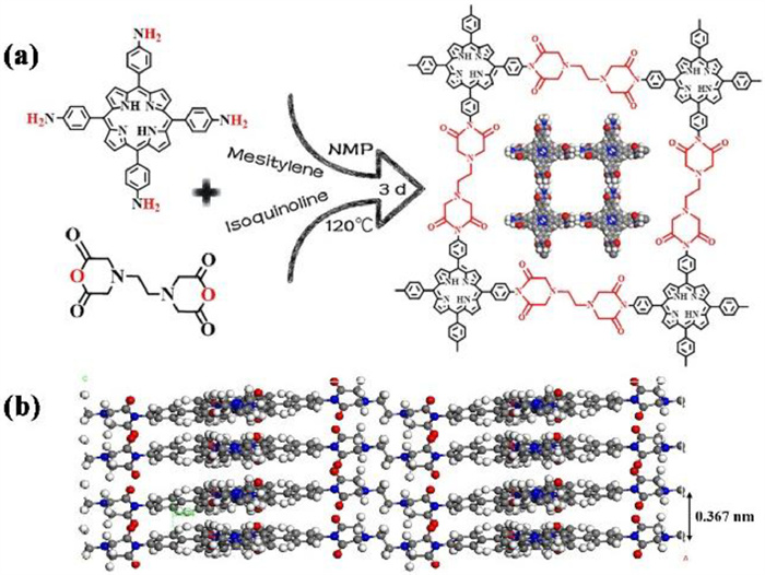
(a) Schematic representation of the synthesis processes of PI-COF. (b) Stacking distance between the two adjacent layers (O, red; N, blue; C, gray).
Imide-based covalent organic framework with excellent cyclability as an anode material for lithium-ion battery
Yue Qian , Zhoujia Liu , Haixin Song , Ruize Yin , Hanni Yang , Siyang Li , Weiwei Xiong , Saisai Yuan , Junhao Zhang , Huan Pang

With the increasing demand for low-carbon lifestyles, the development of clean and sustainable energy has become a pressing need. Lithium-ion batteries (LIBs), as a representative of new energy, have garnered much attention and have been widely used in new energy vehicles and portable electronic devices [1]. However, the limited reserves and high cost of non-renewable lithium-containing transition metal-based electrode materials restrict their large-scale applications and cause environmental problems, such as water and soil pollution [2–5]. Therefore, the development of high-performance, sustainable, and eco-friendly electrode materials is of utmost importance for the practical applications of Li-ion batteries.
In recent years, a large number of organic compounds, such as organic carbonyl (C=O) compounds [6] and quinone/phenoxide derivatives [7,8], have been explored as highly active Li-ion anode materials due to their eco-friendliness, low density, inexpensiveness, and sustainability. For example, Zhou et al. reported an anthraquinone-based polymer electrode as an ideal lithium storage material, which exhibited relatively good charge-discharge performance [9]. However, the cycling stabilities of organic small molecule based electrode material are not satisfactory due to their dissolution in organic battery electrolytes [10]. To inhibit the solubility, organic conductive polymers, such as polyacetylene and polyaniline, have been employed to construct the electrodes [11,12]. Posudievskye et al. used polyacetylene as a lithium-ion anode material, which exhibited excellent cycling/rate performance [13]. Although organic conducting polymers can effectively address the issue of electrolyte dissolution, they will also lead to the inertness of Li+ insertion/deinsertion layer and low conductivity of ion and electron transfer during the charge-discharge process [14,15]. Therefore, the development of anode materials for LIBs with high lithium intercalation capacity, good electrical conductivity, and stable cycling performance remains a current research focus.
Covalent organic frameworks (COFs) composed of nonmetal elements such as C, N, and O exhibit remarkable stability in organic electrolytes, owing to their ordered crystalline networks [16–19]. Additionally, the ordered porous network structure of COFs exposes numerous redox active sites, facilitating electrolyte penetration and convenient ion/electron transport [20,21]. Compared with organic polymers, COFs possess uniform pores, large specific surface area, and good structural stability, thereby exposing more lithium storage sites [22]. Among them, two-dimensional (2D) COFs have gained increasing attention in energy storage and conversion applications [18,23-25]. Yang et al. reported the first use of 2D COFs as a lithium-ion anode material, demonstrating excellent stability [26]. Subsequently, Feng et al. constructed a new type of Li-ion battery using two-dimensional polyimide COFs that exhibited strong rate capability and cycling stability [27].
Theoretically, the π-conjugated layers in two-dimensional COFs provide an efficient pathway for carrier (electron and/or hole) migration between planar layers. The delocalized π-electrons in these materials facilitate the transport of carriers, leading to increased mobility and electrical conductivity [28]. For instance, two-dimensional imide-based COFs have been utilized as anode materials in LIBs owing to their fully conjugated porous layer structure, which features nitrogen-rich backbones. The imide group (C-N-C) is involved in the lithium storage process as a lithium-ion anode material, and the framework contains numerous polar imide bonds that can readily combine with lithium ions [29]. Additionally, imide-based COFs possess good chemical stability in organic electrolyte solution due to their two or three-dimensional π-conjugated skeletons [30]. These remarkable findings suggest that COFs hold great promise as electrode materials for LIBs. However, simultaneously achieving high reversible capacity and long cycle performance at high current densities remains a challenge for COFs. Therefore, it is necessary to explore novel COF anode materials for high-performance LIBs.
Herein, we synthesized a novel acyl-conjugated COF by a conventional solvothermal method. The imidization reaction of ethylenediaminetetraacetic dianhydride (EDTAD) and 5, 10, 15, 20-tetra(4-aminophenyl)-porphyrin (TAPP) was carried out to produce a stable polyimide covalent organic framework, which was successfully applied to lithium-ion anode materials. The prepared PI-COF has a large specific surface area, porous structure, and abundant active sites, which is favorable for high specific capacity output and rapid lithium storage. More importantly, the formation of stable conjugated bonds that cross-link the acyl-substituted conjugated molecules can effectively prevent the molecular structure from being destroyed by the redox process, while maintaining the high lithium storage capacity of acylamide compounds [18]. Additionally, the PI-COF has a two-dimensional π-conjugated structure resulting from the combination of EDTAD and TAPP, which significantly enhances electron transport and reaction kinetics. As a lithium-ion anode material, the electrode demonstrates excellent chemical and structural stability, high specific capacity, rate capability, and long cycle performance at high current densities. This research provides a new avenue for the rational design of high-performance LIBs based on COFs.
As shown in Fig. 1a, a two-dimensional porous polyimide COF (PI-COF) material was synthesized via a typical acylation reaction using TAPP and EDTAD as basic building blocks and quinoline as a catalyst. The reaction was carried out in a solvent mixture of N-methyl-2-pyrrolidone (NMP) and mesitylene at a ratio of 1:1 and at 120 ℃ for 3 days. As is well known, TAPP is a large π-conjugated aromatic porphyrin ligand with four pyrrole nitrogens and four active amino groups, which can serve as active sites for electrochemical energy storage [20]. To improve the structural stability of COF, we chose chain-like EDTAD to enhance its flexibility. In addition, the model was established using Material Studios, and the geometric configuration of the PI-COF was optimized using the Forcite module. As shown in Fig. 1b, the theoretical interlayer spacing of the PI-COF was 3.47 Å after optimization.
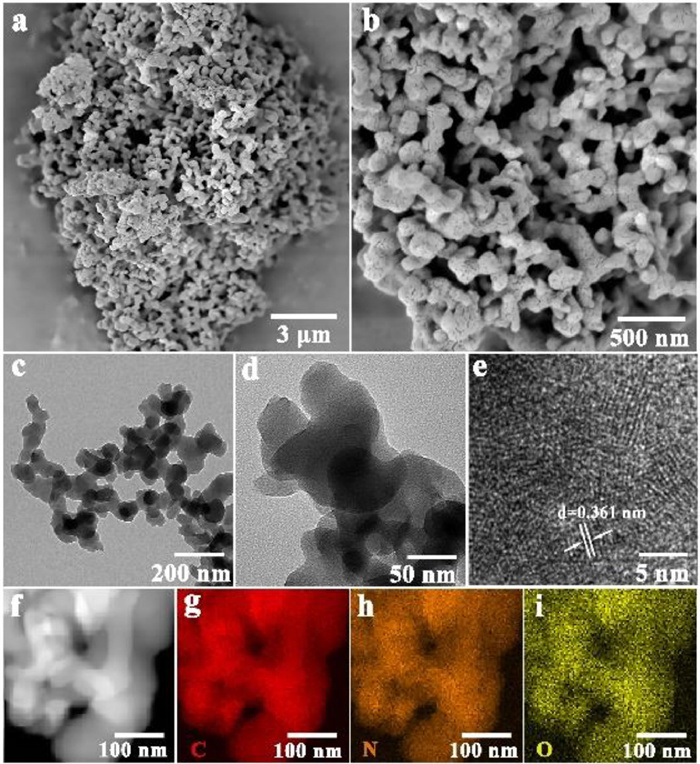
The morphology and detailed nanostructure of the PI-COF were investigated by scanning electron microscopy (SEM), transmission electron microscopy (TEM) and high-resolution transmission electron microscopy (HR-TEM), respectively. As shown in Figs. 2a and b, the synthesized PI-COF material had a uniform and regular morphology, consisting of small nanoparticles with obvious pores on the surface. Transmission electron microscopy further confirmed that PI-COF was composed of nanoparticles with a size of about 40–50 nm (Figs. 2c and d), which were closely connected to each other. High-resolution transmission electron microscopy (Fig. 2e) images showed that PI-COF has weak lattice fringes, indicating a certain degree of crystallinity. Additionally, element mapping images of carbon, nitrogen, and oxygen in PI-COF indicated uniform distribution of these elements. Additionally, the element mapping images of PI-COF clearly showed that the C, N, and O elements were evenly distributed in Figs. 2f–i.
The successful imidization of TAPP and EDTAD was demonstrated by powder X-ray diffraction (PXRD) and Fourier-transform infrared spectroscopy (FT-IR). As shown in Fig. 3a, the PXRD pattern of PI-COF (red curve) possesses intense diffraction peaks at 2θ = 2.62° and 4.13°, which are assigned to the (100) and (110) facets, respectively, indicating the good crystallinity of PI-COF. A smaller peak around at 2θ = 20° was also ascribed to the π-π stack generated by the (001) plane, matching with the AA stacking model with d-spacing of 3.47 Å (Fig. 1b). We simulated the two cases of eclipsed (AA) and staggered (AB) stacking models (Figs. S1 and S6 in Supporting information) and calculated their fitted values (Fig. 3a, blue and purple traces, respectively). After comparing with the experimental powder X-ray diffraction pattern for PI-COF at room temperature (Fig. 3, black trace), the AA stacking model was deemed optimal, and Pawley refinement accordingly yielded the following unit cell parameters: a = 55.66 Å, b = 55.23 Å, c = 17.43 Å, α = β = 90°, γ = 89.5°. It is worth noting that crystallinity is one of the key factors that can affect the electrochemical and thermal properties of polymer electrode materials [31]. The FT-IR spectrum of PI-COF displayed a new absorption peak at 1402 cm−1, which was attributed to the stretching mode of imide C-N-C (Fig. 3b) [32]. The disappearance of the stretching peaks of the amino groups (around 3329 cm−1) and anhydride C=O groups (around 1765 cm−1) indicates the formation of imide from the amino groups and anhydride units. In addition, the characteristic band at 1650 cm−1 in PI-COF is attributed to the asymmetric vibrations of the C=O group. The signal of the carbonyl groups in PI-COF exhibits a downward shift in wavenumbers compared to those of the carbonyl groups in the reactant dianhydride, indicating the formation of the polyimide backbone [33].
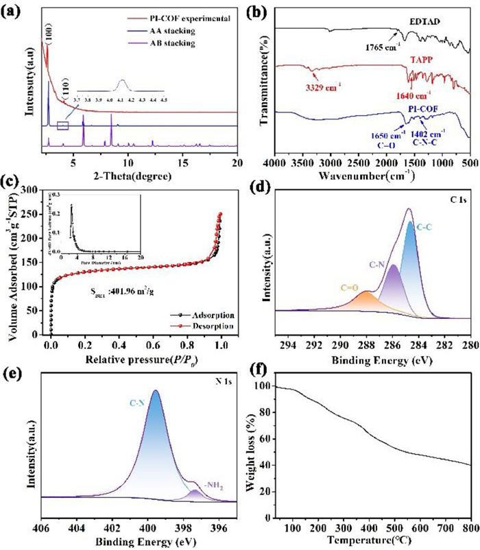
The porosity of PI-COF is measured using the nitrogen absorption isotherms and corresponding pores at liquid nitrogen temperature (77 K). As shown in Fig. 3c, the specific surface area of the PI-COF is up to 401.96 m2/g. In addition, the pore size distribution based on non-local density functional theory (NLDFT) leads to the main pore size distribution concentrated at ~2.55 nm (Fig. 3c inset), which is close to the theoretical value (3 nm, Fig. S1) calculated by the Forcite module of Materials Studio. In this regard, we can conclude that the as-prepared PI-COF is a 2D material with high porosity and a large specific surface area, which is beneficial for transferring Li-ions during the charge−discharge process [27].
To analyze the chemical composition of samples, X-ray photoelectron spectroscopy (XPS) was further used to characterize PI-COF. The XPS survey spectra of PI-COF are shown in Fig. S2 (Supporting information), confirming the co-existence of carbon, nitrogen and oxygen elements in PI-COF. The C 1s (Fig. 3d) spectrum for PI-COF contains three peaks at ~288.1, ~285.9, and ~284.6 eV, corresponding to C=O, C-N and C=C. In the N 1s spectrum (Fig. 3e), the N 1s region analyses of PI-COF show the presence of two peaks at ~399.7 and ~397.5 eV. The peak at about 399.7 eV (C-N) can be ascribed to the pyrrole nitrogen atoms. It is well known that pyrrole nitrogen can create defects that provide active sites for Li-ion storage, and a porphyrin molecule can contain up to four pyrrole nitrogen molecules to enhance electrochemically active sites [34,35]. The peak at 397.5 eV belongs to the -NH2 at the end of the TAPP monomer. The XPS spectrum of O 1s (Fig. S3 in Supporting information) for PI-COF shows the presence of C=O. In addition, the thermogravimetric analysis (TGA, Fig. 3f) indicates the thermal stability of PI-COF can reach 350 ℃, which conforms to the rigid characteristics of PI-COF materials [36].
The PI-COF was used as the anode for LIBs and its electrochemical performance was evaluated in a potential window ranging from 0.01 V to 3.0 V. Fig. 4a shows the first three cyclic voltammogram (CV) of the PI-COF electrode at a scanning speed of 0.2 mV/s. The CV curve of the first cycle was quite different from the subsequent CV curve, especially in the discharge half-cycle where a strong reduction peak at 0.66 V can be observed, which is related to the formation of a solid electrolyte interface (SEI) layer and an irreversible reaction of Li with the functional groups on the surface of active materials [30,37]. The cathodic peak, which appeared at 0.20 V (vs. Li+/Li), corresponds to the reversible oxidation of the active group in PI-COF [38]. In the first cycle of the charging curve, two oxidation peaks located at 0.65 V and 1.29 V, which are related to the delithiation process. Compared to the first cycle, the peak current and the integral area of the second and third cycles were significantly decreased, indicating that an irreversible reaction and capacity loss during cycling. A reduction peak at around 0.87 V was observed in the subsequent cycles, which may indicate the activation of the material after the first cycle. In the following second and third potential scans, the redox peak gradually remained stable, suggesting highly reversible reactions and excellent cycling stability of COF-based LIBs.
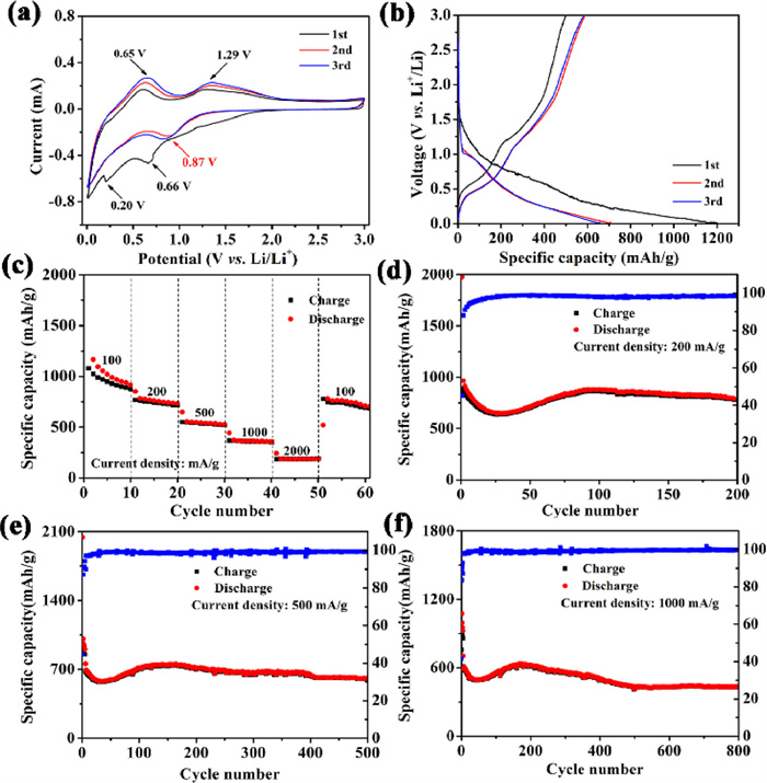
Fig. 4b shows the initial three discharge-charge voltage (0.01–3.0 V) distributions of PI-COF electrodes that were studied in the range of voltage 0.01–3.0 V and at a current density of 100 mA/g. In the test, the PI-COF electrode delivered the initial discharge capacity and charge capacity of 1737.1 mAh/g and 858.4 mAh/g, respectively, corresponding to an initial coulombic efficiency of 49.42%. The result may be caused by the irreversible reaction, including the formation of SEI layers and interfacial lithium storage [31,39-41]. The stable SEI film will be in favor of good thermal stability as anode materials for LIBs [42]. In the subsequent cycles, the discharge and charge profiles almost overlap, suggesting that the PI-COF anode has excellent cycling stability performance. From the second cycle, the charge and discharge capacities are up to 1023.3 and 1166.4 mAh/g, which the coulombic efficiencies of PI-COF electrodes are over 87.73%. Until the third cycle, the charge and discharge capacity of the PI-COF electrode was 989.6 and 1095.7 mAh/g, respectively. The coulombic efficiency of 95.3% indicates the stable formation of the SEI layer and the efficient transport of ions and electrons in the anode material. The Coulombic efficiency remains consistently above 99% in subsequent cycles at 0.2, 0.5, and 1 A/g current densities. These results demonstrate the occurrence of stable and reversible electrochemical reactions.
To understand the electrochemical performance of the prepared PI-COF electrode, its rate performance was further studied. Fig. 4c shows the rate capabilities of the PI-COF electrode when the current density is set to 100, 200, 500, 1000, and 2000 mA/g. The specific capacity of the PI-COF electrode is 871, 720, 520, 353, and 188 mAh/g, respectively, indicating excellent high-power performance. Under different current densities, the PI-COF electrode still exhibits persistent and stable rate performance. Additionally, it is worth noting that when the current density finally returns to 100 mA/g, the discharge capacity can return to 778.9 mAh/g, suggesting highly structural stability under high current densities. The results show excellent rate performance of the COF electrode in the lithium battery.
The long-term cycling performance of the PI-COF electrode at a current density of 200 mA/g is shown in Fig. 4d. After a small capacity decrease in the first 24th cycles, the obvious capacity increase can be observed for the PI-COF electrode from the 24th to 73th cycle due to the better electrolyte infusion and improved Li+ diffusion kinetics during repetitive cycling. The initial discharge capacity and charge capacity of the PI-COF electrode are 800 mAh/g after 200 cycles. Additionally, we also tested the cycling performance of the PI-COF electrode at 500 mA/g is shown in Fig. 4e. The specific discharge capacity of the PI-COF electrode remains at 610 mAh/g after 500 cycles. It can be clearly seen that the PI-COF electrode exhibits good cycling stability during the discharge/charge processes. The excellent cycling stability of PI-COF may be attributed to the stable conjugated bonds formed by cross-linked acyl-substituted conjugated molecules and the flexibility provided by long-chain EDTAD molecules.
The PI-COF electrode exhibits excellent long-life cycling performance at high current density. From Fig. 4f, the discharge capacity of the PI-COF electrode gradually increased as the cycle progressed, reaching a maximum value of 615.4 mAh/g at about the 200th cycle, which may be attributed to the activation process of the electrode [43]. It can be observed that a high reversible capacity of 450 mAh/g is still maintained after 800 cycles at 1000 mA/g for the PI-COF electrode, respectively. This excellent performance may be attributed to the large specific surface area and porous structure of PI-COF materials, as well as abundant redox active sites, which are conducive to the intercalation/deintercalation of Li+ ions, thus they exhibit excellent cycling stability and slow capacity fading, and the Coulombic efficiency exceeds 99%. Finally, the electrochemical behavior of the PI-COF material in our study has been compared with other COF anodes, as shown in Table 1. The PI-COF electrode exhibits excellent Li-ion storage performance with high capacity and good cycling stability.
Fig. S4 (Supporting information) shows the electrochemical impedance spectroscopy (EIS) of the PI-COF electrode before cycling over the frequency ranges of 0.01–100 MHz. Fig. S4 demonstrates the Nyquist plot of the PI-COF electrode, which comprises an imperfect semicircle in the moderate frequency area and an inclined line in the low frequency. The semicircle in the moderate frequency area can be attributed to the interfacial charge transfer resistance region. The low frequency straight line corresponds to the Warburg impedance (Zw), regarding the Li+ diffusion ability in electrodes [46,47]. It can be seen that the resistance of the PI-COF electrode is relatively small, suggesting a faster transfer rate of charges and higher transport kinetics of Li+. As shown in Fig. S4, the charge transfer process of PI-COF electrode is improved after 50 cycles, which may be attributed to the electrochemical activation process [48].
To evaluate the volume change of the PI-COF electrode material before and after cycling, we measured the thickness of the electrode sheet cross-section using SEM (Fig. S5 in Supporting information). The thickness of the electrode has slightly increased relative to that before the test, but there is no significant difference in the surface morphology of the electrode. By calculation, the expansion rate of the electrode sheet is only 124.8% (Table S1 in Supporting information), which is considered excellent among similar electrode materials. The lower expansion rate of the PI-COF electrode may be due to its unique structure of rigid-flexible combination formed by porphyrin and acid anhydride molecules, as well as the larger interlayer distance of COF.
In summary, a novel acyl-conjugated COF was synthesized by the imine reaction between EDTAD and TAPP, and was used as anode materials for LIBs. The PI-COF electrodes delivers a reversible specific capacity of 800 mAh/g after 200 cycles at a current density of 200 mA/g. Even at a higher current density of 1000 mA/g, the electrode maintained a reversible specific capacity of 450 mAh/g after 800 cycles, indicating excellent long-term cyclic stability. These outstanding electrochemical properties of PI-COF anode materials are mainly attributed to their abundant active sites, large specific surface area, and unique conjugated structure combining rigidity and flexibility. These characteristics are advantageous for achieving high specific capacity output, as well as improving the insertion and extraction rates of both charge carriers and lithium ions.
The authors declare that they have no known competing financial interests or personal relationships that could have appeared to influence the work reported in this paper.
This work was supported by National Natural Science Foundation of China for Youths (Nos. 21701059, 22205084, 51902140), Natural Science Foundation of Jiangsu Province for Youths (No. BK20170571). The authors also appreciate the financial support by Shandong Key Laboratory of Biochemical Analysis (No. SKLBA2103).
Supplementary material associated with this article can be found, in the online version, at doi:
X.T. Wang, Y. Yang, J.Z. Guo, et al., J. Mater. Sci. Technol. 102 (2022) 72–79. doi: 10.1016/j.jmst.2021.05.074
F. Xu, S. Yang, X. Chen, et al., Chem. Sci. 10 (2019) 6001–6006. doi: 10.1039/c8sc04518f
X. Peng, C. Xiong, Y. Lin, C. Zhao, T. Zhao, SmartMat 2 (2021) 579–590. doi: 10.1002/smm2.1061
H. Zhu, S. Dong, J. Xiong, et al., J. Colloid Interface Sci. 641 (2023) 942–949. doi: 10.1016/j.jcis.2023.03.083
M. Yang, Q. Ning, C. Fan, X. Wu, Chin. Chem. Lett. 32 (2021) 895–899. doi: 10.1016/j.cclet.2020.07.014
Q. Zhao, J. Wang, Y. Lu, et al., Angew. Chem. Int. Ed. 55 (2016) 12528–12532. doi: 10.1002/anie.201607194
H. Chen, M. Armand, G. Demailly, et al., ChemSusChem 1 (2008) 348–355. doi: 10.1002/cssc.200700161
F.B. Chen, B.R. Wu, Y.K. Xiong, et al., Int. J. Miner. Metall. Mater. 22 (2015) 203–209. doi: 10.1007/s12613-015-1062-6
Z. Song, Y. Qian, M.L. Gordin, et al., Angew. Chem. Int. Ed. 54 (2015) 13947–13951. doi: 10.1002/anie.201506673
W. Deng, J. Qian, Y. Cao, X. Ai, H. Yang, Small 12 (2016) 583–587. doi: 10.1002/smll.201502278
X. Wang, X. Tang, P. Zhang, et al., J. Phys. Chem. Lett. 12 (2021) 12055–12061. doi: 10.1021/acs.jpclett.1c03734
Y. Liang, Z. Tao, J. Chen, Adv. Energy Mater. 2 (2012) 742–769. doi: 10.1002/aenm.201100795
O.Y. Posudievsky, O.A. Kozarenko, V.S. Dyadyun, V.G. Koshechko, V.D. Pokhodenko, Synth. Met. 162 (2012) 2206–2211. doi: 10.1016/j.synthmet.2012.10.019
A. Wild, M. Strumpf, B. Häupler, M.D. Hager, U.S. Schubert, Adv. Energy Mater. 7 (2017) 1601415. doi: 10.1002/aenm.201601415
C. Zhang, Y. He, P. Mu, et al., Adv. Funct. Mater. 28 (2018) 1705432. doi: 10.1002/adfm.201705432
S. Haldar, K. Roy, R. Kushwaha, S. Ogale, R. Vaidhyanathan, Adv. Energy Mater. 9 (2019) 1902428. doi: 10.1002/aenm.201902428
Y. Tong, Z. Sun, J. Wang, W. Huang, Q. Zhang, SmartMat 3 (2022) 685–694. doi: 10.1002/smm2.1115
H. Chen, Y. Zhang, C. Xu, et al., Chem. Eur. J. 25 (2019) 15472–15476. doi: 10.1002/chem.201903733
J. Sun, R. Tian, Y. Man, Y. Fei, X. Zhou, Chin. Chem. Lett. 34 (2023) 108233. doi: 10.1016/j.cclet.2023.108233
Y. Han, Z. Liu, F. Zheng, et al., J. Alloys Compd. 881 (2021) 160531. doi: 10.1016/j.jallcom.2021.160531
L. Kong, C. Tang, H.J. Peng, J.Q. Huang, Q. Zhang, SmartMat 1 (2020), doi: 10.1002/smm2.1007.
X. Yang, C. Lin, D. Han, et al., J. Mater. Chem. A 10 (2022) 3989–3995. doi: 10.1039/d1ta09433e
K. Jeong, S. Park, G.Y. Jung, et al., J. Am. Chem. Soc. 141 (2019) 5880–5885. doi: 10.1021/jacs.9b00543
Z. Liu, F. Zheng, W. Xiong, et al., SmartMat 2 (2021) 488–518. doi: 10.1002/smm2.1064
L. Chen, M. Huang, B. Chen, et al., Chin. Chem. Lett. 33 (2022) 2867–2882. doi: 10.1016/j.cclet.2021.10.060
H. Yang, S. Zhang, L. Han, et al., ACS Appl. Mater. Interfaces 8 (2016) 5366–5375. doi: 10.1021/acsami.5b12370
G. Wang, N. Chandrasekhar, B.P. Biswal, et al., Adv. Mater. 31 (2019) 1901478. doi: 10.1002/adma.201901478
X. Zhao, P. Pachfule, S. Li, et al., J. Am. Chem. Soc. 141 (2019) 6623–6630. doi: 10.1021/jacs.9b01226
B.J. Smith, A.C. Overholts, N. Hwang, W.R. Dichtel, Chem. Commun. 52 (2016) 3690–3693. doi: 10.1039/C5CC10221A
Z. Lei, Q. Yang, Y. Xu, et al., Nat. Commun. 9 (2018) 576. doi: 10.1038/s41467-018-02889-7
J. Wu, X. Rui, C. Wang, et al., Adv. Energy Mater. 5 (2015) 1402189. doi: 10.1002/aenm.201402189
Q. Fang, J. Wang, S. Gu, et al., J. Am. Chem. Soc. 137 (2015) 8352–8355. doi: 10.1021/jacs.5b04147
D. Tian, H.Z. Zhang, D.S. Zhang, et al., RSC Adv. 4 (2014) 7506–7510. doi: 10.1039/c3ra45563g
B. Li, F. Dai, Q. Xiao, et al., Energy Environ. Sci. 9 (2016) 102–106. doi: 10.1039/C5EE03149D
M. Yang, Z. Zhou, Adv. Sci. 4 (2017) 1600408. doi: 10.1002/advs.201600408
H. Liu, H. Guo, B. Liu, et al., Adv. Funct. Mater. 28 (2018) 1707480. doi: 10.1002/adfm.201707480
Z.Q. Lin, J. Xie, B.W. Zhang, et al., Nano Energy 41 (2017) 117–127. doi: 10.1016/j.nanoen.2017.08.038
G. Zhao, Y. Zhang, Z. Gao, et al., ACS Energy Lett. 5 (2020) 1022–1031. doi: 10.1021/acsenergylett.0c00069
D.P. Dubal, K. Jayaramulu, R. Zboril, R.A. Fischer, P. Gomez-Romero, J. Mater. Chem. A 6 (2018) 6096–6106. doi: 10.1039/c8ta00549d
H. Jiang, S. Zhao, X. Ma, S. Liu, Q. Shen, J. Power Sources 426 (2019) 23–32. doi: 10.1016/j.jpowsour.2019.04.020
C. Li, T. Chen, W. Xu, et al., J. Mater. Chem. A 3 (2015) 5585–5591. doi: 10.1039/C4TA06914E
K. Edström, A.M. Andersson, A. Bishop, et al., J. Power Sources 97-98 (2001) 87–91. doi: 10.1016/S0378-7753(01)00593-6
Y. Dong, R. Ma, M. Hu, et al., PCCP 15 (2013) 7174–7181. doi: 10.1039/c3cp50588j
L. Bai, Q. Gao, Y. Zhao, J. Mater. Chem. A 4 (2016) 14106–14110. doi: 10.1039/C6TA06449C
S. Feng, H. Xu, C. Zhang, et al., Chem. Commun. 53 (2017) 11334–11337. doi: 10.1039/C7CC07024A
C. Zhang, W. Hu, H. Jiang, et al., Electrochim. Acta 246 (2017) 528–535. doi: 10.1016/j.electacta.2017.06.059
Q. Li, Q. Jiao, H. Li, et al., J. Alloys Compd. 845 (2020) 156183. doi: 10.1016/j.jallcom.2020.156183
M.S. Kim, M. Lee, M.J. Kim, et al., J. Mater. Chem. A 8 (2020) 17790–17799. doi: 10.1039/d0ta06206e

Figure 1 (a) Schematic representation of the synthesis processes of PI-COF. (b) Stacking distance between the two adjacent layers (O, red; N, blue; C, gray).

Figure 2 (a, b) SEM images of PI-COF. (c, d) TEM images of PI-COF. (e) High magnification TEM image of the PI-COF. (f-i) Elemental mapping images of C, O, and N.

Figure 3 (a) XRD pattern of PI-COF. (b) FT-IR spectrum of EDTAD, TAPP and PI-COF. (c) Nitrogen adsorption-desorption isotherms (77 K) with pore size distribution (inset). (d) High-resolution XPS spectra of C 1s of PI-COF. (e) High-resolution XPS spectra of N 1s of PI-COF. (f) Thermogravimetric analysis of PI-COF under N2 flow with a heating rate of 10 K/min.

Figure 4 Electrochemical performance of samples for LIBs: (a) CV curves of the PI-COF electrode for three cycles at a scan rate of 0.2 mV/s in voltage range of 0.01–3.0 V. (b) Discharge-charge profiles of the PI-COF electrode at 100 mA/g. (c) Cycling performance (0.01–3.0 V, 200 mA/g) of the PI-COF electrode. (d) Long cycle performance of the PI-COF electrode at a current density of 200 mA/g. (e) Long cycle performance of the PI-COF electrode at a current density of 500 mA/g. (f) Long cycle performance of the PI-COF electrode at a current density of 1000 mA/g.

 扫一扫看文章

扫一扫关注我们
 DownLoad:

 下载:
下载: