Citation:
Mingzhen Ding, Ruyu Shi, Jie Qu, Minman Tong. Construction of highly stable LiI/LiBr-based nanocomposite cathode via triple confinement mechanisms for lithium-halogen batteries[J]. Chinese Chemical Letters,
2023, 34(11): 108248.
doi:
10.1016/j.cclet.2023.108248
Construction of highly stable LiI/LiBr-based nanocomposite cathode via triple confinement mechanisms for lithium-halogen batteries
English
Construction of highly stable LiI/LiBr-based nanocomposite cathode via triple confinement mechanisms for lithium-halogen batteries
College of Chemistry and Chemical Engineering, Key Laboratory of Light Energy Conversion Materials of Hunan Province College, Hunan Normal University, Changsha 410081, China
b.
School of Chemistry and Materials Science, Jiangsu Normal University, Xuzhou 221116, China
Received Date:
24 November 2022 Accepted Date:
20 February 2023 Revised Date:
17 December 2022 Available Online:
15 November 2023
Abstract:
Lithium-halogen batteries (LHBs), including lithium iodide (Li-I2) and lithium bromide (Li-Br2) batteries, are receiving more attention for offering high energy density and excellent kinetic performance. However, LHBs commercialization is seriously hindered by the high solubility of halides, causing lower capacity and poor cyclability. This research covers the fabrication of a highly stable cathode of amorphous carbon coated CMK-3/LiI/LiBr nanocomposite for metal lithium batteries. The nanopores and coated layer can physically trap the dissolution of active materials. The amorphous carbon generated from polyacrylonitrile carries abundant nitrogen heteroatoms for the stable anchorage of halogens and halides via strong chemical adsorption. In addition, iodine can act as a complexing agent with bromine to reduce solvation energy. Consequently, the as-prepared CMK-3/LiI/LiBr/carbon (CIBP) nanocomposite cathode demonstrates an ultra-high reversible capacity of 407.4 mAh/g at the current density of 1.0 C performing up to 300 stable cycles.
Lithium-ion batteries (LIBs) have become the dominant power source for electric vehicles recently. However, the low energy density and poor rate performance of LIBs cause serious range anxiety, affecting the widespread promotion of electric vehicles [1–5]. Therefore, industrialists are seeking novel energy storage system with high energy density and excellent performance rates.
Due to their high energy density and excellent electrochemical kinetics, LHBs, which use lithium as anodes and iodine (I2) or bromine (Br2) as cathodes, stand out among all the given choices [6–18]. Particularly for Li-Br2 batteries, it can demonstrate a better energy density of 1273 Wh/kg and a potential of 4.12 V, which is much greater than commercial LIBs [13,18]. However, bromine and bromide are highly soluble in organic electrolytes, and during the discharge-charge process, they can diffuse to the Li-anode, causing serious shuttle effect, further leading to loss of active materials and severe Li corrosion. One of the effective ways to overcome the above problems is developing carbon materials to confine the bromide species within the porous structure. Wang et al. [17] fabricated the lithium bromide-conductive carbon black composite with LiBr embedded into the pores of conductive carbon. Such composite alleviated the shuttling effect of Br−/Br3− with a high initial charge capacity of 333.1 mAh/g and capacity retention at 89.5% after 100 cycles. Peterson et al. [18] used microporous carbonized metal-organic frameworks (MOFs) to trap bromine and polybromides. Higher LiBr loading might result from more monodisperse microporosity and nitrogen heteroatom doping, which is thought to improve capacity and capacity retention. An initial discharge capacity of 305 mAh/g was observed with a 88% capacity retention over 100 cycles. Even if the electrochemical performance is substantially improved, it is hard to entirely prevent the dissolution of active components using simply physical adsorption. The dissolved bromine or bromide could still build up and thus destroy the long-term cycling performance of the battery.
To address the above issues, we design a novel amorphous carbon coating CMK-3/LiI/LiBr nanocomposite (CIBP) and expect to effectively limit the dissolution of active materials via triple confinement mechanisms. As illustrated in Fig. 1a, firstly, the developed mesopores and amorphous carbon layer can physically trap the dissolution of iodine, iodide, bromine, or bromide. Secondly, the coating amorphous carbon layer with rich N-heteroatoms presents strong chemical interactions with halogens or halides, thus preventing the escaping of Br−/Br3− from the inner space. Thirdly, the self-limiting effect will happen during the charging process. By interacting with other halogens, LiI in this composite can effectively inhibit the dissolution of Br− or Br3− in addition to acting as active materials. Due to the triple confinement mechanisms, the as-prepared nanocomposite can demonstrate an ultra-high initial capacity of 463.4 mAh/g at the current density of 1 C (500 mA/g) and coulombic efficiency of 87.9%.
Figure 1
Figure 1.
(a) Schematic illustration of the triple confinement mechanisms of CIBP nanocomposite. (b) N2 adsorption-desorption isotherms of different nanocomposites and (c) their corresponding pore-size distributions. (d) FTIR spectrum of different nanocomposites. High-resolution XPS spectra of (e) C 1s and (f) Br 3d. (g) Calculated solvation energy of substances that may be present in the electrolyte during the charging process.
Initially, the nitrogen isothermal adsorption-desorption measurement was used to look into the porous structure. As shown in Fig. 1b, CMK-3 exhibits a typical type IV isotherm with H3 hysteresis loop at the relative pressure of P/P0 of around 0.5–0.7, suggesting the presence of mesopores, while a sharp increase at relatively low pressure (P/P0 < 0.1) indicates the presence of abundant micropores [19,20]. After LiI and LiBr loading, a significant decrease was observed in the adsorbed volume, indicating the dissolution of LiI and LiBr into the nanopores of CMK-3, especially after introducing a carbonized PAN coating layer. Such a filling can be more clearly illustrated by the decrease of pore size distribution (Fig. 1c) and surface area (Table S1 in Supporting information). The nanopores of CMK-3 can well restrict the diffusion of LiI and LiBr in the electrolyte. The existence of LiI and LiBr in the nanocomposite also can be confirmed by the XRD patterns (Fig. S1 in Supporting information). The entire datas were obtained by wrapping samples with Parafilm, and blank Parafilm was also tested for comparison. The sharp peaks at 4°, 22°, 24° and the broad peak around 15° are attributed to the Parafilm. The diffraction peak at 25.8° belongs to LiI, and the diffraction peaks at 22.3° and 31.8° are ascribed to LiBr. It should be noted that after mixing with PAN the peak of LiI at 26.2° for CIBP nanocomposite is red-shifted by 0.4°, which may be caused by the strong interaction between LiI and carbonized PAN [21,22].
The strong chemical interactions, even chemical bonds, between LiI, LiBr, and carbonized PAN can be further verified by the results of FTIR and XPS in Figs. 1d–f. As shown in Fig. 1d, the strong peak located at 3433 cm−1 is assigned to the stretching of hydrogen-bonded hydroxyl (O—H) moieties [23,24]. The peaks at 1150 and 1433 cm−1 contributed to the C—O bond [24] and C=N stretching [25], respectively. The presence of the C-I and C-Br halide groups is shown by the modest peaks at 520 cm−1 [26–28]. The overall XPS spectra (Fig. S2a in Supporting information), reveal that two distinct peaks of O 1s at 532.6 eV and C 1s at 285.6 eV are observed for CMK-3, while after introducing LiI, LiBr, and PAN into CMK-3, additional peaks appearing at 48.6 eV for Li 1s, 68.7 eV for Br 3d, 182.1 and 188.1 eV for Br 3p, 630.1 and 620.1 eV for I 3d and 400.1 eV for N 1s are observed. The high-resolution XPS of C 1s (Fig. 1e) for CIBP nanocomposite further revealed that C 1s can be fitted into C—C (284.8 eV), C=C (284.1 eV), O—C/C=O (289.2 eV), COOH groups (290.8 eV), C—N (288.4 eV), C-Br (286.3 eV) and C-I (285.2 eV) [29–32]. An obvious peak shift of the CIBP nanocomposite was observed compared with that CIB nanocomposite (Fig. 1f, Figs. S2b and c in Supporting information), indicating the strong chemical adsorption of carbonized PAN [33].
The interaction between various halogens cannot be disregarded in addition to physical and chemical adsorptions since each halogen has a varied solubility in solvents. To deeply understand the self-adsorption between different halogens in the cathode, density functional theory (DFT) computations were conducted (Fig. 1g and Fig. S3 in Supporting information). During the charging process, LiI is firstly reduced to generate I2, which can combine with Br− and Br3− and solvation energy can increase to −33.34 and −34.4 kcal/mol. Noting that the solvation free energy of Br3− and Br− is −39.29 and −48.05 kcal/mol, respectively, both of the I2…Br3− and I2…Br− complex can distinctly reduce the solvation of Br3− and Br− in the electrolyte, thus enhancing the cycling stability of the nanocomposite cathode.
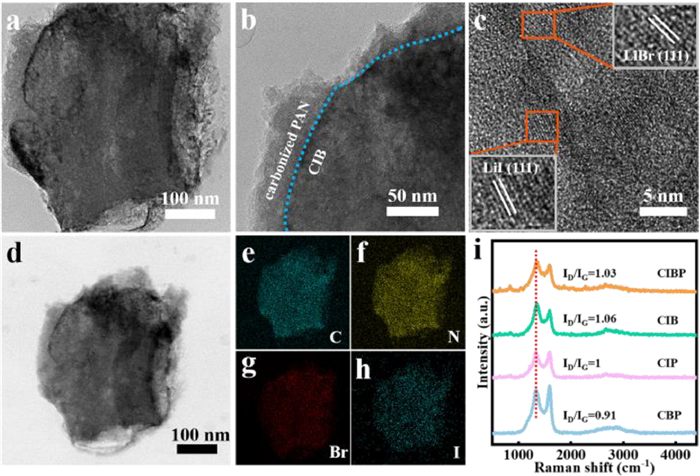
TEM and HRTEM are further performed to detect the structure of the CIBP nanocomposite. It can be seen from Fig. 2a that the regular structure of CMK-3 is well retained after the filling of LiI/LiBr and the covering of PAN. As shown in Fig. 2b, carbonized PAN is evenly covered on the surface of CMK-3, which can tightly enclose the LiI/LiBr in CMK-3. High-energy ball milling and high-temperature treatment of PAN produce a conductive amorphous coating layer, which is more conducive to the migration of lithium ions [34–36]. Two different lattice fringes are detected in Fig. 2c. An average lattice spacing of about 0.35 nm is corresponded to the (111) plane of LiI and the lattice spacing of about 0.32 nm belongs to the (111) plane of LiBr [17,37]. This result is consistent with the XRD analysis and further certify the existence of LiI/LiBr. The element mapping images shown in Figs. 2d–h confirm the uniform distributions of I and Br elements inside the whole composite. Raman spectra were further performed to reveal the different states after simultaneously introducing LiI and LiBr in the nanocomposite (Fig. 2i). The as-known D and G bands were observed to be 1330 and 1591 cm−1. The intensity ratios of ID/IG values for CIP and CBP nanocomposites are 1 and 0.91, respectively. However, the values for CIB and CIBP nanocomposites are increased to 1.06 and 1.03, respectively, corresponding to an increased number of defects and a more disordered structure [38,39]. Such results revealed that there is a synergistic effect between LiBr and LiI during the carbonization process of PAN.
Figure 2
Figure 2.
(a, b) TEM image, (c) HRTEM images and (d–h) the corresponding elemental mapping images of the CIBP nanocomposite. (i) Raman spectra of different nanocomposites.
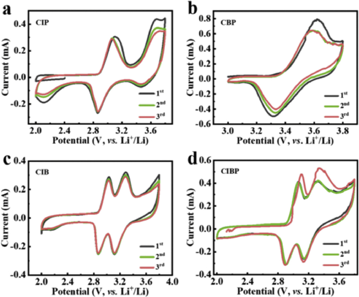
Cyclic voltammograms (CVs) are taken out to gain insight of the electrochemical reaction mechanism of the prepared nanomaterials. As shown in Fig. 3a, in the anodic scan of the CIP nanocomposite, LiI is oxidized to LiI3 at 3.1 V, and further to I2 at 3.7 V. The battery reaction is described by the following equations:
(1)
(2)
Figure 3
Figure 3.
CV curves of (a) CIP, (b) CBP, (c) CIB and (d) CIBP nanocomposites at the scan rate of 1 mV/s.
In the cathodic scan, I2 is reduced to LiI3 at 3.5 V, and further to LiI at 2.88 V [11,40–42].
The CV of CBP nanocomposite is listed in Fig. 3b. In the anodic scan, Br− is oxidized to Br3− at 3.62 V, which is reduced to Br− in the cathodic scan at 3.33 V [18,43]. However, an interesting phenomenon has been observed in case of the CIB nanocomposite, for which the redox peaks corresponding to Br− and Br3− greatly shift to lower potential. As shown in Figs. 3c and d, similar trends were seen for the CIBP nanocomposite in comparison to the CIB nanocomposite, indicating that the change was caused by interactions between I2 and Br3−/Br−, which was also predicted by computations.
Impedance measurements were conducted at an open circuit potential after standing for 6 h. As shown in Fig. S4 (Supporting information), Nyquist plots for CIP, CBP, CIB and CIBP nanocomposites include a semicircle in the high-frequency region and a straight line in the low-frequency region, which are related to the charge transfer process and the Warburg diffusion process, respectively [40]. However, the Nyquist plot for CIB nanocomposite without carbonized PAN consist of two semicircles in the high and medium frequency regions, which was presumably due to dissolved redox species [44]. Among all the samples, CIBP nanocomposite shows the lowest charge transfer resistance, indicating the best kinetic performance.
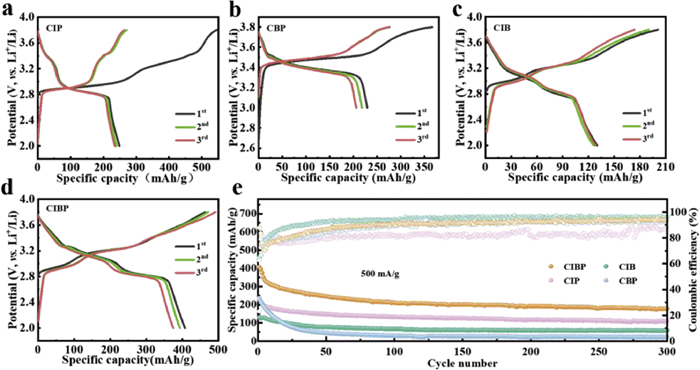
The initial three charge and discharge curves of the four nanocomposites are measured at the current density of 1 C in Figs. 4a–d. Clear charge/discharge platforms have appeared in all the batteries. Two pairs of plateaus were observed for CIBP, CIB, and CIP nanocomposites, consistent with the CV profiles. For CBP nanocomposite, the charge voltage plateaus of 3.5 V is ascribed to the formation of Br3−. During the discharge process, Br3− is reduced to Br− at around 3.4 V [17]. Notely, the voltage plateaus of both CIBP and CIB nanocomposites are lower than that of CBP nanocomposite, caused by the formation of I2Br3−/I2Br− ions, which can induce electrode polarization [45]. Besides, CIBP nanocomposite delivers an initial charge and discharge capacity of 463.4 and 407.4 mAh/g, respectively, much higher than the other three samples, accompanied by a high initial Coulombic efficiency of 87.9%, for which the CE values for CIP, CIB and CBP nanocomposites are only 23.4%, 64.8% and 62.5%, respectively.
Figure 4
Figure 4.
The initial three charge-discharge curves of (a) CIP, (b) CBP, (c) CIB and (d) CIBP nanocomposites. (e) Cycling performance of different nanocomposites at 1 C for 300 cycles.
The long-term cycling performance of the prepared nanocomposites is shown in Fig. 4e. After 300 cycles at 1 C, the discharge capacity of the CIBP nanocomposite was observed to be constant at about 177.7 mAh/g, significantly higher than those of CIP, CIB, and CBP nanocomposites (109.5, 58.4 and 23.3 mAh/g, respectively). Obviously, CMK-3, carbonized PAN, and I2 all play an important role to confine LiBr, as we all know single confinement is not enough, only if they combine, and incredible limitations can be inspired. Moreover, the Coulombic efficiencies for all the samples are above 85%, especially for CIBP, CBP and CIB nanocomposites, the values are over 93%. The above results indicate that CIBP nanocomposite exhibits high discharge capacity and good cycling performance. A comparison with similar researches is also shown in Table S2 (Supporting information). It is obvious that our work presents a relative higher charge/discharge capacity compared with other reported article. And a longer cycle performance is also presented, which is three times longer than other previous results.
Concluding, CIBP nanocomposite cathodes are prepared via a facile method, for which LiI and LiBr are filled in the nanopores of CMK-3 and then coated by the carbonized PAN layer. During the cycling, the dissolution of active materials is well inhibited by the nanopores and carbonized PAN via physical and chemical adsorption. Especially, the generated I2 during the charging process can act as the complexing agent to stabilize the Br3−/Br− and form iodine-bromide ions (I2Br3−/I2Br−) to further reduce the solvation energy of Br3−/Br−. The interactions between different halogens can be confirmed by the DFT calculations and CV curves. Accordingly, the as-prepared nanocomposite demonstrates a high initial capacity, Coulombic efficiency, good rate capability, and long cycle life. The creation of high-energy Li-halogen batteries is made possible by the design that uses mixing halides as a unique nanocomposite cathode.
Declaration of competing interest
The authors declare that they have no known competing financial interests or personal relationships that could have appeared to influence the work reported in this paper.
Acknowledgments
The authors acknowledge the financial support by the Research Foundation of Hunan Education Committee of China (No. 21B0067) and Natural National Science Foundation of China (No. 22278197).
Supplementary materials
Supplementary material associated with this article can be found, in the online version, at doi:10.1016/j.cclet.2023.108248.
[1]
J. Cui, T.G. Zhan, K.D. Zhang, et al., Chin. Chem. Lett. 28 (2017) 2171–2179. doi: 10.1016/j.cclet.2017.11.039
Figure 1
(a) Schematic illustration of the triple confinement mechanisms of CIBP nanocomposite. (b) N2 adsorption-desorption isotherms of different nanocomposites and (c) their corresponding pore-size distributions. (d) FTIR spectrum of different nanocomposites. High-resolution XPS spectra of (e) C 1s and (f) Br 3d. (g) Calculated solvation energy of substances that may be present in the electrolyte during the charging process.
Figure 2
(a, b) TEM image, (c) HRTEM images and (d–h) the corresponding elemental mapping images of the CIBP nanocomposite. (i) Raman spectra of different nanocomposites.
Figure 4
The initial three charge-discharge curves of (a) CIP, (b) CBP, (c) CIB and (d) CIBP nanocomposites. (e) Cycling performance of different nanocomposites at 1 C for 300 cycles.


 DownLoad:

 下载:
下载:


