School of Chemistry, Northeast Normal University, Changchun 130024, China
b.
Center for Lignocellulosic Chemistry and Biomaterials, College of Light Industry and Chemical Engineering, Dalian Polytechnic University, Dalian 116034, China
c.
State Key Laboratory of Advanced Electromagnetic Engineering and Technology, School of Electrical and Electronic Engineering, Huazhong University of Science and Technology, Wuhan 430074, China
Received Date:
08 December 2022 Accepted Date:
12 January 2023 Revised Date:
28 December 2022 Available Online:
15 September 2023
Abstract:
Li metal is considered an ideal anode material because of its high theoretical capacity and low electrode potential. However, the practical usage of Li metal as an anode is severely limited because of inevitable parasitic side reactions with electrolyte and dendrites formation. At present, single-component artificial solid electrolyte interphase cannot simultaneously meet the multiple functions of promoting ion conduction, guiding lithium ion deposition, inhibiting dendrite growth, and reducing interface side reactions. Therefore, multi-component design on Li metal surface is widely investigated to achieve long-term cycling. Herein, we report a Li2Ga-carbonate polymer interphase layer to solve volume changes, Li dendrites formation and side-reactions. As a result, the Li symmetric cell can be stabilized at 3.0 mA/cm2 in carbonate electrolyte with limited volume of 20 µL. Coupled with 13.6 mg/cm2 (loading of 2 mAh/cm2) LiFePO4 cathode, discharge capacity retains at 90% for over 150 cycles under limited electrolyte conditions. With such an alloy-polymer interphase layer, higher energy density Li metal batteries become prominent in the near future.
Anode materials with higher specific capacity are the most challenge to the next-generation battery systems [1-4]. Among them, Li metal is considered as the ideal material for anodes because of the higher energy density of 3860 mAh/g and the lower potential of −3.04 V (vs. H2/H+) [5-7]. However, organic electrolytes would be severely reduced by Li metal, resulting in formation of dendrites. Dendrites are lost from Li anode and become dead lithium during lithium stripping, causing low Columbic efficiency (CE). Practical application of lithium metal battery (LMB) is still an impossible at current stage [8,9]. Therefore, two strategies have been proposed including construct conductive skeletons for Li deposition and an artificial interface protective layer. A hierarchical structure host/framework composed of carbon-based and metallic materials has a large surface area and exhibits good conductivity, which cannot only reduce the local current density, but also relieve lithium dendrites and accommodate volume change of Li [10-18]. However, due to its increased inert weight and volume, the use of additional materials significantly reduces the energy density. Additionally, large specific areas consume more electrolytes and active Li, often causing safety hazards [19].
In order to prevent inhomogeneous Li plating/stripping of metal anodes, a protection layer is crucial [20]. Thereby, Li metal maintains at its specific capacity, but also decrease reactions between it and its electrolyte. The intrinsic solid electrolyte interphase (SEI) layer is usually mechanical instability during Li deposition/dissolution processes [21]. The properties of SEI formation can be modulated by optimizing electrolyte compositions such as solvents, Li salts, and fluorinated compounds [22-25]. Besides, artificial SEI layers can protect the Li metal [26], including Li+ conductor [27,28], carbon nanofibers [29,30], metal oxides [31,32] and Li alloy [33-37]. However, artificial SEI normally cannot heal itself, leading to gradual deterioration of its performance over time. Recently, liquid metals based SEI (self-healing [38], damage repairing [39]) shows great potential for Li metal anode modification. Among them, Ga-based liquid metals are more attractive due to their nontoxic, chemical stability, and strong bonding interactions [40-43]. Self-healing ability of metal Ga in liquid electrolyte is limited, and the performance of self-healing electrodes remains unsatisfactory. Especially, other metallic elements are added to adjust surface tension and melting point. Wang et al. reveal that adopting soft substrates to alleviate the residual stress can suppress Li dendrites [44]. In addition, commercial electrolyte without initiator forming a flexible membrane on Li electrode with simple process is important to achieve improved electrochemical properties.
In this work, nanoparticle dispersion of gallium (Ga) was applied to Li foil by dropping it on the surface, and alloy layer (Li-Ga) was formed. Taking advantage of the Ga catalytic properties, carbonate polymer film was formed on the surface of Li-Ga alloy. The composite artificial interphase suppress the dendrites of Li and promotes uniform Li nucleation and deposition through the synergetic function of alloy and polymer. As a result, artificial in-situ formed polycarbonate (AIFP) Li-Ga symmetric cells show excellent cycling stability for over 1300 h and hysteresis of only 3 mV at 1 mA/cm2. Besides, by matching AIFP Li-Ga with LiFePO4 (LFP), LiNi0.8Co0.1Mn0.1O2 (NCM811) and LiNiO.6Co0.2Mn0.2O2 (NCM622) cathodes, the full cells achieve greater cycling stability, higher discharge capabilities and stable CE than bare Li anodes. A long-term at 0.5 C revealed that the AIFP Li-Ga||LFP cell delivers a high discharge capacity of 136.77 mAh/g after 150 cycles. This work presents a simple and effective method for the development of Li metal anodes with high performance.
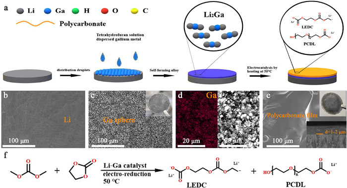
The proposed mechanism of alloy and in-situ formed polycarbonate multicomponent SEI was shown in Fig. 1a. Ga nanoparticles dispersed in tetrahydrofuran (THF) liquid (Fig. S1 in Supporting information), and was dropped onto the surface of Li foil (Fig. 1b). Li alloy was in the shape of sphere of a diameter of 2–10 µm (Fig. 1c). Alloy layers typically measure between 1 and 2 µm thick (Fig. S2 in Supporting information). Then, an alloy layer was formed, as seen from the darkness of Li metal surface (Fig. S3 in Supporting information). The alloy reaction was uniform, as evidenced by the energy dispersive spectroscopy (EDS) mapping of Ga element and backscattering electron image (Fig. 1d). Dense and darker film was formed on the surface of Li-Ga alloy after the electrochemical polymerization process at 50 ℃ (Fig. 1e). Under the same conditions, no film is found on the surface when bare lithium used (Fig. S4 in Supporting information). Polycarbonate film was formed through carbonate solvent ring-opening reaction, which is catalyzed by Li-Ga alloy (Fig. 1f).
Figure 1
Figure 1.
The mechanism of alloying and in-situ multicomponent SEI formation. (a) Proposed mechanism of SEI formation on Li anode. (b) Bare Li. (c) Ga dispersion on the surface of Li metal. (d) Li-Ga alloy on Li metal. (e) Li-Ga/polymer coated Li metal. (f) The proposed dimethyl carbonate polymerization reactions of EC via the ring-opening reaction. Lithium ethylene dicarbonate (LEDC), polycarbonate diols (PCDL).
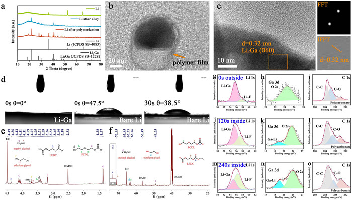
To testify our assumption, X-ray diffraction (XRD) patterns of Li metal, Li-metal after alloy reaction and Li metal after polymerization reaction were recorded (Fig. 2a). Li2Ga diffraction peaks replaced the pristine Li peaks after the first reaction, which proved the formation of Li-Ga alloy on the surface. A small amount of unreacted Li peak was observed in the sample after polymerization process, which was due to the consumption of partial Ga. The multicomponent SEI structure was further analyzed using transmission electron microscopy (TEM). From the TEM image, a Li-Ga nanoparticle of 100 nm length and 120 nm width was covered by a dense film as shown in Fig. 2b. The nanoparticle was enlarged with higher magnification, and the lattice fringes in Fig. 2c was assigned to Li2Ga with a spacing of 0.32 nm, corresponding to the Li2Ga (060) facet. To understand the affinity between electrolyte and anode, the contact angle tests were conducted (Fig. 2d). For Li-Ga anode, the 0° at 0 s indicates that the electrolyte was fully wetted. The bare Li shows bad electrolyte wetting phenomenon. Even after 30 s, the contact angle was still as high as 38.5°. Li-Ga had better electrolyte wetting, which will facilitate the mass transport during reaction.
Figure 2
Figure 2.
(a) X-ray diffraction patterns of different Li metal. (b, c) TEM image of SEI layer. (d) Contact angles of anode. (e, f) 1H and 13C NMR spectra of polymer film on anode. (g-o) XPS of Li anode.
To understand the polymer film composition, the 13C and 1H NMR spectra was presented in Figs. 2e and f. Apart from the pristine peaks assigned to dimethyl carbonate (DMC, 3.72 ppm) and ethylene carbonate (EC, 4.50 ppm), several additional peaks were observed in the 1H spectroscopy between 1 ppm and 4.5 ppm (Fig. 2e) that were not present in the raw electrolyte (Fig. S5 in Supporting information). The results confirmed that the main products were Lithium ethylene di-carbonate (LEDC), 2-propoxyethyl hydrogen carbonate (PCDL), ethylene glycol and methanol. In the cycled electrolyte samples, these included an intense singlet at 4.36 (h proton), 3.69 (f proton), 3.66 (a proton), 3.52 (b proton), 3.45 (d proton) ppm, 3.18 (g proton) ppm that appears after the cycle and several multiple peaks at 4.12–4.05 (c proton), 1.38–1.37 (e proton) ppm. The h proton at 4.36 ppm was assigned to LEDC, the labeled f proton and g proton were assigned to ethylene glycol, the singlet a (ppm) and e (ppm) protons were assigned to methanol. The single d (ppm) proton, b (ppm) proton and c (ppm) proton analysis were the characteristic peak of PCDL. Moreover, as further support for the structure conjecture, 13C NMR spectra (Fig. 2f and Fig. S6 in Supporting information) was also obtained, and these results were consistent with NMR spectrum results obtained for 1H NMR. The molecular weight content of the carbonate polymer was characterized by Mass Spectrometry, showing different molecular weight (Mw = 344, 681 and 1019 g/mol), suggesting the carbonate polymer was an oligomer (Fig. S7 in Supporting information). Considering the mechanism of anionic ring-opening polymerization of caprolactone initiated by active alkali metals (such as K and Na) [45], this ring-opening polymerization is also expected to follow the anionic polymerization mechanism initiated by Li-Ga. Due to LEDC's poor stability, the carbonate polymer with excellent flexibility properties was formed after blending with PCDL. The AIFP skeleton with a linear chain structure rich in ether bonds shows fast lithium ions (Li+) transportation, which is proved in polymers with similar structures, such as polyethylene oxide [46]. Different polymerization pathways were proposed to synthesize EC and DMC (Fig. S8 in Supporting information), calculation result indicates that the polymerization process of electrolyte is spontaneously.
To identify the detailed chemical composition of Li metal surface, XPS analysis with different etching time were recorded (Figs. 2g-o). The XPS results proved that the Li2Ga-carbonate polymer interphase layer was divided into outer carbonate polymer at the top surface and inner Li2Ga alloy close to Li metal. Li2Ga alloy layer was composed of Li2Ga alloy (Figs. 2g, j and m), and there was lithium fluoride at the bottom of the metal layer, which was the early product of the decomposition of lithium hexa-fluorophosphate in the electrolyte. Outer carbonate polymer was evidenced by carbonate polymer groups the C-C (284.7 eV), C-O (286.8 eV), and polycarbonate (290.0 eV) in C 1s high resolution XPS [47]. After contacted with Li2Ga alloy, the polycarbonate content in the inner layer increases significantly according to C 1s XPS due to the decomposition of the electrolyte. (Figs. 2i, l and o). Besides, no elemental gallium was detected in the surface layer, and Ga-Li (19.6 eV) was detected with increasing etching depth, indicating that the polycarbonate was covered with the surface of the metal layer from the Ga 3d spectrum (Figs. 2h, k and n). Therefore, on top of the Li metal surface, we constructed a carbonate polymer layer based on Li2Ga alloy, which may maintains high stability over extended cycling.
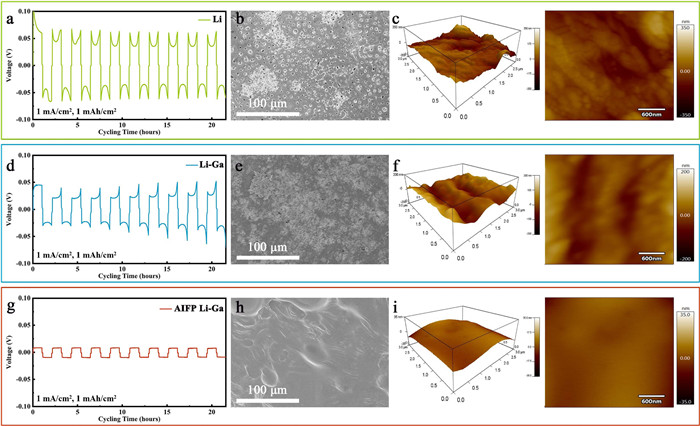
To understand the lithium plating behavior of protected Li metal, a symmetrical battery was assembled under 1 mA/cm2 and 1 mAh/cm2 As presented Fig. 3, AIFP Li-Ga modified Li symmetrical cell showed smooth voltage plateaus and maintained a stable overpotential of 7 mV until 10 cycles (Fig. 3g), implying that Li dissolution was uniform. At first, the abrupt voltage increased to 100 mV, corresponding to the big resistance of the initial stripping from the uncycled Li. At the end of the initial stripping, pits can be observed, implying that Li dissolution was not uniform. The bare lithium exhibits large voltage fluctuations, mainly arcing voltage profiles, with an overpotential of more than 60 mV in 10 cycles (Fig. 3a). For negative electrode protected by Li-Ga alloy, the initial stripping process was optimized, and lithium was easier to be plated. But the voltage fluctuation increased gradually, and the arc voltage curve was still dominant. This was ascribing to the increase in the migration resistance of Li ions at an electrode surface. The polarization voltage reached 50 mV after 10 cycles (Fig. 3d).
Figure 3
Figure 3.
Galvanostatic cycling of the symmetric Li||Li, Li-Ga||Li-Ga and Li-Ga AIFP||AIFP Li-Ga symmetric cells at a controlled current density and fixed capacity from 1st to 10th cycles and the morphology after the cycle: (a) Li||Li, (b) SEM image of Li, (c) AFM image of Li, (d) Li-Ga||Li-Ga, (e) SEM image of Li-Ga, (f) AFM image of Li-Ga, (g) Li-Ga AIFP||AIFP Li-Ga, (h) SEM image of AIFP Li-Ga, (i) AFM image of AIFP Li-Ga.
The lithium surface morphology was checked after 10 cycles. Many holes with a diameter of 2 µm were observed on bare Li after the plating process (Fig. 3b). For the Li-Ga protected anode, Ga may flow into the void where Li was extracted, so the surface became flat and only a few voids can be detected (Fig. 3e). As for a hybrid layer coated Li, it exhibits a very smooth surface without any breakage on the surface (Fig. 3h). The polycarbonate layer on the surface was retained after cycling. Moreover, under layer Li-Ga alloy was smooth with breakage as well (Figs. S9 and S10 in Supporting information). This proves that uniform Li plating was ascribed to the synergistic work of Li2Ga and polycarbonate.
The atomic force microscopy (AFM) information could also reveal information about the surface morphology after 10 cycles (Figs. 3c, f and i), AIFP Li-Ga exhibited smooth surface morphology with surface roughness approximately 35 nm (Fig. 3i). However, due to a large number of holes, there was a rough morphology on the surface of bare Li, and over 350 nm of roughness was obtained (Fig. 3c). Li-Ga protected Li surface was full of bumps, with over 200 nm of roughness (Fig. 3f). Therefore, cycling consumes a great deal of active lithium.
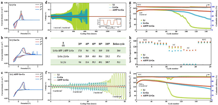
To assess the stability of Li during cycling, we performed a plating/stripping test for Li||Cu batteries. In Li||Cu batteries, the peak current was related to the lithium deposition capacity and electrochemical reaction activity. As shown in Figs. 4a-c, due to the continuous cracking and repairing of the SEI layer, the peak current of Li||Cu cells with bare Li gradually decreases. It implied the gradual decline of Columbic efficiency, in line with Li symmetrical cell tested results. The peak current of Li||Cu cell with Ga-alloy gradually increased and remained stable owing to Li-Ga protection. Similarly, peak current of the AIFP Li-Ga cell protected by composite layer also increased gradually, and peaks in different cycles were well-overlapped, confirming the excellent plating/string of Li on Cu foil. In Li-Ga cell, the lithium insertion for Ga took place between 0.55 V and 0.73 V, while the anodic lithium extraction took place among 0.4, 0.75 and 0.92 V [48]. Furthermore, oxidation peak appeared in Li-Ga coated cell at 1.5–2 V was assigned to electrolyte decomposition. However, AIFP could inhibit the decomposition reaction through the protection of polycarbonate film.
Figure 4
Figure 4.
(a-c) CV scanning of the carbonate electrolytes of different Li metal. (d) Galvanostatic cycling of the symmetric Li||Li, Li-Ga||Li-Ga and Li-Ga AIFP||AIFP Li-Ga symmetric cells at a controlled current density and fixed capacity: 1 mA/cm2, 1 mAh/cm2. (e) EIS evolution of Li symmetrical cell during cycling. (f) Rate performances of electrode symmetric cells at different current densities. Electrochemical performances of the battery with bare Li, Li-Ga and AIFP Li-Ga: (g) Li||LFP; (h) Cycling rate performance; (i) Li||NCM811.
The Li symmetrical cells (electrolyte dosage 20 µL) were assembled to evaluate the lithium cycling behavior under 1 mAh/cm2 (Fig. 4d). The overpotential for bare lithium reaches 100 mV after 225 h, and the voltage suddenly dropped after 380 h due to the formation of Li dendrite. Li-Ga-protected Li anode presented a small overpotential of 68 mV. However, a soft short circuit occurred after 400 h. AIFP Li-Ga cell delivers the lowest overpotential (about 3 mV) and a lifespan of more than 1300 h. When the current was 2 mA/cm2, AIFP Li-Ga symmetric cell also showed low overpotential fluctuation of 10.2 mV after 1640 h. To the contrast, Li-Ga and Li symmetric cells could only cycle for 213 h with high current density (Fig. S12 in Supporting information).
To analyze the interfacial stability, EIS was carried out using symmetric Li cells (Fig. 4e and Fig. S11 in Supporting information). The interfacial impedance of AIFP Li-Ga (26.6 Ω) was comparatively smaller than the bare Li (51.1 Ω) and the Li-Ga protected Li (57.4 Ω) before the cycle due to double SEI layer. With the advance of the lithiation process, the impedance of Li-Ga cells decrease from 13.8 Ω at 60 cycles to 9.1 Ω at 100 cycles, respectively. The Li-Ga dropped to 29.9 Ω for the first 40 cycles and then increasing to 231.2 Ω in the 100th cycle. In the case of bare Li anodes, impedance increased continuously as cycling progresses of 9.6 Ω at 20th cycle to and 269.7 Ω at 100th cycle. Especially, the resistance was 20 times higher than AIFP Li-Ga, which was in consistent with Fig. 4a. Li-Ga protected anode showed a relative stable resistance in the range of 20th to 60th cycle, the resistance began to rise afterward. This indicated that Li-Ga alloy alone cannot inhibit the side-reactions between electrolyte and Li.
Various current densities were used to measure the rate capability of AIFP Li-Ga, Li-Ga, and bare Li symmetric cells (Fig. 4f). Even increasing the current density to 3 mA/cm2 with constant area capacity (1 mAh/cm2), the overpotential of AIFP Li-Ga was stable at all current densities (9 mV at 1 mAh/cm2, 12 mV at 3 mAh/cm2). For bare Li, the overpotential increased from 30 mV at 1 mAh/cm2 to 130 mV at 3 mAh/cm2. Li-Ga protected Li showed similar trend with different current density (from 25 mV at 1 mAh/cm2 to 92 mV at 3 mAh/cm2). When the current was returned to 1 mA/cm2, the average overpotential for AIFP Li-Ga was retained (16 mV), in contrast to that of bare Li (381 mV) and Li-Ga (35 mV).
The stability of Li||LFP full cells (electrolyte usage = 20 µL and cathode loading of 2 mAh/cm2) with bare Li, Li-Ga and AIFP Li-Ga was shown in Fig. 4g. In comparison with the other two anodes, bare Li had the worst cycling stability. After 110 cycles, its capacity was only 26.88 mAh/g, with a capacity decay of 82.08%. The cycling stability of the LiFePO4 full cells was improved on Li-Ga protected Li metal. Nevertheless, after 100 cycles, the capacity began to decline rapidly. Eventually, it reached 80.35 mAh/g after 150 cycles, and there was a 46.43% decay in capacity. However, the cell containing the AIFP Li-Ga was extremely stable, with the capacity of 136.77 mAh/g after 150 cycles, resulting in a capacity decay of only 8.82% (0.09 mAh/g decay per cycle). With cathode loading of 1 mAh/cm2 and electrolyte usage = 20 µL, AIFP Li-Ga still showed capability with the capacity of 126.58 mAh/g after 220 cycles. In comparison, batteries with Li and Li-Ga protected Li were dead after 160 cycles and 180 cycles as a result of the accumulation of dead lithium (Fig. S13 in Supporting information).
The AIFP Li-Ga||LFP full cell offers superior rate performance (Fig. 4h), displaying discharge capacities between 153.3, 144.4, 120.1, 97.1 and 153.4 mAh/g at ampere densities of 0.5, 1, 2, 3 and 0.5 C, respectively. Discharge capacities of the Li-Ga||LFP full cells are 148.2, 136.5, 93.3, 0.8 and 149.4 mAh/g, and the Li||LFP full cell is only 148.4, 139.9, 112.4, 0.9 and 148.5 mAh/g, respectively. Especially, there is a significant difference in capacity at the three types of electrodes (AIFP Li-Ga, Li-Ga and bare Li) at high current densities. Moreover, this AIFP Li-Ga alloy structure exhibits stability even during rapid charge/discharge at high current density, indicating AIFP Li-Ga alloy structure is also beneficial to fast transfer of Li+.
The full cells with LiNi0.6Co0.2Mn0.2O2 (NCM622, loading of 0.8 mAh/cm2, electrolyte usage = 20 µL) and LiNi0.8Co0.1Mn0.1O2 (NCM811, loading of 0.6 mAh/cm2 and electrolyte usage = 20 µL) were prepared. For AIFP Li-Ga||NCM622 cell, an initial capacity of 143.5 mAh/g was obtained at 0.5 C. At the end of 200 cycles, 129 mAh/g and 89.9% capacity retention were obtained, (0.07 mAh/g decay per cycle). Using Li-Ga and bare Li as anodes, the capacity decreased obviously after 120 cycles, and the capacity decreased to 43 mAh/g and 36 mAh/g after 200 cycles (Fig. S14 in Supporting information). Due to the side-reaction between Li and carbonate electrolyte, the liquid electrolyte dries out and dead lithium accumulated. With NCM811 as cathode and AIFP Li-Ga as anode, the initial capacity was 152.6 mAh/g. The capacity was 180 mAh/g after 14 cycles and dropped to 123.7 mAh/g after 200 cycles (0.3 mAh/g dropped per cycle), corresponding to a 68.7% capacity retention (Fig. 4i). Without exception, cell with bare Li decayed quickly after 80 cycles and dead after 100 cycles. With Li-Ga as the anode, the capacity decay was still higher than that of AIFP Li-Ga within 200 cycles, and dropped to 100 mAh/g after 200 cycles (0.43 mAh/g drop per cycle).
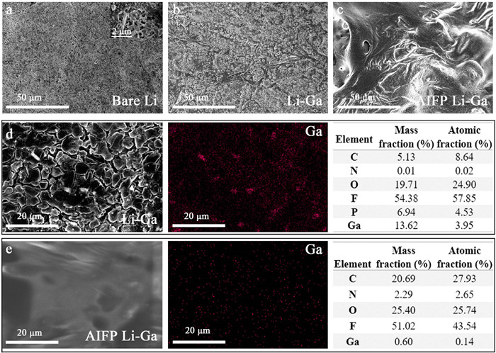
The SEM images after cycling were analyzed, there were lithium dendrites structure on the bare Li metal (Fig. 5a). The surface of Li-Ga protected Li became rough after cycling (Fig. 5b). As expected, the surface of AIFP Li-Ga is uniform without any breakage. The film keeps its original morphology after repeated plating and stripping (Fig. 5c). Even peeling off the polymer film by solvent, the underlying Li-Ga layer keeps smooth (Fig. S15 in Supporting informaation). Furthermore, the composition of Li-Ga protected Li and AIFP Li-Ga were checked by EDS (Figs. 5d and e). For Li-Ga protected Li, the mass ratio of elements F to O was high, suggesting an inorganic compound was formed into large quantities (Fig. 5d). In AIFP Li-Ga, large amount of C and O was detected due to the appearances of organic SEI layer (Fig. 5e). Because of the formation of LiF, high content of F can also be detected. Obviously, composite artificial layer can prevent the Li preferential deposition and result in smooth morphology.
Figure 5
Figure 5.
Bird-view SEM images of Li-stripping electrode. (a) Li. (b) Li-Ga. (c) AIFP Li-Ga. Characterizations of (d) Li-Ga and (e) AIFP Li-Ga with TESM.
In summary, we report a Li2Ga-carbonate polymer interphase layer to solve the volume changes, side reactions and Li dendrite formation of Li metal anode. Carbonate polymer is closely covered on the Li-Ga alloy layer, Li dendrites are effectively suppressed due to the soft carbonate polymer. Li-Ga can fill the small gaps during plating process timely, thus preventing microcracks formation. As a result, Li symmetrical cells with AIFP Li-Ga keep stable at 1 mAh/cm2 for 1300 h (electrolyte usage = 20 µL). When AIFP Li-Ga was coupled with LFP cathode (cathode loading 2 mAh/cm2), reversible capacity delivers 137 mAh/g after 150 cycles. Using NCM622 and NCM811, discharge capacity and capacity of AIFP Li-Ga shows better performance than Li-Ga and bare Li over 200 cycles at 0.5 C rate.
Declaration of competing interest
The authors declare that they have no conflict of interest.
Acknowledgments
This work was supported by Jilin Province Science and Technology Department Major Science and Technology Project (Nos. 20220301004GX, 20220301005GX), Key Subject Construction of Physical Chemistry of Northeast Normal University, National Natural Science Foundation of China (Nos. 21905110, 22102020); National Natural Science Foundation of China (No. 21905041), Special foundation of Jilin Province Industrial technology Research and Development (No. 2019C042), the Fundamental Research Funds for the Central Universities (No. 2412020FZ008).
Supplementary materials
Supplementary material associated with this article can be found, in the online version, at doi:10.1016/j.cclet.2023.108151.
[1]
N. Liu, L. Hu, M.T. McDowell, et al., ACS Nano 5 (2011) 6487–6493. doi: 10.1021/nn2017167
R.D. Deshpande, J.C. Li, Y.T. Cheng, et al., J. Electrochem. Soc. 158 (2011) A845. doi: 10.1149/1.3591094
Figure 1
The mechanism of alloying and in-situ multicomponent SEI formation. (a) Proposed mechanism of SEI formation on Li anode. (b) Bare Li. (c) Ga dispersion on the surface of Li metal. (d) Li-Ga alloy on Li metal. (e) Li-Ga/polymer coated Li metal. (f) The proposed dimethyl carbonate polymerization reactions of EC via the ring-opening reaction. Lithium ethylene dicarbonate (LEDC), polycarbonate diols (PCDL).
Figure 2
(a) X-ray diffraction patterns of different Li metal. (b, c) TEM image of SEI layer. (d) Contact angles of anode. (e, f) 1H and 13C NMR spectra of polymer film on anode. (g-o) XPS of Li anode.
Figure 3
Galvanostatic cycling of the symmetric Li||Li, Li-Ga||Li-Ga and Li-Ga AIFP||AIFP Li-Ga symmetric cells at a controlled current density and fixed capacity from 1st to 10th cycles and the morphology after the cycle: (a) Li||Li, (b) SEM image of Li, (c) AFM image of Li, (d) Li-Ga||Li-Ga, (e) SEM image of Li-Ga, (f) AFM image of Li-Ga, (g) Li-Ga AIFP||AIFP Li-Ga, (h) SEM image of AIFP Li-Ga, (i) AFM image of AIFP Li-Ga.
Figure 4
(a-c) CV scanning of the carbonate electrolytes of different Li metal. (d) Galvanostatic cycling of the symmetric Li||Li, Li-Ga||Li-Ga and Li-Ga AIFP||AIFP Li-Ga symmetric cells at a controlled current density and fixed capacity: 1 mA/cm2, 1 mAh/cm2. (e) EIS evolution of Li symmetrical cell during cycling. (f) Rate performances of electrode symmetric cells at different current densities. Electrochemical performances of the battery with bare Li, Li-Ga and AIFP Li-Ga: (g) Li||LFP; (h) Cycling rate performance; (i) Li||NCM811.
Figure 5
Bird-view SEM images of Li-stripping electrode. (a) Li. (b) Li-Ga. (c) AIFP Li-Ga. Characterizations of (d) Li-Ga and (e) AIFP Li-Ga with TESM.

 DownLoad:

 下载:
下载:


