Figure 1.
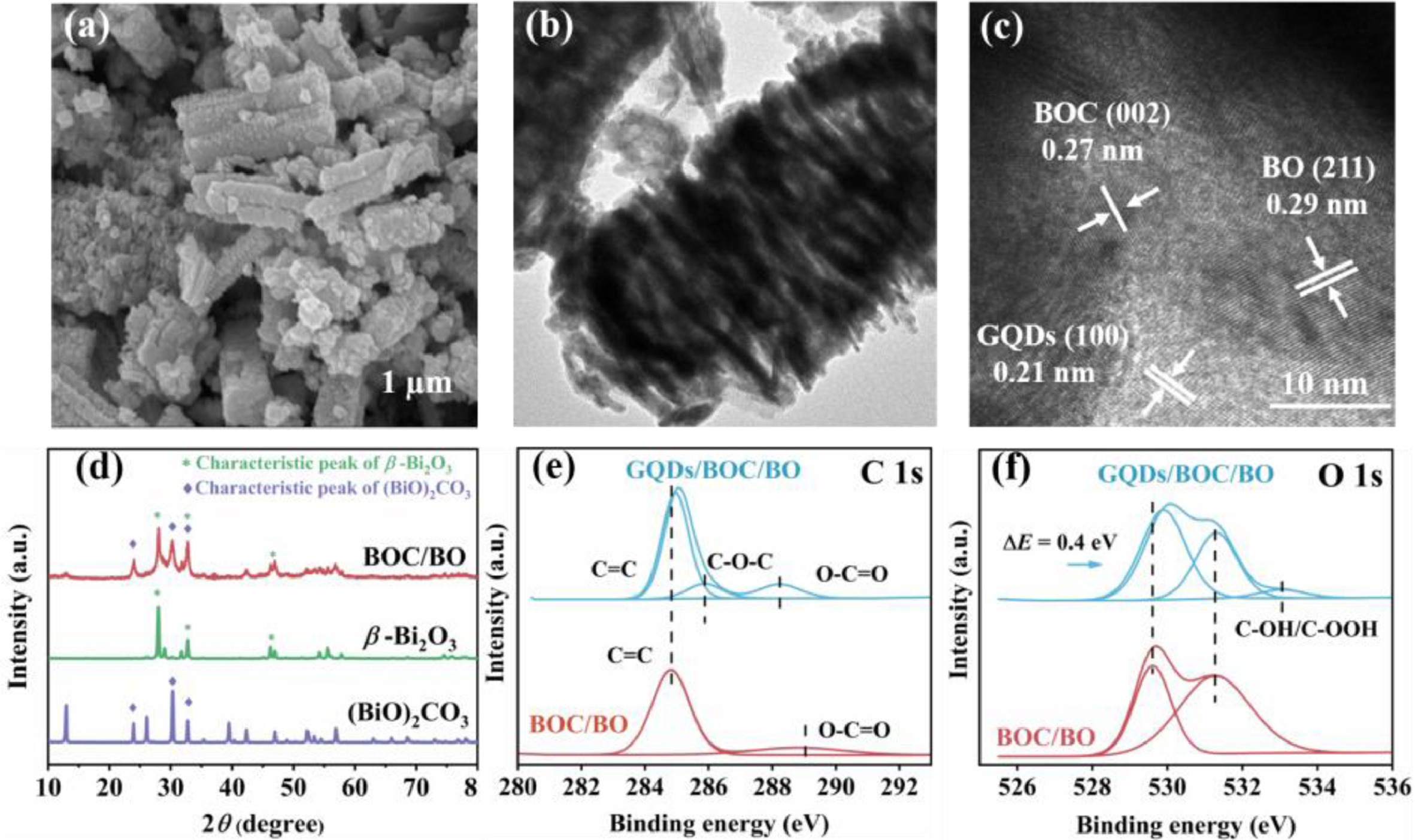
(a) SEM, (b) TEM, and (c) HRTEM images of GQDs/BOC/BO. (d) XRD pattern of the as-prepared BO, BOC, and BOC/BO samples. XPS high resolution (e) C 1s and (f) O 1s spectra of BOC/BO and GQDs/BOC/BO, respectively.
Boosted photocatalytic efficiency of GQDs sensitized (BiO)2CO3/β-Bi2O3 heterojunction via enhanced interfacial charge transfer
Yanxia Wang , Jianping Sheng , Xiaoli Zhao , Ye He , Fan Dong , Yanjuan Sun

Nitrogen oxides (NOx, 95 vol% of NO) emitted from anthropogenic sources, mainly from fossil fuel combustion in automobile exhausts (~55%) and power stations (~45%), have caused severe air pollution, posing a significant threat to human health [1,2]. Therefore, efficient NO removal is critical in air pollution control. However, the conventional disposal strategies, such as absorption, and adsorption, are not applicable for directly removing NO with the sub-ppm level in the atmosphere due to economic limitations.
Semiconductor photocatalysis, a green and efficient technology that directly utilizes solar energy to make NO molecules harmless, has aroused extensive attention in abatement of low concentrations NOx [3-5]. (BiO)2CO3 (BOC), a typical bismuth-based photocatalyst with low toxicity, controllable structure and facile preparation, has recently attracted wide attention in photocatalytic applications, especially in NO purification. However, the bandgap of BOC is too wide (3.1–3.5 eV), which is only ultraviolet light-responsive, seriously limiting its practical application under natural solar light. Besides, more depressingly, the fast recombination of the photo-induced electrons and holes also results in extremely low charge carrier utilization efficiency in BOC. Constructing heterostructure can effectively solve the above limitations by forming a heterogeneous interface, creating the interfacial charge transfer channel, optimizing bandgap and modulating electronic structure [6-8]. Thus, great efforts have been made in BOC-based heterojunction photocatalysts for expanding absorption capacity and promoting directional charge transfer [9-12]. Nevertheless, the further improvement of catalytic efficiency is still restricted by the limited reaction kinetics ascribed to the sluggish interfacial charge transfer dynamics in these traditional BOC-based heterojunctions. Moreover, the inadequate charge transfer will further cause insufficient reactant activation and lead to inevitably toxic by-products accumulation, which finally results in catalyst deactivation [13,14]. For example, toxic by-products (such as NO2) were generally accumulated during the NO photooxidation process when the interfacial charge transfer was blocked, eventually leading to catalyst deactivation. Thus, strengthening the interfacial charge transfer capacity, especially the directional charge transfer, could provide a powerful way to design better photocatalysts. It is highly desirable to construct an advanced bismuth-based heterojunction photocatalyst equipped with highly efficient interfacial charge transfer dynamics.
This work firstly reported a graphene quantum dots (GQDS) sensitized (BiO)2CO3/β-Bi2O3 (BOC/BO) heterojunction for photocatalytic NO purification application. In this system, an efficient interfacial charge transport channel was constructed after hybridizing BOC with β-Bi2O3 (BO) with excellent visible light response [15]. Furthermore, to break the charge transfer dynamics bottleneck, the GQDs with excellent electrical conductivity, were introduced into this heterojunction structure to strengthen the interfacial charge transfer dynamics further. Compared to the single component, the as-synthesized GQDs/BOC/BO composite displayed highly enhanced visible-light NO-photooxidation ability. The interfacial electronic structure and charge transfer behavior were studied through systematically experimental characterization and density functional theory (DFT) calculation. Moreover, the time-dependent NO photooxidation process on different samples was also monitored by in situ diffuse reflectance infrared Fourier transform spectroscopy (DRIFTS) to understand the photocatalytic mechanism in-depth. This work could provide new insights into the mechanism of gas-solid phase photocatalysis and give a fresh idea for constructing advanced heterojunction materials capable of outstanding interfacial charge transfer dynamics.
Fig. 1 and Fig. S1 (Supporting information) display the morphologies and microstructures of these as-prepared samples. As shown in Fig. S1a, the BOC consists of irregular nanoparticles with an average size of 200 nm. BO exhibits a nano rod-like shape with a diameter of 300 nm and length of 1 µm (Fig. S1b). After hybridizing, the BOC/BO sample maintains the initial BOC and BO morphologies (Fig. S1c), and there is also no obvious morphology change after introducing GQDs further (Figs. 1a and b). Fig. 1c exhibits the HRTEM image of the GQDs/BOC/BO composite, and the corresponding lattice fringes of 0.27 and 0.29 nm are consistent with the characteristic spacings of d002 and d211 in BOC and BO, respectively [16,17]. Besides, the detected lattice fringes of 0.21 nm assigned to d100 in GQDs are also consistent with the HRTEM results of pure GQDs presented in Fig. S2 (Supporting information), revealing the successful decoration of the GQDs [18]. XRD analysis was conducted to further characterize the crystal phase of the sample. As shown in Fig. 1d, the sharp peaks indicate the high crystallinity of these samples. The detected three prominent diffraction peaks at 30.30°, 23.89° and 32.72° are assigned to the (161), (121) and (002) planes of orthogonal (BiO)2CO3 (JCPDS No. 84–1752), respectively. And the main peaks at 27.94°, 32.69°, and 46.20° are assigned to (201), (220), and (222) planes of the tetragonal β-Bi2O3 (JCPDS No. 78–1793). After hybridizing, the main characteristic peaks of BOC and BO are all detected in BOC/BO pattern, while there is no diffraction peak of GQDs observed in the GQDs/BOC/BO composite, which could be due to the trace doping amount of GQDs (Fig. S3 in Supporting information) [19].
XPS measurement was further performed to identify the composition and surface chemical state of the prepared samples. The Bi, O, and C elements are well-indexed in the survey scan spectra of BOC/BO and GQDs/BOC/BO (Fig. S4 in Supporting information), and there are no other impurity elements detected, revealing the high purity of these prepared samples. Besides, Figs. 1e and f exhibit the scanning spectra of C and O elements. All the spectra were calibrated by C 1s of aliphatic carbon at 284.8 eV. As shown in the C 1s spectrum of BOC/BO (Fig. 1e), the peaks at 284.8 eV and 289 eV are attributed to the C=C bond and O–C=O bond, respectively [18,20]. And the characteristic peaks of 529.6 and 531.3 eV detected in the O 1s spectrum can be assigned to the lattice oxygen (BO or BOC) and surface chemically adsorbed oxygen species (OH– or CO32–) on the oxide semiconductor [21-24]. When the GQDs were introduced, the new peaks appeared at 286 and 533.1 eV can be observed, which are ascribed to the C–O bond corresponding to the oxygen-related edge functional groups in GQDs (Figs. 1e and f) [20]. The above morphology, phase composition, and microstructures characterization results indicate the successful fabrication of GQDs/BOC/BO composite.
The light absorption capability of these as-prepared catalysts is compared in Fig. 2a. The pure BO shows a strong visible-light absorption up to ~500 nm, while the BOC only ultraviolet response, corresponding to their bandgap energy of 2.23 and 3.41 eV, respectively (Fig. 2b). After hybridizing BOC with BO, the resulted BOC/BO sample displays an enhanced absorption compared to pure BOC and BO, which could be the effect of electronic band structure modulation from the heterointerface formation. To further enhance the light utilization capacity of BOC/BO, GQDs are introduced. As shown in Fig. 2a, benefiting from the excellent intrinsic absorption capacity of GQDs [18], the absorption of GQDs/BOC/BO composite can well cover the ultraviolet-visible-near infrared region and the absorption edge can even reach ~800 nm, which may create more opportunities in visible-light-driven photocatalysis.
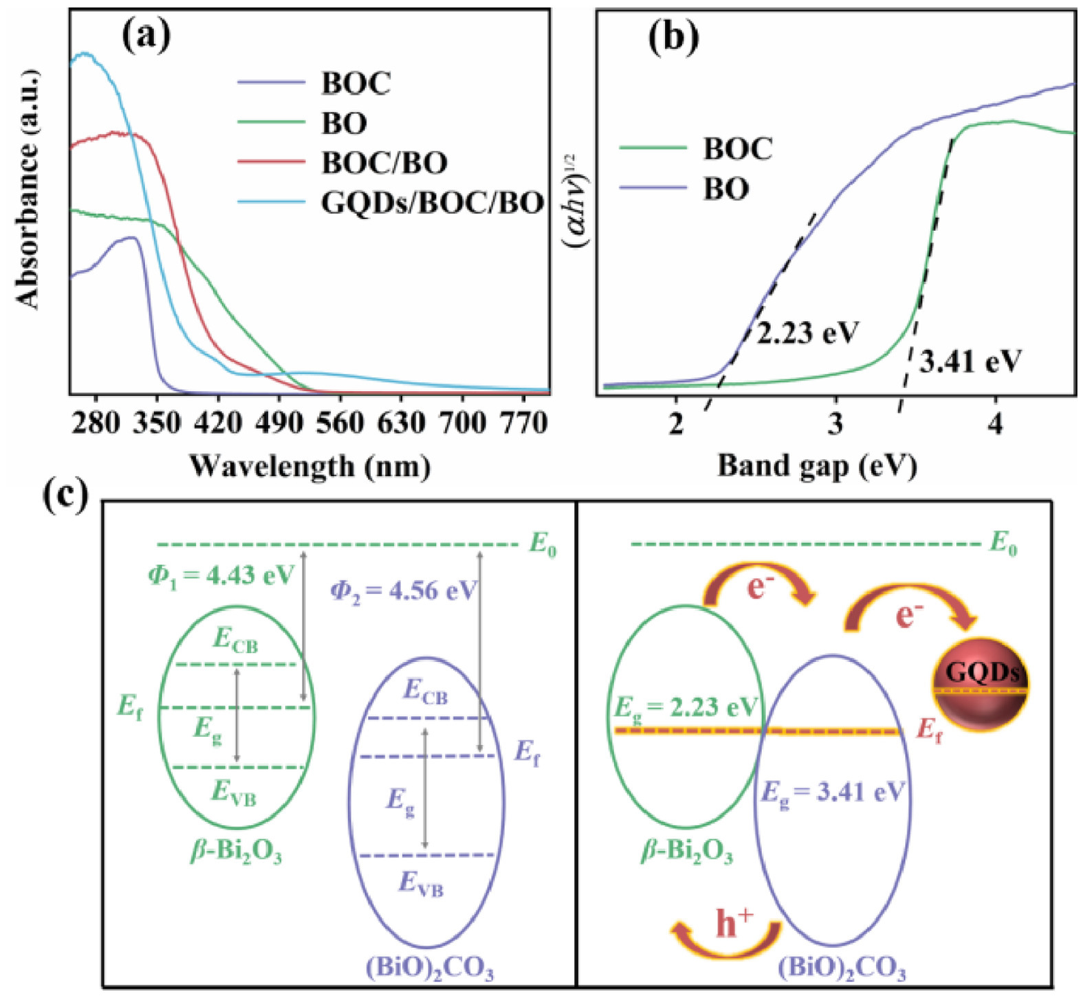
Combined with the DFT results, we revealed that the work function of BO (4.43 eV) is lower than that of BOC (4.56 eV) (Fig. 2c), and the calculated ECB by electronegativity for BO and BOC is 0.61 and 0.33 eV, while the EVB values are 2.84 and 3.74 eV, respectively. The corresponding energy band structures of BO and BOC before contact could be schematically displayed on the left of Fig. 2c. With the BOC/BO heterojunction formed, the Fermi energy levels of both BO and BOC will move to a uniform level after band alignment (right part in Fig. 2c) [25]. Thus, in this as-designed system, when the visible light is irradiated on the photocatalyst surface, the electrons accumulated in the BO conduction band after photoexcitation have higher potential energy than the electrons in the BOC conduction band, which is the driven force for the directed electrons transfer from the conduction band of BO to the conduction band of BOC. Besides, the band energy alignment is favorable to the separation of photo-induced charges, resulting in an extended charge lifetime [26], which may also be attributed to the construction of interface charge transfer channels. Afterward, the GQDs were introduced and further promoted the separation and transfer of photogenerated carriers because GQDs are good electron transport materials, which is consistent with the adsorption results by DFT on GQDs/BOC/BO surface (Table S1 in Supporting information) [27].
DFT calculations were further conducted to evaluate the interaction and charge transfer among BOC and BO interfaces. The optimized configuration of the BOC/BO heterojunction is shown in Fig. 3a, and the corresponding image of the Electron location function (ELF, shown in Fig. 3b) manifests the strong covalent interaction between O atoms of BOC and Bi atoms of BO, which means an interfacial channel has been created for high-speed electron transportation. Simultaneously, the charge difference distribution in Fig. S5a (Supporting information) further points out the direction and intensity of electron transfer between the BOC and BO interface. It can be observed that the charge of the Bi atom of BO can efficiently transfer to the O atom of BOC through this interfacial channel. Besides, the Bader charge was calculated based on the reasonable and optimized geometric structure of the BOC/BO heterostructure. And the Bader charge data shows that the number of electrons in the BO (222.12 e) is reduced compared to the initial structure (224 e), indicating the path of charge transfer would be from BO to BOC again.
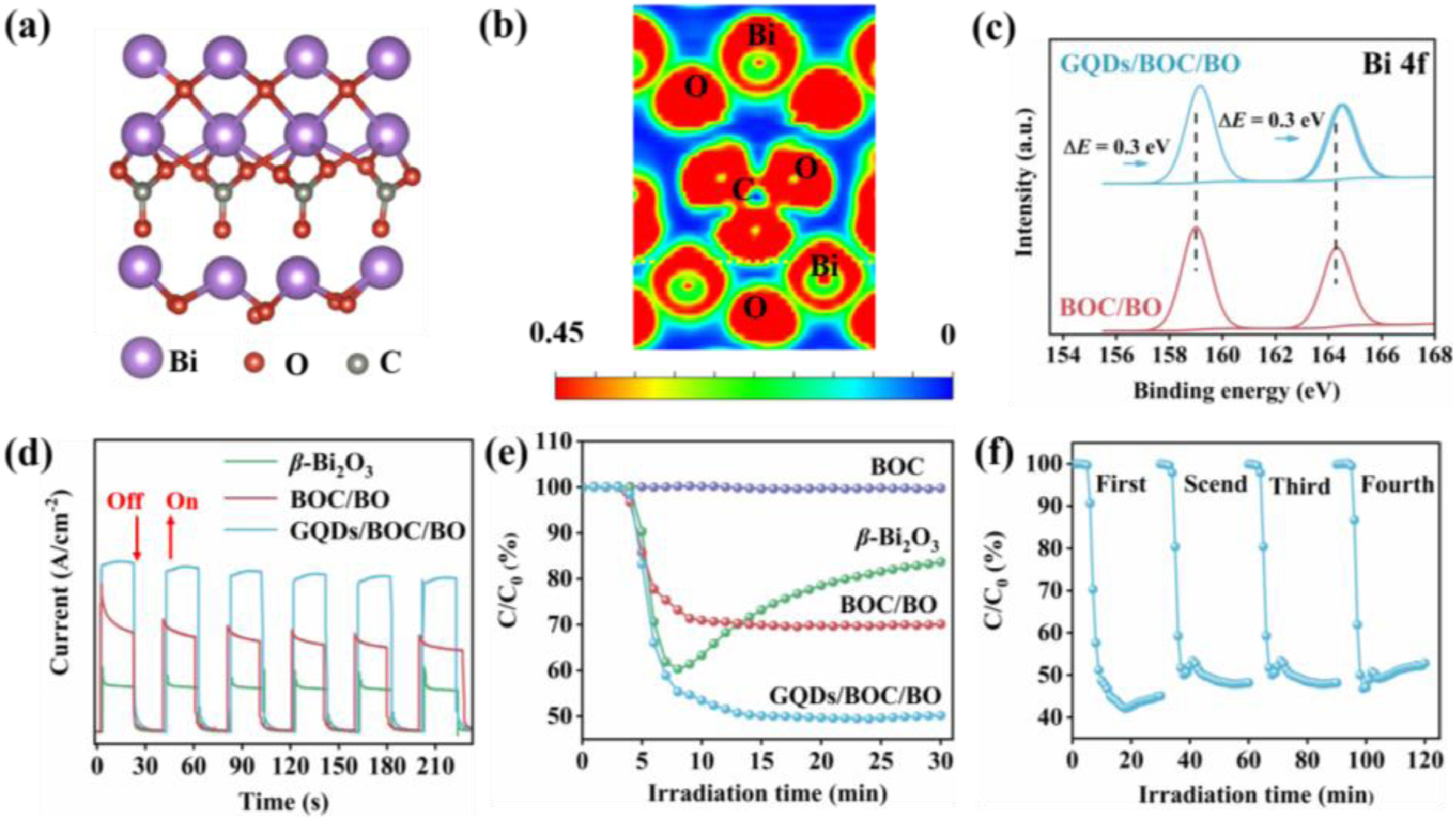
In addition, the effect of exogenetic GQDs on charge transport in BOC/BO heterojunctions was further investigated. The calculated DFT results indicate that the charges in the BOC/BO heterojunction will be further transferred and accumulated to the GQDs sites (Fig. S5b in Supporting information). XPS was also performed to verify the above theoretical results. As shown in Fig. 3c, the binding energy of Bi 4f in the GQDs/BOC/BO composite has a 0.3 eV positive shift toward the higher energy in comparison with the BOC/BO one, indicating an effective interaction between the exogenetic GQDs and BOC/BO heterostructure and also uncovers the electron delivery from BOC/BO to GQDs [28,29].
To sum up, we theoretically and experimentally demonstrate that there is an effective interaction between the BOC/BO heterointerface, which is beneficial for high-speed electron transportation. Meanwhile, the interfacial charge transfer of BOC/BO is further enhanced due to the introduction of GQDs, and we speculate that the transmission route of photogenerated electrons would be from BO to BOC, and finally accumulated on GQDs sites to participate in the following photocatalytic reactions. Moreover, as displayed in Fig. 3d, the apparent transient photocurrent response results show that GQDs/BOC/BO has the best photoelectric conversion capacity, followed by BOC/BO, and the worst is pure BO. This regularity of the photocurrent signal is also consistent with the previous discussion.
The photocatalytic NO removal was evaluated under visible light irradiation. As shown in Fig. 3e, the pure BOC is inactive due to its wide band gap and poor visible light responsibility. For pure BO, the NO degradation rate can reach up to 40% in the first 10 min, but rapid deactivation is inevitable. This decay may be attributed to the accumulation of toxic by-products on the BO surface, which impedes the continuous reaction. The BOC/BO heterostructure and GQDs/BOC/BO composite exhibit the enhanced photocatalytic degradation ability toward NO. Especially, the NO removal rate is 51% on GQDs/BOC/BO composite because of its excellent charge separation and directed delivery ability. The stability of the GQDs/BOC/BO composite was also evaluated by performing four photocatalytic tests (Fig. 3f). No obvious deactivation is observed after four cycling tests, indicating superior photocatalytic stability on the as-prepared GQDs/BOC/BO composite.
In summary, the highly enhanced photocatalytic activity and stability of NO degradation on the BOC/BO heterojunction can be ascribed to the elevated charge separation and transportation through the as-designed interfacial channel. Besides, Compared with BOC/BO, GQDS/BOC/BO has better activity and stability, which is attributed to the enhancement of the interfacial charge transfer dynamics by GQDs, and inducing more active species to further convert toxic byproducts.
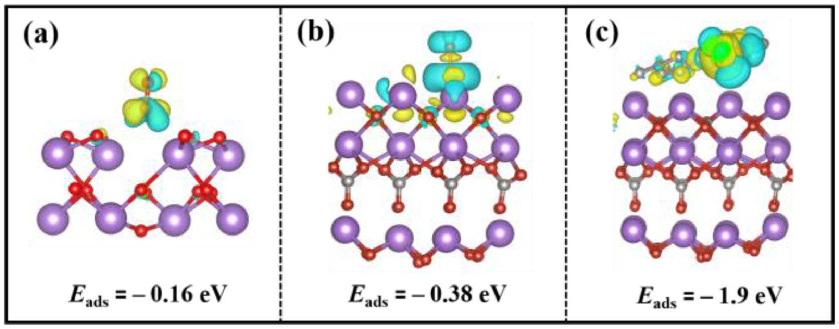
Reactant adsorption on the catalyst surface is significant in heterogeneous catalysis because it is related to the subsequent catalytic reaction. We investigated the adsorption and activation of NO molecules by DFT calculations (Fig. 4). The adsorption energies of NO on BO, BOC/BO, and GQDs/BOC/BO composite were −0.16 eV, −0.38 eV, and −1.9 eV, respectively, indicating that the BOC/BO heterostructure and GQDs/BOC/BO composite promote the adsorption of NO molecules. In addition, the charge difference density and Bader charge were evaluated between the NO and substrates. It reveals that the BOC/BO heterostructure and GQDs/BOC/BO composite facilitated the charge transfer from the photocatalyst to NO molecules with the enlarged N–O bond (Table S1 in Supporting information). Overall, the construction of heterostructure not only has a good adsorption effect on NO molecules but also can stretch the N–O bond to the greatest extent, inducing an excellent activation effect on NO molecules. What's more, the smaller Gibbs free energy (G) value (Fig. S6 in Supporting information) proves that constructing heterostructure can more easily promote the adsorption of NO molecules on thermodynamics. The above results indicate that the composite structure exhibits a better activation effect on NO molecules compared with pure phases, which is attributed to the construction of interfacial channels and the strengthening of the charge transfer process after the introduction of GQDs with an excellent charge transport effect.
Correspondingly, in order to simplify the problem and further reveal the essential reasons for the stabilizing activity of GQDs/BOC/BO, DRIFTS was used to in situ monitor the evaluation of intermediates on the surface of BO and GQDs/BOC/BO in real-time. Table 1 summarizes all the assignments of the observed IR bands. As shown in Fig. 5a, the plentiful adsorption peaks including N2O4 (820 cm−1, 907 cm−1) [30,31], NO2− (868 cm−1, 998 cm−1 and 1200cm−1) [32], NO3− (925 cm−1, 1063 cm−1) [33], NO (1038 cm−1), NOH (1105 cm−1, 1157 cm−1) [34], N2O22− (1321 cm−1) and N2O3 (1340 cm−1) [35,36] appeared on the pure BO during the adsorption process. In contrast, on the surface of GQDs/BOC/BO composite (Fig. 5b), fewer absorption peaks about NO3− (1063 cm−1, 1097 cm−1), NO−/NOH (1157 cm−1), N2O22− (1321 cm−1), N2O3 (1340 cm−1) emerged once the NO was introduced [37]. In particular, the characteristic peaks of N2O4 (820 cm−1, 907 cm−1) on the surface cannot be detected compared with BO, indicating less accumulation of toxic by-products. Another point worth noting is that the peak located at 844 cm−1 about nitrite accumulated significantly. In order to reveal this phenomenon, we calculated the adsorption of NO2 molecules on catalyst surfaces as shown in Fig. S7 (Supporting information). The results of DFT show that NO2 molecules adsorbed on the GQDS/BOC/BO surface obtained more electrons than on the BO surface (Table S2 in Supporting information). The above results show that adequate charge transfer could accelerate intermediates by-products to get electrons to form NO2− (844 cm−1) [38], and more nitrite is attributed to efficient charge transfer through interfacial charge transfer channels and the excellent activation ability of heterostructure. To sum up, more photogenerated carriers are helpful for the photocatalytic NO oxidation to nitrate, which is attributed to heterostructure with interfacial channel that strengthens the charge transfer dynamics.
 DownLoad:
CSV
DownLoad:
CSV

|
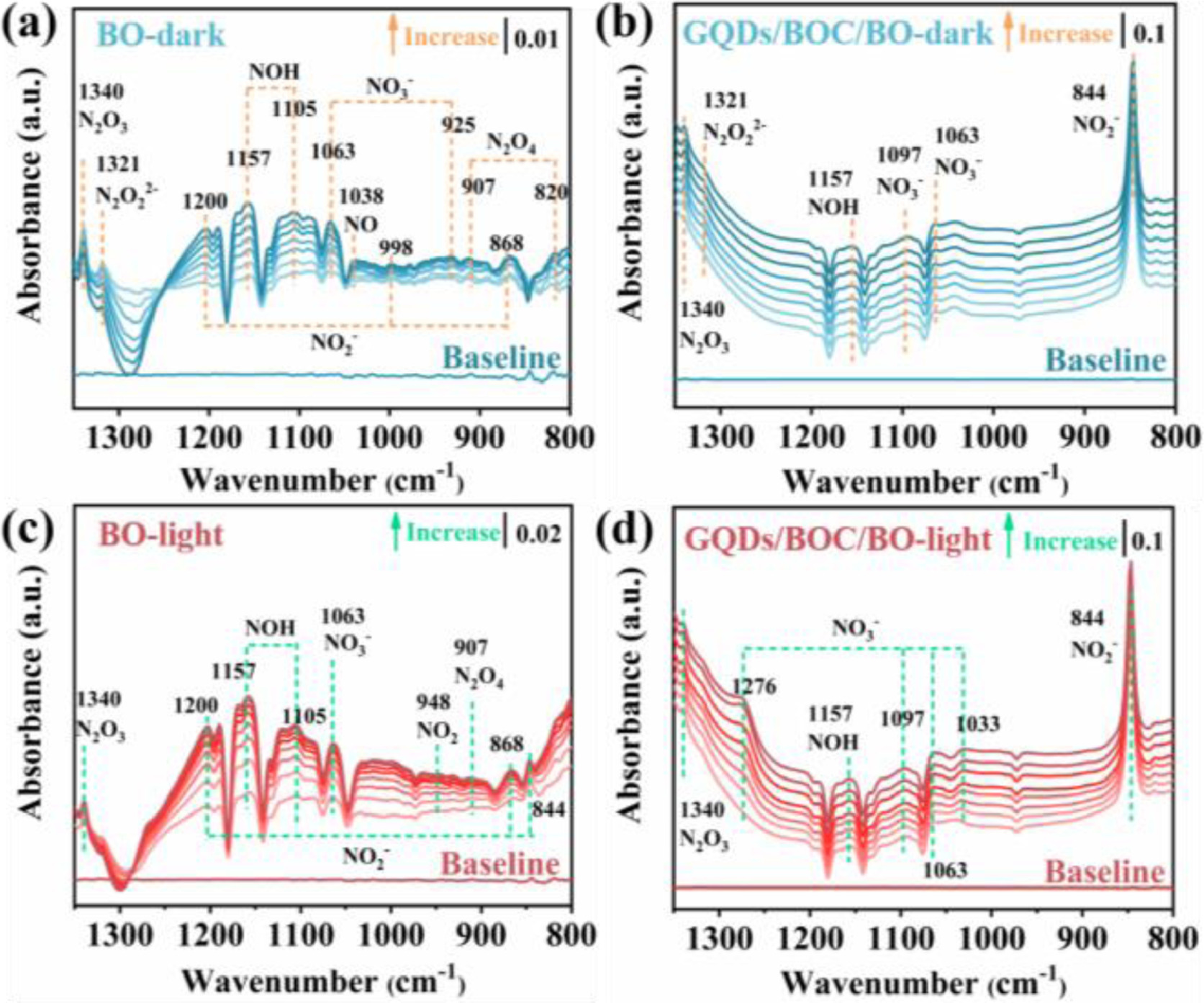
The time-dependent IR spectra of photocatalysts under visible-light irradiation were recorded once the adsorption equilibrium was achieved. Related reports have confirmed that catalysts with strong carrier transferability can promote surface charge enrichment. Then adsorbed oxygen could get electrons to generate radicals that can activate the intermediates. In pure BO, compared with the adsorption state under dark conditions, no peaks change significantly but the intensity of the peaks was enhanced (Fig. 5c), reflecting that light promotes the adsorption process and BO has a weak ability to further convert NOx into nitrite or nitrate. Moreover, the DFT results about NO molecules absorption show that NO molecules donated electrons to BO during the adsorption process, indicating BO cannot provide more charges to participate in the reaction (Table S1). The above results indicate that BO cannot provide more photogenerated charges and generate more active species, resulting in the accumulation of many toxic by-products on the surface and inactivation. However, in GQDs/BOC/BO composite, new peaks of NO3− (1033 cm−1, 1276 cm−1) appeared compared to dark conditions, along with the further growth of NO2− (844 cm−1) (Fig. 5d) [39]. And nitrite can be further activated by free radicals, meaning GQDs/BOC/BO composite could generate more nitrites or nitrates than pure BO without toxic-product (NO2/ N2O4). Finally, this can be summarized as the construction of interfacial charge transfer channels is beneficial to adequate charge transfer in the heterostructure, promoting pollutant activation and further improving photocatalytic activity.
To sum up, BOC/BO heterostructure has been synthesized via a one-step hydrothermal method, which achieves high efficiency and stable visible-light NO-photooxidation ability. This study combines experimental and theoretical methods to verify that an efficient interfacial charge transport channel was constructed in the heterogeneous structure, which can enable better transfer of photogenerated carriers than pure phase materials. Furthermore, the introduction of GQDs with excellent electrical conductivity is beneficial to strengthening the interfacial charge transfer dynamics and thus enhancing the photocatalytic activity. Combined with the results of in situ DRIFTS, it is revealed that the photocatalytic performance of BO catalyst originates from photogenerated carriers and active free radicals. The catalyst deactivation is attributed to toxic by-products remaining on the surface of BO. The interfacial charge transport could facilitate the conversion of toxic byproducts and drive the subsequent photocatalytic reaction to make the catalyst stable in NO removal. These findings can provide new insights into the impact of heterojunction interface structure on photocatalytic reactions.
The authors declare no competing financial interest.
This work was supported by the National Natural Science Foundation of China (Nos. 22172019, 52002054) and the Sichuan Science and Technology Program (No. 2022JDRC0084).
Supplementary material associated with this article can be found, in the online version, at doi:
H.Z. Streicher, P.A. Gabow, A.H. Moss, et al., Ann. Intern. Med. 94 (1981) 758–762. doi: 10.7326/0003-4819-94-6-758
L. Xiao, P. Chen, W.P. Yang, et al., Catal. Sci. Technol. 11 (2021) 7807–7839. doi: 10.1039/D1CY01776D
R.B. Wei, Z.L. Huang, G.H. Gu, et al., Appl. Catal. B: Environ. 231 (2018) 101–107. doi: 10.1016/j.apcatb.2018.03.014
Y.F. Zhao, B. Zhao, J.J. Liu, et al., Angew. Chem. Int. Ed. 55 (2016) 4215–4219. doi: 10.1002/anie.201511334
P.Y. Kuang, J.R. Ran, Z.Q. Liu, et al., Chem. Eur. J. 21 (2015) 15360–15368. doi: 10.1002/chem.201501183
P. Zhang, T. Wang, X. Chang, et al., Acc. Chem. Res. 49 (2016) 911–921. doi: 10.1021/acs.accounts.6b00036
Y.J. Ren, D.Q. Zeng, W.J. Ong, Chin. J. Catal. 40 (2019) 289–319. doi: 10.1016/S1872-2067(19)63293-6
Y. Ma, X. Wang, Y. Jia, et al., Chem. Rev. 114 (2014) 9987–10043. doi: 10.1021/cr500008u
S. Bai, W.Y. Jiang, Z.Q. Li, et al., ChemNanoMat 1 (2015) 223–239. doi: 10.1002/cnma.201500069
P.V. Kamat, J. Phys. Chem. Lett. 3 (2012) 663–672. doi: 10.1021/jz201629p
B.H. Jing, Z.M. Ao, W.N. Zhao, et al., J. Mater. Chem. A 8 (2020) 20363–20372. doi: 10.1039/D0TA06060G
J. Zhou, D. Li, W. Zhao, et al., ACS. Appl. Mater. Inter. 13 (2021) 23843–23852. doi: 10.1021/acsami.1c05617
R. Long, K.K. Mao, X.D. Ye, et al., J. Am. Chem. Soc. 135 (2013) 3200–3207. doi: 10.1021/ja311739v
G. Kresse, J. Furthmuller, Phys. Rev. B 54 (1996) 11169–11186. doi: 10.1103/PhysRevB.54.11169
R.P. Hu, X. Xiao, S.H. Tu, et al., Appl. Catal. B: Environ. 163 (2015) 510–519. doi: 10.1016/j.apcatb.2014.08.025
H. Liu, M. Luo, J.C. Hu, et al., Appl. Catal. B: Environ. 140-141 (2013) 141–150.
X. Zu, Y. Zhao, X. Li, et al., Angew. Chem. Int. Ed. 60 (2021) 13840–13846. doi: 10.1002/anie.202101894
X. Zhao, B. Deng, F. Li, et al., J. Hazard. Mater. 420 (2021) 126577. doi: 10.1016/j.jhazmat.2021.126577
J. Di, J. Xia, M. Ji, et al., ACS. Appl. Mater. Interfaces 7 (2015) 20111–20123. doi: 10.1021/acsami.5b05268
S. Kadian, G. Manik, Food. Chem. 317 (2020) 126457. doi: 10.1016/j.foodchem.2020.126457
D. Barreca, F. Morazzoni, G.A. Rizzi, et al., Phys. Chem. Chem. Phys. 3 (2001) 1743–1749. doi: 10.1039/b009482j
B. Lei, W. Cui, J.P. Sheng, et al., Sci. Bull. 65 (2020) 467–476. doi: 10.1016/j.scib.2020.01.007
G. Rajender, J. Kumar, P.K. Giri, Appl. Catal. B: Environ. 224 (2018) 960–972. doi: 10.1016/j.apcatb.2017.11.042
N.T.N. Anh, R.A. Doong, ACS. Appl. Nano Mater. 1 (2018) 2153–2163.
H. Wang, W. Cui, X.A. Dong, et al., Chem. Eng. J. 390 (2020) 124609. doi: 10.1016/j.cej.2020.124609
H. Wu, H.L. Tan, C.Y. Toe, et al., Adv. Mater. 32 (2020) 1904717. doi: 10.1002/adma.201904717
D.L. Shen, W.F. Zhang, F.Y. Xie, et al., J. Power. Sources 402 (2018) 320–326. doi: 10.1016/j.jpowsour.2018.09.056
J. Di, J.X. Xia, M.F. Chisholm, et al., Adv. Mater. 31 (2019) 1807576. doi: 10.1002/adma.201807576
G.H. Qiu, T. Wang, X.L. Li, et al., Ind. Eng. Chem. Res. 59 (2020) 11517–11526. doi: 10.1021/acs.iecr.0c01796
P. Chen, H. Wang, H.J. Liu, et al., Appl. Catal. B: Environ. 242 (2019) 19–30. doi: 10.1016/j.apcatb.2018.09.078
B. Azambre, L. Zenboury, A. Koch, et al., J. Phys. Chem. C 113 (2009) 13287–13299.
M. Kantcheva, A.S. Vakkasoglu, J. Catal. 223 (2004) 364–371. doi: 10.1016/j.jcat.2004.02.006
P. Chen, Y.J. Sun, H.J. Liu, et al., Nanoscale 11 (2019) 2366–2373. doi: 10.1039/C8NR09147A
M. Kantcheva, J. Catal. 204 (2001) 479–494. doi: 10.1006/jcat.2001.3413
K.I. Hadjiivanov, Catal. Rev. 42 (2000) 71–144. doi: 10.1081/CR-100100260
S. Chen, H.Q. Wang, M.P. Shi, et al., Environ. Sci. Technol. 52 (2018) 8568–8577. doi: 10.1021/acs.est.8b00655
J.C.S. Wu, Y.T. Cheng, J. Catal. 237 (2006) 393–404. doi: 10.1016/j.jcat.2005.11.023
H. Wang, Y.J. Sun, G.M. Jiang, et al., Environ. Sci. Technol. 52 (2018) 1479–1487. doi: 10.1021/acs.est.7b05457
H. Li, J. Shang, Z.P. Yang, et al., Environ. Sci. Technol. 51 (2017) 5685–5694. doi: 10.1021/acs.est.7b00040

Figure 1 (a) SEM, (b) TEM, and (c) HRTEM images of GQDs/BOC/BO. (d) XRD pattern of the as-prepared BO, BOC, and BOC/BO samples. XPS high resolution (e) C 1s and (f) O 1s spectra of BOC/BO and GQDs/BOC/BO, respectively.

Figure 2 (a) UV-vis DRS of as-prepared samples. (b) The plot of (αhv)2 vs. photon energy of BOC and BO based on UV-vis DRS spectra. (c) The heterostructure diagram of BOC/BO before (left) and after (right) the formation of heterojunction. Eg and Ef are the bandgap and the Fermi level of Semiconductor material.

Figure 3 (a) The side view of the modeled interface structure of BOC/BO; (b) the DFT calculated electron location function of BOC/BO heterostructure; (c) XPS high resolution Bi 4f spectra of BOC/BO and GQDs/BOC/BO; (d) transient photocurrent responses, (e) the visible-light photocatalytic activity of the as-prepared samples, and (f) recycling tests of GQDs/BOC/BO.

Figure 4 Charge density difference of NO adsorption and activation at (a) BO, (b) BOC/BO, and (c) GQDs/BOC/BO surface. Electron accumulation is in blue and depletion in yellow. The purple, red, and gray spheres represent Bi, O, and C atoms, respectively.

Figure 5 In situ DRIFTS spectra monitoring the dynamic evolution of NO (a, b) adsorption and (c, d) oxidation under visible light irradiation on BO and GQDs/BOC/BO samples.
Table 1. Assignments of the IR bands observed during photocatalytic NO oxidation processes over BO and GQDs/BOC/BO under visible light irradiation.
|
|
 下载: 导出CSV

 扫一扫看文章

扫一扫关注我们